EP0196963A1 - Wavelength multiplexer-demultiplexer corrected for geometric and chromatic aberrations - Google Patents
Wavelength multiplexer-demultiplexer corrected for geometric and chromatic aberrations Download PDFInfo
- Publication number
- EP0196963A1 EP0196963A1 EP86400573A EP86400573A EP0196963A1 EP 0196963 A1 EP0196963 A1 EP 0196963A1 EP 86400573 A EP86400573 A EP 86400573A EP 86400573 A EP86400573 A EP 86400573A EP 0196963 A1 EP0196963 A1 EP 0196963A1
- Authority
- EP
- European Patent Office
- Prior art keywords
- mirror
- spherical
- contact
- face
- index
- Prior art date
- Legal status (The legal status is an assumption and is not a legal conclusion. Google has not performed a legal analysis and makes no representation as to the accuracy of the status listed.)
- Granted
Links
Images
Classifications
-
- G—PHYSICS
- G02—OPTICS
- G02B—OPTICAL ELEMENTS, SYSTEMS OR APPARATUS
- G02B6/00—Light guides; Structural details of arrangements comprising light guides and other optical elements, e.g. couplings
- G02B6/24—Coupling light guides
- G02B6/26—Optical coupling means
- G02B6/28—Optical coupling means having data bus means, i.e. plural waveguides interconnected and providing an inherently bidirectional system by mixing and splitting signals
- G02B6/293—Optical coupling means having data bus means, i.e. plural waveguides interconnected and providing an inherently bidirectional system by mixing and splitting signals with wavelength selective means
- G02B6/29304—Optical coupling means having data bus means, i.e. plural waveguides interconnected and providing an inherently bidirectional system by mixing and splitting signals with wavelength selective means operating by diffraction, e.g. grating
- G02B6/29305—Optical coupling means having data bus means, i.e. plural waveguides interconnected and providing an inherently bidirectional system by mixing and splitting signals with wavelength selective means operating by diffraction, e.g. grating as bulk element, i.e. free space arrangement external to a light guide
- G02B6/29307—Optical coupling means having data bus means, i.e. plural waveguides interconnected and providing an inherently bidirectional system by mixing and splitting signals with wavelength selective means operating by diffraction, e.g. grating as bulk element, i.e. free space arrangement external to a light guide components assembled in or forming a solid transparent unitary block, e.g. for facilitating component alignment
-
- G—PHYSICS
- G02—OPTICS
- G02B—OPTICAL ELEMENTS, SYSTEMS OR APPARATUS
- G02B6/00—Light guides; Structural details of arrangements comprising light guides and other optical elements, e.g. couplings
- G02B6/24—Coupling light guides
- G02B6/26—Optical coupling means
- G02B6/28—Optical coupling means having data bus means, i.e. plural waveguides interconnected and providing an inherently bidirectional system by mixing and splitting signals
- G02B6/293—Optical coupling means having data bus means, i.e. plural waveguides interconnected and providing an inherently bidirectional system by mixing and splitting signals with wavelength selective means
- G02B6/29304—Optical coupling means having data bus means, i.e. plural waveguides interconnected and providing an inherently bidirectional system by mixing and splitting signals with wavelength selective means operating by diffraction, e.g. grating
- G02B6/29305—Optical coupling means having data bus means, i.e. plural waveguides interconnected and providing an inherently bidirectional system by mixing and splitting signals with wavelength selective means operating by diffraction, e.g. grating as bulk element, i.e. free space arrangement external to a light guide
- G02B6/2931—Diffractive element operating in reflection
-
- G—PHYSICS
- G02—OPTICS
- G02B—OPTICAL ELEMENTS, SYSTEMS OR APPARATUS
- G02B6/00—Light guides; Structural details of arrangements comprising light guides and other optical elements, e.g. couplings
- G02B6/24—Coupling light guides
- G02B6/26—Optical coupling means
- G02B6/28—Optical coupling means having data bus means, i.e. plural waveguides interconnected and providing an inherently bidirectional system by mixing and splitting signals
- G02B6/293—Optical coupling means having data bus means, i.e. plural waveguides interconnected and providing an inherently bidirectional system by mixing and splitting signals with wavelength selective means
- G02B6/29346—Optical coupling means having data bus means, i.e. plural waveguides interconnected and providing an inherently bidirectional system by mixing and splitting signals with wavelength selective means operating by wave or beam interference
- G02B6/29361—Interference filters, e.g. multilayer coatings, thin film filters, dichroic splitters or mirrors based on multilayers, WDM filters
-
- G—PHYSICS
- G02—OPTICS
- G02B—OPTICAL ELEMENTS, SYSTEMS OR APPARATUS
- G02B6/00—Light guides; Structural details of arrangements comprising light guides and other optical elements, e.g. couplings
- G02B6/24—Coupling light guides
- G02B6/26—Optical coupling means
- G02B6/28—Optical coupling means having data bus means, i.e. plural waveguides interconnected and providing an inherently bidirectional system by mixing and splitting signals
- G02B6/293—Optical coupling means having data bus means, i.e. plural waveguides interconnected and providing an inherently bidirectional system by mixing and splitting signals with wavelength selective means
- G02B6/29379—Optical coupling means having data bus means, i.e. plural waveguides interconnected and providing an inherently bidirectional system by mixing and splitting signals with wavelength selective means characterised by the function or use of the complete device
- G02B6/2938—Optical coupling means having data bus means, i.e. plural waveguides interconnected and providing an inherently bidirectional system by mixing and splitting signals with wavelength selective means characterised by the function or use of the complete device for multiplexing or demultiplexing, i.e. combining or separating wavelengths, e.g. 1xN, NxM
Definitions
- the present invention relates to a wavelength multiplexer-demultiplexer with wavelength separator and concave mirror, more particularly intended to constitute a component for teletransmission installations by optical fibers.
- the latter in an operation as a demultiplexer for example, transforms the beam of mixed lights received from the input fiber in a parallel beam towards a plane diffraction grating, and in return focuses on the ends of the output fibers, the different parallel monochromatic beams diffracted by the grating.
- Such devices whether arrays or dielectric mirrors, give better results with a parabolic rather than spherical concave mirror. Indeed the spherical aberrations of a spherical mirror do not allow to reach the same degree of quality of stigmatism as with a parabolic mirror.
- the French patent published under No. 2,543,768 provides a first improvement, applied to a network device, by the constitution of a plane diopter separating two optical media of different indices between the concave mirror and the network, thus making it possible the use of a simple spherical mirror.
- the spherical aberrations of the mirror can in fact then be corrected by a suitable choice of the indices of the two circles of the diopter.
- the present invention which applies in the same way to one or the other type of component, therefore allows both. the correction of spherical aberrations of a spherical concave mirror of easy industrial production, and the correction of chromatic aberrations due to the presence of a diopter.
- the invention therefore relates to a multiplexer-demultiplexer of the type in which the lights of different wavelengths to be mixed or separated are carried by optical transmission fibers whose ends are arranged in the vicinity immediate swimming of the apparent focus of a concave mirror associated with a wavelength separation system.
- Element 1 is a simple support for the input and output optical fibers.
- Element 2 is just the network support.
- Element 3 is an intermediate element and element 4 only includes the concave mirror.
- the fiber-holder element./ will advantageously be able to be produced using the method described by the French patent published under No. 2,411,424 and relating to a fiber optic connector; it will suffice to make only one of the two blocks which would be necessary for a connector.
- the patent published under No. 2,543,768 recalls in more detail a preferential way of mounting the fibers in the block 1 and of making their ends flush with the joint plane 12.
- the network-carrying element 2 is a transparent block of which one side is polished to form the parting line 12 with the element 1 and the other side of which carries a planar diffraction grating 15.
- the grating 15 is produced in the usual way, that is to say by copying an original etched or holographic network, then covering with a reflective metallic layer. To allow passage without deflection of the light coming from or coming from the fibers 9, it is -necessary to locally neutralize the network 15 in the area 16 where it crosses the fiber opening cone, that is to say the angular zone of acceptance of the light rays in the core of the fibers. To neutralize the network in this zone 16, we will proceed by photolithography to make the reflective layer disappear locally. It will be observed that this does not cause any alteration of the network outside the zone treated and in particular at the limit of this zone.
- the surface carrying the network is glued to the intermediate element 3 of the same index as the element 2, it will suffice to use as a glue a resin of the same index as that of the resin forming the support of the network 15 the latter itself being chosen to present an index as close as possible to that of the two blocks 2 and 3.
- a glue a resin of the same index as that of the resin forming the support of the network 15 the latter itself being chosen to present an index as close as possible to that of the two blocks 2 and 3.
- the intermediate element 3 has a polished flat face . for bonding to the network 15 of the element 2 and a spherical face 34 to form the joint surface with the element 4.
- the face opposite to the spherical joint surface 34 is itself a spherical surface treated to form a concave mirror 8.
- the element 7 is made of material of index n ′ different from the index n of the elements 2 and 3.
- n is less than n 'and the concavity of the surface 34 is opposite to that of the mirror 8. If the choice of the indices n and n' led to taking n less than n 'the concavity of the surface 34 should then be in the same direction as that of the mirror 8.
- the optical operation of the assembly thus produced is entirely identical to that of the assembly described in patent 2,496,260.
- the mixed light is brought in by the 'one of the fibers 9 whose end is at the apparent focus of the mirror 8, that is to say at the location of the image of its real focus in the diopter 34.
- the rays from from the end of the fiber are therefore returned by the mirror 8 in a parallel beam to the network 15 which disperses it in as many parallel beams as wavelengths in mixed light.
- each parallel beam is focused on the end of an output fiber 9.
- substantially equal chromatic dispersion areas have been chosen, making it possible not to introduce chromatic aberrations.
- the curvature of the spherical diopter 34 is then chosen as a function of the indices n and n 'of the materials so as to also compensate for the spherical aberration of the mirror.
- FIG. 3 shows an alternative embodiment facilitating the adjustment of the device.
- the element. intermediate 3 is in two parts 31 and 32, both for example of a material of the same index n only element 2, and separated by a joint plane 35.
- the adjustment of alignment of the fibers can only be carried out before final bonding by sliding the plane of the door unit -fibers 1 on the joint plane 12.
- the assembly 32-4 can also be adjusted before bonding relative to the block 31 and to the rest of the component by sliding on the joint plane 35.
- the longitudinal displacement is reduced to + 8 microns for a focal length of 72.137 mm.
Abstract
Multiplexeur-démultiplexeur comprenant: a) un élément porte-fibres (1) dans lequel sont noyées les fibres d'entrée et de sortie (9) avec leurs extremités affleurant sur une surface plane de contact (12) avec l'élément suivant, b) un élément (2) portant le système de séparation de loggueurs d'ondes (15), avec une surface plane de contact avec l'élément porte-fibres et une face plane opposée de contact avec l'élément suivant, c) un élément intermédiaire (3) de même indice n que l'élément portant le système de séparation de longueurs d'ondes) avec une face plane de contact (23) avec l'élément portant le système de séparation de longueurs d'ondes, et une face sphérique de contact (34) avec l'élément suivant, d) un élément miroir (4) avec une face sphérique de contact avec l'élément intermédiaire et une face sphérique opposée traitée pour constituer un miroir sphérique concave (8) vers l'élément intermédiaire.Multiplexer-demultiplexer comprising: a) a fiber-carrying element (1) in which the input and output fibers (9) are embedded with their ends flush with a flat contact surface (12) with the next element, b ) an element (2) carrying the wave logger separation system (15), with a plane surface of contact with the fiber-carrying element and an opposite plane face of contact with the next element, c) an element intermediate (3) of the same index n as the element carrying the wavelength separation system) with a flat contact face (23) with the element carrying the wavelength separation system, and a face spherical contact (34) with the next element, d) a mirror element (4) with a spherical face in contact with the intermediate element and an opposite spherical face treated to form a concave spherical mirror (8) towards the element intermediate.
Description
La présente invention concerne un multiplexeur-démultiplexeur de longueurs d'ondes à séparateur de longueurs d'ondes et miroir concave, plus spécialement destiné à constituer un composant pour des installations de télétransmission par fibres optiques.The present invention relates to a wavelength multiplexer-demultiplexer with wavelength separator and concave mirror, more particularly intended to constitute a component for teletransmission installations by optical fibers.
Elle constitue en pàrticulier un perfectionnement à la fois au brevet publié sous le n° 2 543 768 et au brevet français publié sous le n° 2 519 148.In particular, it constitutes an improvement both in the patent published under no. 2,543,768 and in the French patent published under no. 2,519,148.
On connaît par le brevet français publié sous le n° 2 479 981, et plus particulièrement par sa deuxième addition publiée sous le n° 2 496 260, un ensemble monobloc permettant de regrouper dans une fibre de transmission à longue distance plusieurs lumières de longueurs d'ondes différentes amenées par autant de fibres d'entrée ou bien, en fonctionnement inverse, de séparer et de répartir vers plusieurs fibres de sortie plusieurs lumières de longueur d'onde différente, amenées ensemble par une même fibre de transmission.We know from the French patent published under No. 2,479,981, and more particularly by its second addition published under No. 2,496,260, a monobloc assembly making it possible to group together in a long-distance transmission fiber several lights of lengths d 'different waves brought by as many input fibers or, in reverse operation, to separate and distribute to several output fibers several lights of different wavelength, brought together by the same transmission fiber.
Dans un tel dispositif où les fibres d'entrée et de sortie sont disposées au voisinage immédiat du foyer d'un miroir concave, celui-ci dans un fonctionnement en démultiplexeur par exemple, transforme le faisceau de lumières mélangées reçues de la fibre d'entrée en un faisceau parallèle vers un réseau plan de diffraction, et focalise en retour sur les extrémités des fibres de sortie, les différents faisceaux parallèles monochromatiques diffractés par le réseau.In such a device where the input and output fibers are arranged in the immediate vicinity of the focal point of a concave mirror, the latter in an operation as a demultiplexer for example, transforms the beam of mixed lights received from the input fiber in a parallel beam towards a plane diffraction grating, and in return focuses on the ends of the output fibers, the different parallel monochromatic beams diffracted by the grating.
Le brevet français publié sous le n° 2 519 148 décrit un dispositif analogue dans lequel la séparation des longueurs d'ondes est assurée par des miroirs sélectifs à filtre multidiélectrique.The French patent published under No. 2,519,148 describes a similar device in which the separation of the wavelengths is ensured by selective mirrors with multi-electric filter.
De tels dispositifs, qu'ils soient à réseaux ou à miroirs diélectriques, donnent de meilleurs résultats avec un miroir concave parabolique plutôt que sphérique. En effet les aberrations sphériques d'un miroir sphérique ne permettent pas d'atteindre le même degré de qualité de stigmatisme qu'avec un miroir parabolique.Such devices, whether arrays or dielectric mirrors, give better results with a parabolic rather than spherical concave mirror. Indeed the spherical aberrations of a spherical mirror do not allow to reach the same degree of quality of stigmatism as with a parabolic mirror.
Le brevet français publié sous le n° 2 543 768 apporte un premier perfectionnement, appliqué à un dispositif à réseau, par la constitution d'un dioptre plan séparant deux milieux optiques d'indices différents entre le miroir concave et le réseau, rendant ainsi possible l'utilisation d'un simple miroir sphérique. Les aberrations sphériques du miroir peuvent en effet alors être corrigées par un choix convenable des indices des deux milieux du dioptre.The French patent published under No. 2,543,768 provides a first improvement, applied to a network device, by the constitution of a plane diopter separating two optical media of different indices between the concave mirror and the network, thus making it possible the use of a simple spherical mirror. The spherical aberrations of the mirror can in fact then be corrected by a suitable choice of the indices of the two circles of the diopter.
Malheureusement, il se révèle qu'en pratique la correction des aberrations sphériques par un dioptre plar inpose un écart relativement important ces indices n et n', et par exemple tels que n ≽ 2n'/√3. Il en résulte, avec les verres actuels, des écarts de dispersion ctrcmatique également importants qui entraînent des aberrations chromatiques et peuvent obliger à incliner le plan d'affleurement des fibres optiques de réception ou d'émission des diverses longueurs d'ondes, ce qui accroît les difficultés de réalisation industrielle.Unfortunately, it turns out that in practice the correction of spherical aberrations by a plar diopter places a relatively large deviation between these indices n and n ', and for example such as n ≽ 2n' / √3. As a result, with current lenses, equally large differences in chromatic dispersion which lead to chromatic aberrations and may make it necessary to tilt the plane of outcrop of the optical fibers receiving or transmitting the various wavelengths, which increases the difficulties of industrial production.
Ce qui vient d'être dit sur les inconvénients de l'utilisation d'un dioptre plan pour corriger les aberrations sphériques dans un composant utilisant un miroir concave sphérique et une séparation de longueurs d'ondes consti- tituées par un réseau de diffraction, s'appliquerait de la même façon à un composant utilisant un miroir concave et une séparation de longueurs d'ondes constituées par au moins un miroir sélectif à filtre multidiélectrique tel que décrit dans le brevet français publié sous le n° 2 519 148.What has just been said about the drawbacks of using a plane diopter to correct spherical aberrations in a component using a spherical concave mirror and a separation of wavelengths constituted by a diffraction grating, s 'would apply in the same way to a component using a concave mirror and a separation of wavelengths constituted by at least one selective mirror with multi-electric filter as described in the French patent published under the
La présente invention qui s'applique de la même façon à l'un ou l'autre type dé composant, permet donc à la fois. la correction des aberrations sphériques d'un miroir concave sphérique de réalisation industrielle aisée, et la correction des aberrations chromatiques dues à la présence d'un dioptre.The present invention which applies in the same way to one or the other type of component, therefore allows both. the correction of spherical aberrations of a spherical concave mirror of easy industrial production, and the correction of chromatic aberrations due to the presence of a diopter.
L'invention concerne donc un multiplexeur-démultiplexeur du type où les lumières de longueurs d'ondes différentes à mélanger ou à séparer sont portées par des fibres optiques de transmission dont les extrémités sont disposées au voisinage immédiat du foyer apparent d'un miroir concave associé à un système de séparation de longueurs d'ondes.The invention therefore relates to a multiplexer-demultiplexer of the type in which the lights of different wavelengths to be mixed or separated are carried by optical transmission fibers whose ends are arranged in the vicinity immediate swimming of the apparent focus of a concave mirror associated with a wavelength separation system.
Selon l'invention, il est constitué d'au moins quatre éléments transparents collés les uns aux autres, successivement :
- a) un élément porté-fibres dans lequel sont noyées les fibres d'entrée et de sortie, avec leurs extrémités affleurant sur une surface plane de contact avec l'élément suivant,
- b) un élément portant le système de séparation de longueurs d'ondes, avec une surface plane de contact avec l'élément porte-fibres et une face plane opposée de contact avec l'élément suivant,
- c) un élément intermédiaire de même indice n que l'élément portant le système de séparation de longueurs d'ondes, avec une face plane de contact avec l'élément portant le système de séparation de longueurs d'ondes, et une face sphérique de contact avec l'élément suivant,
- d) un élément miroir avec une face sphérique de contact avec l'élément intermédiaire et une face sphérique opposée traitée pour constituer un miroir sphérique concave vers l'élément intermédiaire et d'indice n' différent de l'indice n de l'élément intermédiaire, les matériaux des éléments miroir et intermédiaire étant choisis de façon à présenter des dispersions chromatiques les plus voisines possible, le rayon de la surface sphérique entre l'élément miroir et l'élément intermédiaire étant déterminé en fonction des indices n et n' pour corriger les aberrations sphériques longitudinales du miroir. Selon une forme de réalisation particulièrement avantageuse, l'élément intermédiaire est lui-même constitué en deux parties séparées par une surface plane.
- a) a fiber-carrying element in which the input and output fibers are embedded, with their ends flush with a flat contact surface with the following element,
- b) an element carrying the wavelength separation system, with a planar contact surface with the fiber-carrying element and an opposite planar face in contact with the next element,
- c) an intermediate element of the same index n as the element carrying the wavelength separation system, with a plane face of contact with the element carrying the wavelength separation system, and a spherical face of contact with the next item,
- d) a mirror element with a spherical face in contact with the intermediate element and an opposite spherical face treated to constitute a spherical mirror concave towards the intermediate element and of index n 'different from the index n of the intermediate element , the materials of the mirror and intermediate elements being chosen so as to have the closest possible chromatic dispersions possible, the radius of the spherical surface between the mirror element and the intermediate element being determined as a function of the indices n and n 'to correct the longitudinal spherical aberrations of the mirror. According to a particularly advantageous embodiment, the intermediate element itself is made up of two parts separated by a flat surface.
L'invention sera mieux comprise en se référant à des modes de réalisation particuliers donnés à titre d'exemple et représentés par les dessins annexés.
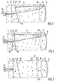
- - la figure 1 est une coupe médiane d'un composant réalisé selon l'invention et utilisant un réseau plan de diffraction,
- - la figure 2 est une figure correspondante pour un :omposant utilisant deux miroirs plans pour la séparation ies longueurs d'ondes, un miroir étant entièrement réfléchissant et l'autre étant un miroir sélectif à couches multidiélectriques,
- - la figure 3- représente une variante du dispositif de la figure 1, avec un élément intermédiaire lui-même en deux parties.
- FIG. 1 is a median section of a component produced according to the invention and using a plane diffraction grating,
- FIG. 2 is a corresponding figure for an: omposing using two plane mirrors for the separation of wavelengths, one mirror being entirely reflecting and the other being a selective mirror with multi-electric layers,
- - Figure 3 - shows a variant of the device of Figure 1, with an intermediate element itself in two parts.
En se référant tout d'abord à la figure 1, on verra que le dispositif représenté assure la même fonction que celui décrit à la figure 1 de l'addition publiée sous le n° 2 496 260, mais il est ici constitué en quatre éléments collés successivement les uns aux autres. L'élément 1 est un simple support des fibres optiques d'entrée et de sortie. L'élément 2 n'est que le support du réseau. L'élément 3 est un élément intermédiaire et l'élément 4 ne comporte que le miroir concave.Referring first to Figure 1, we will see that the device shown performs the same function as that described in Figure 1 of the addition published under No. 2,496,260, but it is here constituted by four elements glued successively to each other.
L'élément porte-fibres./pourra avantageusement être réalisé en utilisant le procédé décrit par le brevet français publié sous le n° 2 411 424 et concernant un connecteur de fibres optiques ; il suffira de réaliser un seul des deux blocs qui seraientnécessairespour un connecteur. Le brevet publié sous le n° 2 543 768 rappelle plus en détail une façon préférentielle de monter les fibres dans le bloc 1 et de faire affleurer leurs extrémités sur le plan de joint 12. L'élément porte-réseau 2 est un bloc transparent dont une face est polie pour constituer le plan de joint 12 avec l'élément 1 et dont l'autre face porte un réseau de diffraction plan 15. Le réseau 15 est réalisé de façon usuelle, c'est-à-dire par copie d'un réseau original gravé ou holographique, puis recouvrement d'une couche métallique réfléchissante. Pour permettre le passage sans déviation de la lumière en provenance des fibres 9 ou y aboutissant, il est -nécessaire de neutraliser localement le réseau 15 dans la zone 16 où il traverse le cône d'ouverture des fibres, c'est-à-dire la zone angulaire d'acceptance des rayons lumineux dans l'âme des fibres. Pour neutraliser le réseau dans cette zone 16, on procédera par photolithographie pour faire disparaître localement la couche réfléchissante. On observera que ceci n'entraîne aucune altération du réseau en dehors de la zone traitée et en particulier à la limite de cette zone. Par ailleurs, lorsque la face portant le réseau sera collée sur l'élément intermédiaire 3 de même indice que l'élément 2, il suffira d'utiliser comme colle une résine de même indice que celle de la résine formant le support du réseau 15, celle-ci étant elle-même choisie pour présenter un indice le plus proche possible de celui des deux blocs 2 et 3. Ainsi en remplissant les sillons du support de réseau la colle rétablira une continuité optique complète permettant le passage sans déviation des rayons lumineux.The fiber-holder element./ will advantageously be able to be produced using the method described by the French patent published under No. 2,411,424 and relating to a fiber optic connector; it will suffice to make only one of the two blocks which would be necessary for a connector. The patent published under No. 2,543,768 recalls in more detail a preferential way of mounting the fibers in the
L'élément intermédiaire 3 présente une face plane polie .pour collage sur le réseau 15 de l'élément 2 et une face sphériqué 34 pour former la surface de joint avec l'élément 4.The
Sur l'élément 4 la face opposée à la surface sphérique de joint 34 est elle-même une surface sphérique traitée pour former un miroir concave 8. L'élément7est en matériau d'indice n' différent de l'indice n des éléments 2 et 3. Ici n est inférieur à n' et la concavité de la surface 34 est opposée à celle du miroir 8. Si le choix des indices n et n' conduisait à prendre n inférieur à n' la concavité de la surface 34 devrait alors être de même sens que celle du miroir 8.On the
On notera que le fonctionnement optique de l'ensemble ainsi réalisé est tout à fait identique à celui de l'ensemble décrit dans le brevet 2 496 260. Dans le cas d'un fonctionnement en démultiplexeur par exemple, la lumière mélangée est amenée par l'une des fibres 9 dont l'extrémité est au foyer apparent du miroir 8, c'est-à-dire à l'emplacement de l'image de son foyer réel dans le dioptre 34. Après réfraction par le dioptre 34 les rayons issus de l'extrémité de la fibre sont donc renvoyés par le miroir 8 en un faisceau parallèle vers le réseau 15 qui le disperse en autant de faisceaux parallèles que de longueurs d'ondes dans la lumière mélangée. Par un chemin inverse chaque faisceau parallèle est focalisé sur l'extrémité d'une fibre de sortie 9. Mais ici le choix des indices différents pour les éléments 3 et 4 permet de corriger les aberrations du miroir sphérique 8 de telle sorte qu'il n'y aura inconvénient à utiliser un miroir sphérique beaucoup plus facile à réaliser industriellement qu'un miroir parabolique.It will be noted that the optical operation of the assembly thus produced is entirely identical to that of the assembly described in patent 2,496,260. In the case of operation in a demultiplexer for example, the mixed light is brought in by the 'one of the fibers 9 whose end is at the apparent focus of the
En outre, on a choisi pour les éléments 3 et 4 des aires de dispersion chromatique sensiblement égales permettant de ne pas introduire d'aberrations chromatiques. La courbure du dioptre sphérique 34 est alors choisie en fonction des indices n et n' des matériaux de façon à compenser également l'aberration sphérique du miroir.In addition, for
Tout ce qui précède est tout à fait transposable au cas de la figure 2 où l'élément 2 est traité sur la face 12 pour constituer un miroir plan 10, sauf bien entendu dans la zone faisant directement face aux extrémités des fibres 9. La face opposée 23, à l'exception de la zone centrale 16 qui coupe le cône d'ouverture des fibres, est traitée en couches multidiélectriques pour constituer un miroir sélectif ne réfléchissant qu'une certaine bande de longueurs d'ondes et laissant passer les autres sans déviation. Ainsi, le faisceau de lumière mélangée amené par l'une des fibres 9 dont l'extrémité sera au voisinage immédiat du foyer apparent du miroir 8 sera renvoyé en un faisceau parallèle vers les miroirs 10 et 11. Une partie de la lumière sera réfléchie par le miroir 11 et refocalisée par le miroir 8 vers une autre des fibres 9 ; l'autre partie de la lumière traversant le miroir 11 ne sera réfléchie que par le miroir 10 et renvoyée selon une direction différente vers le miroir 8 qui le focalisera vers une troisième fibre 9.All of the above is completely transposable to the case of FIG. 2 where the
On- se réfèrera enfin à la figure 3 qui montre une variante de réalisation facilitant le réglage du dispositif. Ici l'élément. intermédiaire 3 est en deux parties 31 et 32, toutes deux par exemple en un matériau de même indice n que l'élément 2, et séparées par un plan de joint 35. Pour les modes de réalisation selon les figures 1 et 2, le réglage d'alignement des fibres ne peut s'effectuer avant collage définitif que par glissement plan du bloc porte-fibres 1 sur le plan de joint 12. Dans la réalisation selon la figuré 3, on peut également régler avant collage l'ensemble 32-4 par rapport au bloc 31 et au reste du composant par glissement sur le plan de joint 35.Finally, reference is made to FIG. 3 which shows an alternative embodiment facilitating the adjustment of the device. Here the element. intermediate 3 is in two
On a réalisé un ensemble selon la figure 1 avec :
- - pour les éléments 2
et 3 un verre vendu sous la référence RGN6 par Schott,d'indice variant de 1,58015 pour une longueur d'onde de 875 nm à 1,58420 pour une longueur d'onde de 706,5 nm, - - pour
l'élément 4 un verre vendu sous la référence BK7 par Schottd'indice variant de 1,509326 pour une longueur d'onde de 875 nm à 1,51289 pour une longueur d'onde de 706,5 nm, - - un rayon de 130,19 mm pour la face réfléchissante du miroir 8,
- - un rayon de 115,50 mm pour
la surface sphérique 34, - - une distance de 63,826 mm entre le
plan 12 d'extrémité des fibres et le sommet de lasurface sphérique 34. Il en résulte une focale de 71,529 mm et, pour la plage de longueurs d'ondes de 875 à 706 nm le déplacement longitudinal du foyer en fonction de la longueur d'onde et de la hauteur d'incidence des rayons dans le système, pour des fibres d'ouverture ON = 0,29, est inférieur à ± 15 microns.
- - for
elements - - for
element 4, a glass sold under the reference BK7 by Schott with an index varying from 1.509326 for a wavelength of 875 nm to 1.51289 for a wavelength of 706.5 nm, - - a radius of 130.19 mm for the reflecting face of the
mirror 8, - - a radius of 115.50 mm for the
spherical surface 34, - - a distance of 63.826 mm between the
end plane 12 of the fibers and the apex of thespherical surface 34. This results in a focal length of 71.529 mm and, for the wavelength range of 875 to 706 nm the longitudinal displacement of the focal point as a function of the wavelength and of the height of incidence of the rays in the system, for fibers with an opening ON = 0.29, is less than ± 15 microns.
Dans une réalisation où le verre IRGN6 est remplacé par un verre yendu par le même fournisseur sous la référence PSK52,- le déplacement longitudinal est réduit à + 8 microns pour une focale de 72,137 mm.In an embodiment where the IRGN6 glass is replaced by a yendu glass by the same supplier under the reference PSK52, - the longitudinal displacement is reduced to + 8 microns for a focal length of 72.137 mm.
Bien entendu l'invention n'est pas strictement limitée aux modes de réalisation qui ont été décrits à simple titre d'exemple, mais elle couvre également les réalisations qui n'en différeraient que par des détails, par des variantes d'exécution ou pour par l'utilisation de moyens équivalents.Of course, the invention is not strictly limited to the embodiments which have been described simply by way of example, but it also covers the embodiments which would differ only in details, in variant embodiments or for by the use of equivalent means.
Claims (6)
caractérisé par le fait qu'il est constitué d'au moins quatre éléments transparents collés Les uns aux autres, successivement:
characterized in that it consists of at least four transparent elements glued to each other, successively:
Applications Claiming Priority (2)
| Application Number | Priority Date | Filing Date | Title |
|---|---|---|---|
| FR8504134A FR2579333B1 (en) | 1985-03-20 | 1985-03-20 | WAVELENGTH MULTIPLEXER-DEMULTIPLEXER CORRECTED FOR GEOMETRIC AND CHROMATIC ABERRATIONS |
| FR8504134 | 1985-03-20 |
Publications (2)
| Publication Number | Publication Date |
|---|---|
| EP0196963A1 true EP0196963A1 (en) | 1986-10-08 |
| EP0196963B1 EP0196963B1 (en) | 1989-07-26 |
Family
ID=9317396
Family Applications (1)
| Application Number | Title | Priority Date | Filing Date |
|---|---|---|---|
| EP86400573A Expired EP0196963B1 (en) | 1985-03-20 | 1986-03-18 | Wavelength multiplexer-demultiplexer corrected for geometric and chromatic aberrations |
Country Status (5)
| Country | Link |
|---|---|
| US (1) | US4819224A (en) |
| EP (1) | EP0196963B1 (en) |
| JP (1) | JPS61223712A (en) |
| DE (1) | DE3664688D1 (en) |
| FR (1) | FR2579333B1 (en) |
Cited By (2)
| Publication number | Priority date | Publication date | Assignee | Title |
|---|---|---|---|---|
| FR2680012A1 (en) * | 1991-07-30 | 1993-02-05 | Sextant Avionique | Spectral dispersion device |
| EP0962792A1 (en) * | 1998-06-04 | 1999-12-08 | Instruments S.A. | Compact multiplexer |
Families Citing this family (36)
| Publication number | Priority date | Publication date | Assignee | Title |
|---|---|---|---|---|
| US4930855A (en) * | 1988-06-06 | 1990-06-05 | Trw Inc. | Wavelength multiplexing of lasers |
| JPH02143203A (en) * | 1988-11-25 | 1990-06-01 | Ricoh Co Ltd | Optical multiplexer/demultiplexer element |
| US4934784A (en) * | 1989-03-20 | 1990-06-19 | Kaptron, Inc. | Hybrid active devices coupled to fiber via spherical reflectors |
| US5838504A (en) * | 1993-04-27 | 1998-11-17 | Asahi Kogaku Kogyo Kabushiki Kaisha | Prism and real image type view finder |
| IL107508A (en) * | 1993-11-05 | 1996-12-05 | Orbotech Ltd | Method and apparatus for recording on optically-sensitive media |
| US5768450A (en) * | 1996-01-11 | 1998-06-16 | Corning Incorporated | Wavelength multiplexer/demultiplexer with varied propagation constant |
| US6046854A (en) | 1996-02-09 | 2000-04-04 | Corning Incorporated | Multi-path interference filter with reflective surfaces |
| US5841583A (en) * | 1996-02-09 | 1998-11-24 | Corning Incorporated | Multi-path interference filter |
| US6111674A (en) * | 1996-02-23 | 2000-08-29 | Corning Incorporated | Multiple reflection multiplexer and demultiplexer |
| FR2765972B1 (en) * | 1997-07-11 | 1999-09-24 | Instruments Sa | WAVELENGTH-DISPERSION OPTICAL SYSTEM |
| US6271970B1 (en) * | 1997-12-13 | 2001-08-07 | Lightchip, Inc. | Wavelength division multiplexing/demultiplexing devices using dual homogeneous refractive index lenses |
| US6011884A (en) * | 1997-12-13 | 2000-01-04 | Lightchip, Inc. | Integrated bi-directional axial gradient refractive index/diffraction grating wavelength division multiplexer |
| US6404945B1 (en) | 1997-12-13 | 2002-06-11 | Lightchip, Inc. | Wavelength division multiplexing/demultiplexing devices using homogeneous refractive index lenses |
| US6243513B1 (en) | 1997-12-13 | 2001-06-05 | Lightchip, Inc. | Wavelength division multiplexing/demultiplexing devices using diffractive optic lenses |
| US6289155B1 (en) | 1997-12-13 | 2001-09-11 | Lightchip, Inc. | Wavelength division multiplexing/demultiplexing devices using dual high index of refraction crystalline lenses |
| US6236780B1 (en) | 1997-12-13 | 2001-05-22 | Light Chip, Inc. | Wavelength division multiplexing/demultiplexing devices using dual diffractive optic lenses |
| US6181853B1 (en) * | 1997-12-13 | 2001-01-30 | Lightchip, Inc. | Wavelength division multiplexing/demultiplexing device using dual polymer lenses |
| US6298182B1 (en) * | 1997-12-13 | 2001-10-02 | Light Chip, Inc. | Wavelength division multiplexing/demultiplexing devices using polymer lenses |
| US5999672A (en) * | 1997-12-13 | 1999-12-07 | Light Chip, Inc. | Integrated bi-directional dual axial gradient refractive index/diffraction grating wavelength division multiplexer |
| US6011885A (en) * | 1997-12-13 | 2000-01-04 | Lightchip, Inc. | Integrated bi-directional gradient refractive index wavelength division multiplexer |
| US6263135B1 (en) | 1997-12-13 | 2001-07-17 | Lightchip, Inc. | Wavelength division multiplexing/demultiplexing devices using high index of refraction crystalline lenses |
| CA2245389A1 (en) | 1998-08-24 | 2000-02-24 | Ilya Golub | Multiplexer/demultiplexer for wdm optical signals |
| US6275630B1 (en) | 1998-11-17 | 2001-08-14 | Bayspec, Inc. | Compact double-pass wavelength multiplexer-demultiplexer |
| US6108471A (en) * | 1998-11-17 | 2000-08-22 | Bayspec, Inc. | Compact double-pass wavelength multiplexer-demultiplexer having an increased number of channels |
| US6829096B1 (en) | 1999-02-25 | 2004-12-07 | Confluent Photonics Corporation | Bi-directional wavelength division multiplexing/demultiplexing devices |
| US6343169B1 (en) | 1999-02-25 | 2002-01-29 | Lightchip, Inc. | Ultra-dense wavelength division multiplexing/demultiplexing device |
| US6480648B1 (en) | 1999-02-25 | 2002-11-12 | Lightchip, Inc. | Technique for detecting the status of WDM optical signals |
| US6434299B1 (en) | 1999-06-01 | 2002-08-13 | Lightchip, Inc. | Wavelength division multiplexing/demultiplexing devices having concave diffraction gratings |
| US6415073B1 (en) | 2000-04-10 | 2002-07-02 | Lightchip, Inc. | Wavelength division multiplexing/demultiplexing devices employing patterned optical components |
| US6563977B1 (en) | 2000-06-27 | 2003-05-13 | Bayspec, Inc. | Compact wavelength multiplexer-demultiplexer providing low polarization sensitivity |
| US6901200B2 (en) * | 2000-12-22 | 2005-05-31 | Fiber Optic Network Solutions, Inc. | Module and housing for optical fiber distribution and DWDM equipment |
| CA2454631A1 (en) * | 2001-07-20 | 2003-01-30 | Essex Corporation | Method and apparatus for optical signal processing using an optical tapped delay line |
| CA2396410A1 (en) * | 2001-07-31 | 2003-01-31 | Nippon Sheet Glass Co., Ltd. | Optical module and method of forming the optical module |
| JP2003107278A (en) * | 2001-09-28 | 2003-04-09 | Nippon Sheet Glass Co Ltd | Optical module and its manufacturing method |
| TW589474B (en) * | 2003-04-29 | 2004-06-01 | Au Optronics Corp | Display panel with the integrated driver circuit |
| EP2083298B1 (en) | 2008-01-23 | 2017-05-10 | Yenista Optics | Optical device comprising a compact dispersing system |
Citations (6)
| Publication number | Priority date | Publication date | Assignee | Title |
|---|---|---|---|---|
| EP0083542A1 (en) * | 1981-12-24 | 1983-07-13 | Instruments S.A. | Wavelength selector |
| EP0099823A1 (en) * | 1982-07-16 | 1984-02-01 | Instruments S.A. | Compact wavelength multiplexer-demultiplexer with adaptive filtering |
| EP0102264A1 (en) * | 1982-07-16 | 1984-03-07 | Instruments S.A. | Arrangement for wavelength multiplexing or demultiplexing with optical isolation |
| EP0115443A2 (en) * | 1983-01-31 | 1984-08-08 | Kaptron Inc. | Fiber optics couplers |
| EP0121482A1 (en) * | 1983-03-31 | 1984-10-10 | Instruments S.A. | Wavelength multiplexer-demultiplexer and method of producing such an assembly |
| EP0121812A2 (en) * | 1983-03-16 | 1984-10-17 | Firma Carl Zeiss | Wavelength multiplexer-demultiplexer |
Family Cites Families (7)
| Publication number | Priority date | Publication date | Assignee | Title |
|---|---|---|---|---|
| US3897133A (en) * | 1973-03-05 | 1975-07-29 | David A Warner | Telescopic optical system |
| JPS556320A (en) * | 1978-06-27 | 1980-01-17 | Ritsuo Hasumi | Spectral module |
| FR2479981A1 (en) * | 1980-04-08 | 1981-10-09 | Instruments Sa | Inclined plane diffraction grating monochromator - has concave mirror and paraxial entry and wavelength-selective exit optical fibres |
| FR2496260A2 (en) * | 1980-12-12 | 1982-06-18 | Instruments Sa | Inclined plane diffraction grating monochromator - has concave mirror and paraxial entry and wavelength-selective exit optical fibres |
| DE3019956A1 (en) * | 1980-05-24 | 1981-12-03 | Ibm Deutschland Gmbh, 7000 Stuttgart | MODULAR, FIBER OPTICAL COMMUNICATION SYSTEM |
| FR2526961A1 (en) * | 1982-05-14 | 1983-11-18 | Cilas Alcatel | DEVICE FOR CONNECTING AN OPTICAL RADIATION GENERATOR AND AN OPTICAL WAVEGUIDE |
| FR2537808A1 (en) * | 1982-12-08 | 1984-06-15 | Instruments Sa | OPTICAL COMPONENT WITH SHARED FUNCTION FOR OPTICAL TELETRANSMISSIONS |
-
1985
- 1985-03-20 FR FR8504134A patent/FR2579333B1/en not_active Expired
-
1986
- 1986-03-18 DE DE8686400573T patent/DE3664688D1/en not_active Expired
- 1986-03-18 EP EP86400573A patent/EP0196963B1/en not_active Expired
- 1986-03-20 JP JP61063817A patent/JPS61223712A/en active Pending
- 1986-03-20 US US06/841,561 patent/US4819224A/en not_active Expired - Lifetime
Patent Citations (6)
| Publication number | Priority date | Publication date | Assignee | Title |
|---|---|---|---|---|
| EP0083542A1 (en) * | 1981-12-24 | 1983-07-13 | Instruments S.A. | Wavelength selector |
| EP0099823A1 (en) * | 1982-07-16 | 1984-02-01 | Instruments S.A. | Compact wavelength multiplexer-demultiplexer with adaptive filtering |
| EP0102264A1 (en) * | 1982-07-16 | 1984-03-07 | Instruments S.A. | Arrangement for wavelength multiplexing or demultiplexing with optical isolation |
| EP0115443A2 (en) * | 1983-01-31 | 1984-08-08 | Kaptron Inc. | Fiber optics couplers |
| EP0121812A2 (en) * | 1983-03-16 | 1984-10-17 | Firma Carl Zeiss | Wavelength multiplexer-demultiplexer |
| EP0121482A1 (en) * | 1983-03-31 | 1984-10-10 | Instruments S.A. | Wavelength multiplexer-demultiplexer and method of producing such an assembly |
Cited By (4)
| Publication number | Priority date | Publication date | Assignee | Title |
|---|---|---|---|---|
| FR2680012A1 (en) * | 1991-07-30 | 1993-02-05 | Sextant Avionique | Spectral dispersion device |
| EP0962792A1 (en) * | 1998-06-04 | 1999-12-08 | Instruments S.A. | Compact multiplexer |
| FR2779535A1 (en) * | 1998-06-04 | 1999-12-10 | Instruments Sa | COMPACT MULTIPLEXER |
| US6263134B1 (en) | 1998-06-04 | 2001-07-17 | Highwave Optical Technologies | Compact multiplexer |
Also Published As
| Publication number | Publication date |
|---|---|
| FR2579333B1 (en) | 1987-07-03 |
| US4819224A (en) | 1989-04-04 |
| JPS61223712A (en) | 1986-10-04 |
| EP0196963B1 (en) | 1989-07-26 |
| FR2579333A1 (en) | 1986-09-26 |
| DE3664688D1 (en) | 1989-08-31 |
Similar Documents
| Publication | Publication Date | Title |
|---|---|---|
| EP0196963B1 (en) | Wavelength multiplexer-demultiplexer corrected for geometric and chromatic aberrations | |
| EP0121482B1 (en) | Wavelength multiplexer-demultiplexer and method of producing such an assembly | |
| EP0138698B1 (en) | Optical wavelength division multiplexer-demultiplexer for bidirectional communication | |
| EP0275795B1 (en) | Division wavelength multiplexer/demultiplexer having an elliptical concave grating, and its use in integrated optics | |
| EP0083542B1 (en) | Wavelength selector | |
| EP0102264B1 (en) | Arrangement for wavelength multiplexing or demultiplexing with optical isolation | |
| FR2608785A1 (en) | DEVICE FOR CONNECTING OPTICAL FIBERS TO AN INTEGRATED OPTICAL CIRCUIT AND METHOD FOR PRODUCING THE SAME | |
| EP0782021A1 (en) | Arrayed waveguide grating optical demultiplexer | |
| EP0121962B1 (en) | Apparatus for optically coupling light guides | |
| EP0549406B1 (en) | Polarising beam splitter and its application in an imaging system | |
| EP0962792B1 (en) | Compact multiplexer | |
| EP0037787B1 (en) | Monochromator | |
| FR2765424A1 (en) | OPTICAL FIBER WAVELENGTH MULTIPLEXER-DEMULTIPLEXER | |
| EP0884615B1 (en) | Fibre optic wavelength division multiplexer-demultiplexer | |
| EP0811173B1 (en) | Wide-angle spectral rejector and method for making same | |
| FR2653879A1 (en) | Spectrograph with convex diffraction grating | |
| FR2706638A1 (en) | Chromatic time dispersion method, dispersive optical device, and optical fiber transmission system using the device | |
| EP1079215B1 (en) | High resolution infrared spectroscopic instrument | |
| EP3899458B1 (en) | Instrument with a plurality of optical channels | |
| EP0416989B1 (en) | Coupling device between optical transmission elements | |
| FR2532766A1 (en) | OPTICAL COUPLING DEVICE | |
| FR2496260A2 (en) | Inclined plane diffraction grating monochromator - has concave mirror and paraxial entry and wavelength-selective exit optical fibres | |
| CA2498349A1 (en) | Flat top optical filtering component | |
| FR2512614A1 (en) | Multiplexing procedure for fibre=optic signals - uses fabry-perot etalon both to encode and decode signals from differing wavelength optical sources | |
| EP0156687A1 (en) | Waveguide coupling device for wavelength multiplexing or demultiplexing |
Legal Events
| Date | Code | Title | Description |
|---|---|---|---|
| PUAI | Public reference made under article 153(3) epc to a published international application that has entered the european phase |
Free format text: ORIGINAL CODE: 0009012 |
|
| AK | Designated contracting states |
Kind code of ref document: A1 Designated state(s): BE CH DE FR GB LI |
|
| 17P | Request for examination filed |
Effective date: 19861104 |
|
| 17Q | First examination report despatched |
Effective date: 19880418 |
|
| GRAA | (expected) grant |
Free format text: ORIGINAL CODE: 0009210 |
|
| AK | Designated contracting states |
Kind code of ref document: B1 Designated state(s): BE CH DE FR GB LI |
|
| GBT | Gb: translation of ep patent filed (gb section 77(6)(a)/1977) | ||
| REF | Corresponds to: |
Ref document number: 3664688 Country of ref document: DE Date of ref document: 19890831 |
|
| PLBE | No opposition filed within time limit |
Free format text: ORIGINAL CODE: 0009261 |
|
| STAA | Information on the status of an ep patent application or granted ep patent |
Free format text: STATUS: NO OPPOSITION FILED WITHIN TIME LIMIT |
|
| 26N | No opposition filed | ||
| PGFP | Annual fee paid to national office [announced via postgrant information from national office to epo] |
Ref country code: BE Payment date: 19920312 Year of fee payment: 7 |
|
| PGFP | Annual fee paid to national office [announced via postgrant information from national office to epo] |
Ref country code: CH Payment date: 19920319 Year of fee payment: 7 |
|
| PG25 | Lapsed in a contracting state [announced via postgrant information from national office to epo] |
Ref country code: LI Effective date: 19930331 Ref country code: CH Effective date: 19930331 Ref country code: BE Effective date: 19930331 |
|
| BERE | Be: lapsed |
Owner name: S.A. INSTRUMENTS Effective date: 19930331 |
|
| REG | Reference to a national code |
Ref country code: CH Ref legal event code: PL |
|
| REG | Reference to a national code |
Ref country code: GB Ref legal event code: IF02 |
|
| REG | Reference to a national code |
Ref country code: FR Ref legal event code: TP Ref country code: FR Ref legal event code: CD |
|
| PGFP | Annual fee paid to national office [announced via postgrant information from national office to epo] |
Ref country code: FR Payment date: 20020307 Year of fee payment: 17 |
|
| PGFP | Annual fee paid to national office [announced via postgrant information from national office to epo] |
Ref country code: GB Payment date: 20020320 Year of fee payment: 17 |
|
| PGFP | Annual fee paid to national office [announced via postgrant information from national office to epo] |
Ref country code: DE Payment date: 20020328 Year of fee payment: 17 |
|
| REG | Reference to a national code |
Ref country code: GB Ref legal event code: 732E |
|
| PG25 | Lapsed in a contracting state [announced via postgrant information from national office to epo] |
Ref country code: GB Free format text: LAPSE BECAUSE OF NON-PAYMENT OF DUE FEES Effective date: 20030318 |
|
| PG25 | Lapsed in a contracting state [announced via postgrant information from national office to epo] |
Ref country code: DE Free format text: LAPSE BECAUSE OF NON-PAYMENT OF DUE FEES Effective date: 20031001 |
|
| GBPC | Gb: european patent ceased through non-payment of renewal fee |
Effective date: 20030318 |
|
| PG25 | Lapsed in a contracting state [announced via postgrant information from national office to epo] |
Ref country code: FR Free format text: LAPSE BECAUSE OF NON-PAYMENT OF DUE FEES Effective date: 20031127 |
|
| REG | Reference to a national code |
Ref country code: FR Ref legal event code: ST |