EP0115281B1 - Limit switch assembly - Google Patents
Limit switch assembly Download PDFInfo
- Publication number
- EP0115281B1 EP0115281B1 EP84100244A EP84100244A EP0115281B1 EP 0115281 B1 EP0115281 B1 EP 0115281B1 EP 84100244 A EP84100244 A EP 84100244A EP 84100244 A EP84100244 A EP 84100244A EP 0115281 B1 EP0115281 B1 EP 0115281B1
- Authority
- EP
- European Patent Office
- Prior art keywords
- switch
- box
- head
- switch box
- rubber hood
- Prior art date
- Legal status (The legal status is an assumption and is not a legal conclusion. Google has not performed a legal analysis and makes no representation as to the accuracy of the status listed.)
- Expired
Links
Images


Classifications
-
- H—ELECTRICITY
- H01—ELECTRIC ELEMENTS
- H01H—ELECTRIC SWITCHES; RELAYS; SELECTORS; EMERGENCY PROTECTIVE DEVICES
- H01H13/00—Switches having rectilinearly-movable operating part or parts adapted for pushing or pulling in one direction only, e.g. push-button switch
- H01H13/02—Details
- H01H13/04—Cases; Covers
- H01H13/06—Dustproof, splashproof, drip-proof, waterproof or flameproof casings
-
- H—ELECTRICITY
- H01—ELECTRIC ELEMENTS
- H01H—ELECTRIC SWITCHES; RELAYS; SELECTORS; EMERGENCY PROTECTIVE DEVICES
- H01H13/00—Switches having rectilinearly-movable operating part or parts adapted for pushing or pulling in one direction only, e.g. push-button switch
- H01H13/02—Details
- H01H13/12—Movable parts; Contacts mounted thereon
- H01H13/14—Operating parts, e.g. push-button
- H01H13/18—Operating parts, e.g. push-button adapted for actuation at a limit or other predetermined position in the path of a body, the relative movement of switch and body being primarily for a purpose other than the actuation of the switch, e.g. door switch, limit switch, floor-levelling switch of a lift
-
- H—ELECTRICITY
- H01—ELECTRIC ELEMENTS
- H01H—ELECTRIC SWITCHES; RELAYS; SELECTORS; EMERGENCY PROTECTIVE DEVICES
- H01H13/00—Switches having rectilinearly-movable operating part or parts adapted for pushing or pulling in one direction only, e.g. push-button switch
- H01H13/02—Details
- H01H13/04—Cases; Covers
- H01H13/06—Dustproof, splashproof, drip-proof, waterproof or flameproof casings
- H01H13/063—Casings hermetically closed by a diaphragm through which passes an actuating member
Definitions
- the present invention generally relates to a limit switch assembly and, more particularly, to a limit switch assembly of a type comprising a switch box having a built-in switch, and a head mounted on the switch box and having an actuator for actuating the switch.
- the intrusion of oil into the built-in switch by the capillary action may also take place through the set screws used to secure the switch in position within the switch box, thereby posing a problem similar to that described above. Furthermore, where the switch is secured in position within the switch box by the use of the set screws, impacts and/or vibrations applied exteriorly to the switch box tend to be transmitted to the built-in switch, and, in the worst it may happen, not only does the built-in switch fail to operate property, but also external wiring elements connected to respective terminal members of the built-in switch may separate from the terminal members.
- the rubber hood in a manner as shown in Fig. 9 of the accompanying drawings.
- the rubber hood generally identified by 34, is configured to substantially tightly receive therein the switch 33 contacting all of the surfaces of said switch including the surface thereof from which the push button protrudes outwards, but excluding the surface thereof from which terminal members protrude outwards.
- the switch 33 so covered by the rubber hood 34 is secured to a wall of the switch box 20 by means of screws 60 extending through respective mounting holes 33c defined in the switch 33 so as to extend completely through the thickness thereof.
- both the impact resistance and the dust proofness of the switch assembly may be improved.
- a worker engaged in the fabrication of the switch assembly will be forced to locate the mounting holes 33c exteriorly of the rubber hood 34 immediately before the screws 61 are inserted therethrough to secure the switch to the wall of the switch box 20.
- portions of the rubber hood adjacent the screws extending through the respective mounting holes may be inwardly compressed, as shown, as the screws are fastened, and accordingly, in the assembled condition, the switch 33 may happen to be secured in a manner tilted relative to the wall of the switch box 20.
- the operating position of the actuator for actuating the push button of the switch may deviate from a predetermined or required position to such an extent as to fail to properly engage an external driving element.
- GB-A-1 362196 discloses a push-button forming part of an alarm contact box.
- the switch is covered by elastomeric rear and front covers, the rear cover having a "top-hat” shaped central portion fitted with considerable clearance over the main portion of the switch and a collar fitted tightly around a base plate of the switch through which base plate the switch is mounted to the front plate of the housing of the alarm contact box by screws extending through the collar and clamping the same between the screws and the base plate of the switch and also between the base plate of the switch and the front plate of the housing.
- the front cover extending along the outer side of the base plate of the switch and over the push-button of the switch protruding from the base plate continues the rear cover and is clamped between the base plate of the switch and the front plate of the housing.
- a limit switch assembly according to the preamble of claim 1 in which the switch is fitted into a housing which covers all of the surfaces of the switch fitted therein except for the surface thereof from which the terminal members protrude.
- the housing is slideably supported by the outer switch box so as to be adjustable together with the switch fitted therein by an adjustment screw in a direction towards an actuator member of the switch assembly in order to obtain a definite spatial relationship between the actuator member and the push-button of the switch.
- An elastomeric cap-like membrane is interposed between and around the actuator and the push-button extending through said housing in order to seal the space around the push-button and the actuator member.
- US-A-4 342 894 describes a switch assembly comprising a push-button switch fitted into an elastomeric hood which has an expandable section provided for compensating an increase in the volume of the air within a sealed chamber surrounding the switch.
- the present invention has been developed with a view to substantially eliminating the disadvantages and inconveniences inherent in the prior art switch assemblies and has for its essential object to provide an improved switch assembly which has a high resistance to impacts and also a high dust proofness and which is reliable in operation.
- Another object of the present invention is to provide an improved switch assembly of the type referred to above, wherein means is provided to minimize change in pressure which would occur inside the head as a result of the movement of the actuator, thereby to facilitate a smooth movement thereof with the minimized driving force.
- a further object of the present invention is to provide an improved switch assembly of the type referred to above, which can be easily fabricated with no need to locate the mounting holes such as required in the prior art.
- a limit switch assembly embodying the present invention generally comprises a head 1 and a switch box 20 both connected together by means of a plurality of, for example, two, connecting bolts or screws 10.
- the head 1 has a tubular bearing member 2 protruding outwards from one surface thereof opposite the switch box 20.
- the plunger 3 is shown as having a roller member 5 rotatably mounted on an outer end thereof positioned exteriorly of the head 1 for engagement with an external driving element (not shown). The plunger 3 so supported by the bearing member 2 is normally biased to the projected position, as shown in Fig.
- a return spring 7 interposed between the plunger 3 and a generally rectangular spring seat member 6 secured to one surface of the head 1 opposite to the surface thereof from which the bearing member 2 projects outwardly and confronting the switch box 20.
- a safety spring 9 substantially housed within the plunger 3 and interposed between the plunger 3 and one end of the operating piece 8, the other end of said operating piece 8 protruding outwardly through an opening 6a in the spring seat member 6.
- the switch box 20 is a generally box-like container having a recess 21 defined therein leaving four continued side walls and a bottom wall as viewed in Fig. 2. Within the recess 21, there is disposed a sheet-like insulator 30 and a printed circuit board 31 both held against the bottom wall of the switch box 20.
- the built-in switch 33 is also accommodated within the recess 21 and positioned on one side of the printed circuit board 31 opposite to the insulator 30, but in the form as covered by a rubber hood 34.
- the rubber hood 34 shown in detail in Figs.
- 3 to 6 is of generally box-like configuration and is of such a design as to substantially cover all of the surfaces of the built-in switch 33 except for the surface thereof from which terminal members 34d protrude outwardly for external electrical connection.
- the surfaces of the built-in switch 33 covered by the rubber hood 34 include the surface 33a from which a push-button 33b extends outwardly and the opposite surfaces at which the opposite ends of each of the mounting holes 33c defined in the built-in switch are opened.
- the rubber hood 34 has a circumferential flange 34a protruding laterally outwardly therefrom in a plane generally in flush with the surface 33a of the built-in switch 33, which circumferential flange 34a is adapted to be clamped between the head 1 and the switch box 20.
- a portion of the rubber hood 34 confronting the surface 33b of the built-in switch 33 has a metal piece 50 inserted in alignment with the push button 33b on the one hand and with the operating piece 8 on the other hand.
- the rubber hood 34 has a cavity 34b defined therein at a location laterally of the built-in switch 33, which cavity 34b is in communication with the interior of the head 1 to substantially increase the volume of the interior of the head 1 forthe purpose as will be described later.
- the rubber hood 34 also has cutouts 34c formed therein at a portion thereof confronting the bottom of the recess 21 and generally in alignment with the respective openings of the mounting holes 33c, such that when and after the switch 33 having been covered by the rubber hood 34 has been inserted into the recess 21 of the switch box 20 through an opening 22 in said box 20 in a manner with the push button 33b located outside the switch box 20, spaced projections 23 integral with the bottom wall of the switch box 20 tightly fit into the associated holes 33c in the built-in switch 33 through the respective cutouts 34c to hold the switch 33 in position within the switch box 20.
- the switch 33 so accommodated in the switch box 20 is secured in position by a generally elongated stopper 35 press-fitted into the box 20 with its opposite ends tightly engaged against the opposite side walls of the box 20 as best shown in Fig. 8.
- steps 27 formed laterally of the respective projections 23 contact the lateral surface of the switch 33 through the associated cutouts 34c in the rubber hood 34 as best shown in Fig. 8, and, therefore, the extent to which the switch 33 is urged by the stopper 35 against the bottom wall of the box 20 can advantageously restricted by the contact between the steps 27 and the lateral surface of the switch 33.
- the side wall of the box 20 confronting the opening 22 is formed with a bore 25 into which a rubber bushing 37 having a cord 38 extending therethrough is sealingly plugged.
- the cord 38 has a plurality of insulated lead wires 38a, one connected to a grounding pin 39 inserted in the switch box 20 and the remaining lead wires connected respectively to the terminal members 33d.
- the switch box 20 is also formed with a window 26 at a corner area defined by the side wall with the bore 25 and the adjoining side wall, which window 26 is covered by a transparent lens member 40 so that a display element 32, such as a light emitting diode or the like, mounted on the printed circuit board 31 can be viewed from the outside of the switch box 20.
- the switch assembly of the construction described above can be fabricated in the following manner.
- the insulator 30 and the printed circuit board 31 are placed within the switch box 20 and, thereafter, the switch 33 covered with the rubber hood 34 is inserted into the box 20 through the opening 22.
- the stopper 35 is then inserted into the box 20 with its opposite ends sliding along the associated side walls of the box 20 to fix the switch 33 firmly in position within the box 20.
- a portion of the opening 22 around the switch 33 and exterior of the rubber hood 34 is closed by the circumferential flange 34a integral with the rubber hood 34, which circumferential flange 34a is then positioned exteriorly of the box 20 surrounding the opening 22 in the box 20.
- the cord 38 having the rubber bushing 37 thereon is inserted through the bore 25 so as to extend into the interior of the box 20 with the rubber bushing 37 tightly plugged into the bore 25.
- a synthetic filler material such as, for example, an epoxy resin, is poured into the recess 21 to solidify therein and the name plate 36 is then placed to close the opening of the box 20 leading into the recess 21. In this assembled condition so far described, even though foreign matters such as dusts and oil fall on the box 20, they do not reach the switch 33 and, thus, the switch 33 is protected from them.
- the switch assembly according to the present invention described with reference to and shown in Figs. 1 to 8 operates in a manner similar to a conventional limit switch assembly. That is to say, when the roller 5 contacts the external driving element, the plunger 3 is moved from the projected position towards the depressed position against the return spring 7, accompanied by the corresponding movement of the operating piece 8. As the operating piece 8 moves as urged by the safety spring 9, the end of the operating piece 8 adjacent the metal piece 50 protrudes the required distance outwardly from the opening 6a in the spring seat member 6 to depress the push button 33b through the metal piece 50. When the push button 33b is depressed, the switching state of the switch 33 changes and the display element 32 may be energized or deenergized to provide through the transparent lens element 40 a visual indication of a particular switching state of the switch 33.
- the compressed airwithin the head 1 may leak to such an extent that the pressure within the head 1 becomes equal to the atmospheric pressure.
- the driving force applied to the plunger 3 to maintain the latter in the depressed position is released when and after the pressure inside the head 1 has become equal to the atmospheric pressure
- the return movement of the plunger 3 back to the projected position by the action of the spring 7 may develop a negative pressure inside the head 1, imposing a resistance to the smooth movement of the plunger towards the projected position.
- This problem is also eliminated according to the present invention by the provision of the cavity 34b which, in this case, acts to minimize the development of the negative pressure.
- the switch since the switch is covered by the rubber hood, the switch is protected not only from the external foreign matters, but also from impacts. Therefore, the switch assembly as a whole has a dust-proof structure with an improved resistance to impacts. In addition, since no screw elements are employed to secure the switch in position, the switch assembly as a whole is relatively easy to fabricate with no possibility of the switch being displaced relative to the operating piece.
- the presence of the cavity in the rubber hood is advantageous in that the smooth movement of the plunger is assured at all times without being affected by the pressure which may be developed within the head.
- the actuator for the switch has been described and shown as comprised of the plunger and the operating piece, it may comprise a lever or any other actuator operable to push the push button of the switch exteriorly of the rubber hood.
- the use of the filler material although it is advantageous in that the internal parts can be protected and insulated, is not always essential to the present invention and may, therefore, be omitted.
- the switch has been described as inserted into the box through the opening defined in the box so as to confront the head, it may be loaded into the box through the opening which is subsequently closed by the name plate.
- the rubber hood may have holes in place of the cutouts 34c.
Abstract
Description
- The present invention generally relates to a limit switch assembly and, more particularly, to a limit switch assembly of a type comprising a switch box having a built-in switch, and a head mounted on the switch box and having an actuator for actuating the switch.
- Hitherto, numerous types of limit switch assemblies have been developed and placed in the market, some of them employing the actuator in the form of a plunger and some of them employing the actuator in the form of a lever or a combined lever and arm. In all of these prior art assemblies, not only are the head and the switch box connected together with an O-ring interposed therebetween, but the built-in switch is secured in position within the switch box by the use of set screws. Accordingly, it has been found that, even though the O-ring is interposed between the head and the switch box, the O-ring is not effective to avoid any possible intrusion of an undesirable fluid medium such as, for example, oil by the capillary action, and therefore, the built-in switch tends to fail to operate properly when wetted in contact with the fluid medium. In addition, according to the prior art, since the area of the switch from which a push button projects outward is exposed to the outside of the switch box before the head is mounted on the switch box with the actuator aligned with the push button, foreign matters such as dusts and oily substances tend to adhere to the push button which may ultimately result in the malfunctioning of the switch assembly as a whole.
- The intrusion of oil into the built-in switch by the capillary action may also take place through the set screws used to secure the switch in position within the switch box, thereby posing a problem similar to that described above. Furthermore, where the switch is secured in position within the switch box by the use of the set screws, impacts and/or vibrations applied exteriorly to the switch box tend to be transmitted to the built-in switch, and, in the worst it may happen, not only does the built-in switch fail to operate property, but also external wiring elements connected to respective terminal members of the built-in switch may separate from the terminal members.
- In view of the foregoing, it can be contemplated to use a rubber hood in a manner as shown in Fig. 9 of the accompanying drawings. Referring to Fig. 9, the rubber hood, generally identified by 34, is configured to substantially tightly receive therein the
switch 33 contacting all of the surfaces of said switch including the surface thereof from which the push button protrudes outwards, but excluding the surface thereof from which terminal members protrude outwards. Theswitch 33 so covered by therubber hood 34 is secured to a wall of theswitch box 20 by means ofscrews 60 extending throughrespective mounting holes 33c defined in theswitch 33 so as to extend completely through the thickness thereof. - In the contemplated arrangement shown in Fig. 9, both the impact resistance and the dust proofness of the switch assembly may be improved. However, a worker engaged in the fabrication of the switch assembly will be forced to locate the
mounting holes 33c exteriorly of therubber hood 34 immediately before thescrews 61 are inserted therethrough to secure the switch to the wall of theswitch box 20. Even if the switch will have been successfully secured to theswitch box 20, portions of the rubber hood adjacent the screws extending through the respective mounting holes may be inwardly compressed, as shown, as the screws are fastened, and accordingly, in the assembled condition, theswitch 33 may happen to be secured in a manner tilted relative to the wall of theswitch box 20. Once this happens, the operating position of the actuator for actuating the push button of the switch may deviate from a predetermined or required position to such an extent as to fail to properly engage an external driving element. - GB-A-1 362196 discloses a push-button forming part of an alarm contact box. The switch is covered by elastomeric rear and front covers, the rear cover having a "top-hat" shaped central portion fitted with considerable clearance over the main portion of the switch and a collar fitted tightly around a base plate of the switch through which base plate the switch is mounted to the front plate of the housing of the alarm contact box by screws extending through the collar and clamping the same between the screws and the base plate of the switch and also between the base plate of the switch and the front plate of the housing. The front cover extending along the outer side of the base plate of the switch and over the push-button of the switch protruding from the base plate continues the rear cover and is clamped between the base plate of the switch and the front plate of the housing.
- In FR-A-2 413 770 there is described a limit switch assembly according to the preamble of claim 1 in which the switch is fitted into a housing which covers all of the surfaces of the switch fitted therein except for the surface thereof from which the terminal members protrude. The housing is slideably supported by the outer switch box so as to be adjustable together with the switch fitted therein by an adjustment screw in a direction towards an actuator member of the switch assembly in order to obtain a definite spatial relationship between the actuator member and the push-button of the switch. An elastomeric cap-like membrane is interposed between and around the actuator and the push-button extending through said housing in order to seal the space around the push-button and the actuator member.
- US-A-4 342 894 describes a switch assembly comprising a push-button switch fitted into an elastomeric hood which has an expandable section provided for compensating an increase in the volume of the air within a sealed chamber surrounding the switch.
- Accordingly, the present invention has been developed with a view to substantially eliminating the disadvantages and inconveniences inherent in the prior art switch assemblies and has for its essential object to provide an improved switch assembly which has a high resistance to impacts and also a high dust proofness and which is reliable in operation.
- This object can be achieved by carrying out the features disclosed in the characterising part of claim 1.
- Another object of the present invention is to provide an improved switch assembly of the type referred to above, wherein means is provided to minimize change in pressure which would occur inside the head as a result of the movement of the actuator, thereby to facilitate a smooth movement thereof with the minimized driving force.
- A further object of the present invention is to provide an improved switch assembly of the type referred to above, which can be easily fabricated with no need to locate the mounting holes such as required in the prior art.
- These and other objects and features of the present invention will become apparent from the following detailed description of the preferred embodiment thereof taken in conjunction with reference to the accompanying drawings, in which:
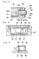
- Fig. 1 is a longitudinal sectional view of a limit switch assembly;
- Fig. 2 is an exploded view of the limit switch assembly shown in Fig. 1;
- Fig. 3 is a top plan view of a rubber hood used in the switch assembly shown in Fig. 1;
- Fig. 4 is a longitudinal sectional view of the rubber hood;
- Fig 5 is a cross-sectional view of the rubber hood taken along the line V-V in Fig. 4;
- Fig. 6 is a bottom plan view of the rubber hood;
- Fig. 7 is a cross-sectional view taken along the line VII-VII in Fig. 1;
- Fig. 8 is a cross-sectional view taken along the line VIII-VIII in Fig. 7; and
- Fig. 9 is a schematic sectional view illustrating the manner in which a built-in switch is secured in position by set screws.
- Before the description of the present invention proceeds, it is to be noted that like parts are designated by like reference numerals throughout the accompanying drawings.
- Referring first to Figs. 1 and 2, a limit switch assembly embodying the present invention generally comprises a head 1 and a
switch box 20 both connected together by means of a plurality of, for example, two, connecting bolts orscrews 10. - The head 1 has a tubular bearing member 2 protruding outwards from one surface thereof opposite the
switch box 20. Aplunger 3, forming a part of an actuator for a built-in switch 33 as will be described later, extends through the bearing member 2 for axial movement between projected and depressed positions, with an O-ring 4 interposed between theplunger 3 and the bearing member 2 so as to avoid any possible intrusion of foreign matters into the interior of the head 1. Theplunger 3 is shown as having aroller member 5 rotatably mounted on an outer end thereof positioned exteriorly of the head 1 for engagement with an external driving element (not shown). Theplunger 3 so supported by the bearing member 2 is normally biased to the projected position, as shown in Fig. 1, by areturn spring 7 interposed between theplunger 3 and a generally rectangularspring seat member 6 secured to one surface of the head 1 opposite to the surface thereof from which the bearing member 2 projects outwardly and confronting theswitch box 20. Axially slidably inserted within theplunger 3 is a generallyelongated operating piece 8 which is normally biased in a direction counter to theplunger 3 by a safety spring 9 substantially housed within theplunger 3 and interposed between theplunger 3 and one end of theoperating piece 8, the other end of saidoperating piece 8 protruding outwardly through an opening 6a in thespring seat member 6. - In the construction so far described, it will be readily seen that, when the
plunger 3 is moved towards the depressed position against thereturn spring 7 by the application of an external driving force thereto through theroller 5, the safety spring 9 tending to be axially inwardly compressed urges theoperating piece 8 to move in the same direction as theplunger 3 is moved, with the other end of saidoperating piece 8 consequently protruding a required distance outwardly from the opening 6a in thespring seat member 6. - The
switch box 20 is a generally box-like container having arecess 21 defined therein leaving four continued side walls and a bottom wall as viewed in Fig. 2. Within therecess 21, there is disposed a sheet-like insulator 30 and a printedcircuit board 31 both held against the bottom wall of theswitch box 20. The built-inswitch 33 is also accommodated within therecess 21 and positioned on one side of the printedcircuit board 31 opposite to theinsulator 30, but in the form as covered by arubber hood 34. Therubber hood 34, shown in detail in Figs. 3 to 6, is of generally box-like configuration and is of such a design as to substantially cover all of the surfaces of the built-inswitch 33 except for the surface thereof from which terminal members 34d protrude outwardly for external electrical connection. It is to be noted that the surfaces of the built-inswitch 33 covered by therubber hood 34 include thesurface 33a from which a push-button 33b extends outwardly and the opposite surfaces at which the opposite ends of each of themounting holes 33c defined in the built-in switch are opened. Therubber hood 34 has acircumferential flange 34a protruding laterally outwardly therefrom in a plane generally in flush with thesurface 33a of the built-inswitch 33, whichcircumferential flange 34a is adapted to be clamped between the head 1 and theswitch box 20. A portion of therubber hood 34 confronting thesurface 33b of the built-inswitch 33 has ametal piece 50 inserted in alignment with thepush button 33b on the one hand and with theoperating piece 8 on the other hand. Therubber hood 34 has acavity 34b defined therein at a location laterally of the built-inswitch 33, whichcavity 34b is in communication with the interior of the head 1 to substantially increase the volume of the interior of the head 1 forthe purpose as will be described later. Therubber hood 34 also hascutouts 34c formed therein at a portion thereof confronting the bottom of therecess 21 and generally in alignment with the respective openings of themounting holes 33c, such that when and after theswitch 33 having been covered by therubber hood 34 has been inserted into therecess 21 of theswitch box 20 through anopening 22 in saidbox 20 in a manner with thepush button 33b located outside theswitch box 20, spacedprojections 23 integral with the bottom wall of theswitch box 20 tightly fit into the associatedholes 33c in the built-inswitch 33 through therespective cutouts 34c to hold theswitch 33 in position within theswitch box 20. Theswitch 33 so accommodated in theswitch box 20 is secured in position by a generallyelongated stopper 35 press-fitted into thebox 20 with its opposite ends tightly engaged against the opposite side walls of thebox 20 as best shown in Fig. 8. In this condition,steps 27 formed laterally of therespective projections 23 contact the lateral surface of theswitch 33 through theassociated cutouts 34c in therubber hood 34 as best shown in Fig. 8, and, therefore, the extent to which theswitch 33 is urged by thestopper 35 against the bottom wall of thebox 20 can advantageously restricted by the contact between thesteps 27 and the lateral surface of theswitch 33. After theswitch 33 has been mounted and fixed in position within thebox 20, the opening of thebox 20 leading into therecess 21 is closed by aname plate 36 secured in position bystaking projections 24 integral with thebox 20 after they have passed through thename plate 36. - The side wall of the
box 20 confronting theopening 22 is formed with abore 25 into which a rubber bushing 37 having acord 38 extending therethrough is sealingly plugged. Thecord 38 has a plurality of insulatedlead wires 38a, one connected to agrounding pin 39 inserted in theswitch box 20 and the remaining lead wires connected respectively to theterminal members 33d. Theswitch box 20 is also formed with awindow 26 at a corner area defined by the side wall with thebore 25 and the adjoining side wall, whichwindow 26 is covered by atransparent lens member 40 so that adisplay element 32, such as a light emitting diode or the like, mounted on the printedcircuit board 31 can be viewed from the outside of theswitch box 20. - The switch assembly of the construction described above can be fabricated in the following manner. The
insulator 30 and the printedcircuit board 31 are placed within theswitch box 20 and, thereafter, theswitch 33 covered with therubber hood 34 is inserted into thebox 20 through theopening 22. Thestopper 35 is then inserted into thebox 20 with its opposite ends sliding along the associated side walls of thebox 20 to fix theswitch 33 firmly in position within thebox 20. At this time, a portion of theopening 22 around theswitch 33 and exterior of therubber hood 34 is closed by thecircumferential flange 34a integral with therubber hood 34, whichcircumferential flange 34a is then positioned exteriorly of thebox 20 surrounding theopening 22 in thebox 20. - Thereafter, the
cord 38 having therubber bushing 37 thereon is inserted through thebore 25 so as to extend into the interior of thebox 20 with therubber bushing 37 tightly plugged into thebore 25. After thelead wires 38a bundled in thecord 38 have been connected to thegrounding pin 39 and theterminal members 33d of theswitch 33, a synthetic filler material such as, for example, an epoxy resin, is poured into therecess 21 to solidify therein and thename plate 36 is then placed to close the opening of thebox 20 leading into therecess 21. In this assembled condition so far described, even though foreign matters such as dusts and oil fall on thebox 20, they do not reach theswitch 33 and, thus, theswitch 33 is protected from them. - When the head 1 having the actuator for the
switch 33 incorporated therein is mounted on theswitch box 20 with theoperating piece 8 aligned with thepush button 33b, and fastened thereto by means of the connectingscrews 10, thecircumferential flange 34a of therubber hood 34 is tightly clamped between the head 1 and thebox 20 to seal the joint therebetween, thereby completing the fabrication of the switch assembly according to the present invention. - It is to be noted that, since the
rubber hood 34 is positioned within thebox 20 together with theswitch 33 in the manner as hereinbefore described, thecircumferential flange 34a would neither deform nor displace and is uniformly clamped between the head 1 and thebox 20 and, therefore, the joint therebetween can be sealed tightly. - The switch assembly according to the present invention described with reference to and shown in Figs. 1 to 8 operates in a manner similar to a conventional limit switch assembly. That is to say, when the
roller 5 contacts the external driving element, theplunger 3 is moved from the projected position towards the depressed position against thereturn spring 7, accompanied by the corresponding movement of theoperating piece 8. As theoperating piece 8 moves as urged by the safety spring 9, the end of theoperating piece 8 adjacent themetal piece 50 protrudes the required distance outwardly from the opening 6a in thespring seat member 6 to depress thepush button 33b through themetal piece 50. When thepush button 33b is depressed, the switching state of theswitch 33 changes and thedisplay element 32 may be energized or deenergized to provide through the transparent lens element 40 a visual indication of a particular switching state of theswitch 33. - It is, however, to be noted that, as the
plunger 3 moves from the projected position towards the depressed position, air within the head 1 is compressed and, in such case, the relatively large driving force would be required to move theplunger 3 towards the depressed position. According to the present invention, this problem is eliminated by the provision of thecavity 34b which in essence increases the volume of the space that is compressed by the movement of theplunger 3, and therefore, no substantially increased driving force is required to move theplunger 3 towards the depressed position. - It is also to be noted that, when the
plunger 3 is maintained in the depressed position for a substantially long time, the compressed airwithin the head 1 may leak to such an extent that the pressure within the head 1 becomes equal to the atmospheric pressure. In the event that the driving force applied to theplunger 3 to maintain the latter in the depressed position is released when and after the pressure inside the head 1 has become equal to the atmospheric pressure, the return movement of theplunger 3 back to the projected position by the action of thespring 7 may develop a negative pressure inside the head 1, imposing a resistance to the smooth movement of the plunger towards the projected position. This problem is also eliminated according to the present invention by the provision of thecavity 34b which, in this case, acts to minimize the development of the negative pressure. - It is further noted that, even when the filler material of a type which solidifies upon cooling is poured into the
switch box 20, it will not penetrate into between therubber hood 34 and theswitch 33 and then towards thepush button 33b because therubber hood 34 contacts the peripheral surface of theswitch 33 by the action of its own elasticity thereby avoiding the penetration of the poured filler material. - From the foregoing full description of the present invention, it has now become clear that, since the switch is covered by the rubber hood, the switch is protected not only from the external foreign matters, but also from impacts. Therefore, the switch assembly as a whole has a dust-proof structure with an improved resistance to impacts. In addition, since no screw elements are employed to secure the switch in position, the switch assembly as a whole is relatively easy to fabricate with no possibility of the switch being displaced relative to the operating piece.
- Furthermore, the presence of the cavity in the rubber hood is advantageous in that the smooth movement of the plunger is assured at all times without being affected by the pressure which may be developed within the head.
- Although the present invention has fully been described in connection with the preferred embodiment thereof with reference to the accompanying drawings, it is to be noted that various changes and modifications are apparent to those skilled in the art. By way of example, although the actuator for the switch has been described and shown as comprised of the plunger and the operating piece, it may comprise a lever or any other actuator operable to push the push button of the switch exteriorly of the rubber hood.
- In addition, the use of the filler material although it is advantageous in that the internal parts can be protected and insulated, is not always essential to the present invention and may, therefore, be omitted.
- Furthermore, although the switch has been described as inserted into the box through the opening defined in the box so as to confront the head, it may be loaded into the box through the opening which is subsequently closed by the name plate. In this case, the rubber hood may have holes in place of the
cutouts 34c.
Claims (4)
Priority Applications (1)
| Application Number | Priority Date | Filing Date | Title |
|---|---|---|---|
| AT84100244T ATE26766T1 (en) | 1983-01-12 | 1984-01-11 | LIMIT SWITCH MOUNT. |
Applications Claiming Priority (2)
| Application Number | Priority Date | Filing Date | Title |
|---|---|---|---|
| JP1983003159U JPS59109028U (en) | 1983-01-12 | 1983-01-12 | limit switch |
| JP3159/83U | 1983-01-12 |
Publications (2)
| Publication Number | Publication Date |
|---|---|
| EP0115281A1 EP0115281A1 (en) | 1984-08-08 |
| EP0115281B1 true EP0115281B1 (en) | 1987-04-22 |
Family
ID=11549567
Family Applications (1)
| Application Number | Title | Priority Date | Filing Date |
|---|---|---|---|
| EP84100244A Expired EP0115281B1 (en) | 1983-01-12 | 1984-01-11 | Limit switch assembly |
Country Status (4)
| Country | Link |
|---|---|
| EP (1) | EP0115281B1 (en) |
| JP (1) | JPS59109028U (en) |
| AT (1) | ATE26766T1 (en) |
| DE (1) | DE3463315D1 (en) |
Cited By (1)
| Publication number | Priority date | Publication date | Assignee | Title |
|---|---|---|---|---|
| US8993903B2 (en) | 2007-07-23 | 2015-03-31 | Honeywell International Inc. | Sealed dual plunger switch assembly with simultaneity |
Families Citing this family (10)
| Publication number | Priority date | Publication date | Assignee | Title |
|---|---|---|---|---|
| IT209794Z2 (en) * | 1987-01-14 | 1988-11-04 | Cavis Cavetti Isolati Spa | PUSH BUTTON STRUCTURE, PARTICULARLY DESIGNED FOR ELECTRIC WINDOW OPERATION IN MOTOR VEHICLES. |
| IT1248935B (en) * | 1990-06-04 | 1995-02-11 | Sin Cros M D S R L | MOBILE CONTACT STRUCTURE, IMPLEMENTED THROUGH A WHEEL, PARTICULARLY DESIGNED FOR ENDOTHERMAL ENGINE SPINTEROGENES |
| DE4137484C2 (en) * | 1991-11-14 | 1995-06-29 | Roland Man Druckmasch | Mandrel |
| JP2557333Y2 (en) * | 1992-02-25 | 1997-12-10 | 株式会社ハーマン | Micro switch waterproof structure |
| FR2695707B1 (en) * | 1992-09-17 | 1995-10-20 | Parcellier Raymond | ELECTROMECHANICAL SAFETY APPARATUS FOR OVERLOAD PROTECTION. |
| DE4330917C1 (en) * | 1993-09-11 | 1995-02-16 | Merit Werk Merten & Co Kg | Switch for motor vehicles, in particular a reversing light switch and transmission switch or the like |
| DE19808060A1 (en) * | 1998-02-26 | 1999-09-09 | Euchner Gmbh & Co | Limit switch |
| DE10105630B4 (en) * | 2001-02-08 | 2011-09-22 | Volkswagen Ag | Rastierschalter |
| GB2562440B (en) * | 2016-03-11 | 2021-02-24 | Nitto Kohki Co | Belt-type grinding tool |
| CN107631449A (en) * | 2017-10-31 | 2018-01-26 | 广东美的制冷设备有限公司 | The emergency button case assembly and air conditioner room unit of air conditioner room unit |
Family Cites Families (6)
| Publication number | Priority date | Publication date | Assignee | Title |
|---|---|---|---|---|
| US3085140A (en) * | 1959-02-24 | 1963-04-09 | Robertshaw Fulton Controls Co | Encapsulated switch |
| CH399568A (en) * | 1962-08-03 | 1965-09-30 | Edwin Dr Guignard | Hermetically sealed housing with built-in, mechanically operated electrical switch |
| US3539738A (en) * | 1968-11-12 | 1970-11-10 | Gen Electric | Miniature industrial limit switch |
| GB1362196A (en) * | 1971-08-20 | 1974-07-30 | Ashworth & Co Ltd T | Electrical switches |
| FR2413770A1 (en) * | 1977-12-30 | 1979-07-27 | Telemecanique Electrique | WATERPROOF POSITION SWITCH |
| US4342894A (en) * | 1980-10-06 | 1982-08-03 | Robertshaw Controls Company | Electrical switch construction diaphragm seal therefor and methods of making the same |
-
1983
- 1983-01-12 JP JP1983003159U patent/JPS59109028U/en active Pending
-
1984
- 1984-01-11 DE DE8484100244T patent/DE3463315D1/en not_active Expired
- 1984-01-11 EP EP84100244A patent/EP0115281B1/en not_active Expired
- 1984-01-11 AT AT84100244T patent/ATE26766T1/en not_active IP Right Cessation
Cited By (1)
| Publication number | Priority date | Publication date | Assignee | Title |
|---|---|---|---|---|
| US8993903B2 (en) | 2007-07-23 | 2015-03-31 | Honeywell International Inc. | Sealed dual plunger switch assembly with simultaneity |
Also Published As
| Publication number | Publication date |
|---|---|
| EP0115281A1 (en) | 1984-08-08 |
| ATE26766T1 (en) | 1987-05-15 |
| DE3463315D1 (en) | 1987-05-27 |
| JPS59109028U (en) | 1984-07-23 |
Similar Documents
| Publication | Publication Date | Title |
|---|---|---|
| US4556768A (en) | Limit switch assembly | |
| EP0115281B1 (en) | Limit switch assembly | |
| US7938460B2 (en) | Latch release operating apparatus | |
| KR100224267B1 (en) | Case sealing structure and fabricating method thereof | |
| US7777141B2 (en) | Latch-release actuating apparatus | |
| US4885443A (en) | Sealed backlit switch assembly | |
| GB2053570A (en) | Fluid level detector | |
| JPH08316664A (en) | Structure for holding switch part board of small electronic apparatus | |
| KR20090040238A (en) | Pushbutton switch mounting structure | |
| US5836442A (en) | Door switch for vehicles | |
| EP0519239B1 (en) | Photoelectric switch sealed against infiltration of contaminants | |
| US4268734A (en) | Environmentally sealed toggle switch | |
| US4387282A (en) | Electrical switch assembly | |
| US5760356A (en) | Device assembly with sealed switch actuator interface | |
| US4701581A (en) | Housing including a test button secured thereto with a living hinge | |
| US4963704A (en) | Horn switch of steering wheel | |
| GB2252673A (en) | In field settable differential pressure switch assembly | |
| JPH11282360A (en) | Liquid crystal display device | |
| US3204069A (en) | Door switch assembly | |
| JP5021422B2 (en) | Waterproof structure of switch device | |
| JPH0785751A (en) | Pushbutton switch | |
| JPH09161593A (en) | Push-button device for waterproof electronic equipment | |
| JP2550817Y2 (en) | Moderation push-on switch | |
| JPS6142826A (en) | Pushbutton unit | |
| JPH0436516Y2 (en) |
Legal Events
| Date | Code | Title | Description |
|---|---|---|---|
| PUAI | Public reference made under article 153(3) epc to a published international application that has entered the european phase |
Free format text: ORIGINAL CODE: 0009012 |
|
| 17P | Request for examination filed |
Effective date: 19840119 |
|
| AK | Designated contracting states |
Designated state(s): AT BE CH DE FR GB IT LI LU NL SE |
|
| GRAA | (expected) grant |
Free format text: ORIGINAL CODE: 0009210 |
|
| AK | Designated contracting states |
Kind code of ref document: B1 Designated state(s): AT BE CH DE FR GB IT LI LU NL SE |
|
| REF | Corresponds to: |
Ref document number: 26766 Country of ref document: AT Date of ref document: 19870515 Kind code of ref document: T |
|
| REF | Corresponds to: |
Ref document number: 3463315 Country of ref document: DE Date of ref document: 19870527 |
|
| ITF | It: translation for a ep patent filed |
Owner name: STUDIO TORTA SOCIETA' SEMPLICE |
|
| ET | Fr: translation filed | ||
| PG25 | Lapsed in a contracting state [announced via postgrant information from national office to epo] |
Ref country code: LU Free format text: LAPSE BECAUSE OF NON-PAYMENT OF DUE FEES Effective date: 19880131 |
|
| PLBE | No opposition filed within time limit |
Free format text: ORIGINAL CODE: 0009261 |
|
| STAA | Information on the status of an ep patent application or granted ep patent |
Free format text: STATUS: NO OPPOSITION FILED WITHIN TIME LIMIT |
|
| 26N | No opposition filed | ||
| PGFP | Annual fee paid to national office [announced via postgrant information from national office to epo] |
Ref country code: NL Payment date: 19890131 Year of fee payment: 8 |
|
| PGFP | Annual fee paid to national office [announced via postgrant information from national office to epo] |
Ref country code: SE Payment date: 19900124 Year of fee payment: 7 |
|
| PGFP | Annual fee paid to national office [announced via postgrant information from national office to epo] |
Ref country code: AT Payment date: 19900125 Year of fee payment: 7 Ref country code: CH Payment date: 19900125 Year of fee payment: 7 |
|
| PGFP | Annual fee paid to national office [announced via postgrant information from national office to epo] |
Ref country code: FR Payment date: 19900126 Year of fee payment: 7 |
|
| PGFP | Annual fee paid to national office [announced via postgrant information from national office to epo] |
Ref country code: DE Payment date: 19900130 Year of fee payment: 7 |
|
| PGFP | Annual fee paid to national office [announced via postgrant information from national office to epo] |
Ref country code: LU Payment date: 19900131 Year of fee payment: 7 |
|
| PGFP | Annual fee paid to national office [announced via postgrant information from national office to epo] |
Ref country code: GB Payment date: 19901213 Year of fee payment: 8 |
|
| PG25 | Lapsed in a contracting state [announced via postgrant information from national office to epo] |
Ref country code: AT Effective date: 19910111 |
|
| PG25 | Lapsed in a contracting state [announced via postgrant information from national office to epo] |
Ref country code: SE Effective date: 19910112 |
|
| PG25 | Lapsed in a contracting state [announced via postgrant information from national office to epo] |
Ref country code: LI Effective date: 19910131 Ref country code: CH Effective date: 19910131 |
|
| PGFP | Annual fee paid to national office [announced via postgrant information from national office to epo] |
Ref country code: BE Payment date: 19910131 Year of fee payment: 8 |
|
| PG25 | Lapsed in a contracting state [announced via postgrant information from national office to epo] |
Ref country code: NL Effective date: 19910801 |
|
| NLV4 | Nl: lapsed or anulled due to non-payment of the annual fee | ||
| PG25 | Lapsed in a contracting state [announced via postgrant information from national office to epo] |
Ref country code: FR Effective date: 19910930 |
|
| REG | Reference to a national code |
Ref country code: CH Ref legal event code: PL |
|
| PG25 | Lapsed in a contracting state [announced via postgrant information from national office to epo] |
Ref country code: DE Effective date: 19911001 |
|
| REG | Reference to a national code |
Ref country code: FR Ref legal event code: ST |
|
| PG25 | Lapsed in a contracting state [announced via postgrant information from national office to epo] |
Ref country code: GB Effective date: 19920111 |
|
| PG25 | Lapsed in a contracting state [announced via postgrant information from national office to epo] |
Ref country code: BE Effective date: 19920131 |
|
| BERE | Be: lapsed |
Owner name: OMRON TATEISI ELECTRONICS CO. Effective date: 19920131 |
|
| GBPC | Gb: european patent ceased through non-payment of renewal fee | ||
| EUG | Se: european patent has lapsed |
Ref document number: 84100244.7 Effective date: 19910910 |