EP0115224A2 - Steuervorrichtung für Gangschaltgetriebe mit Stange auf gleitendem Kugelkopf - Google Patents
Steuervorrichtung für Gangschaltgetriebe mit Stange auf gleitendem Kugelkopf Download PDFInfo
- Publication number
- EP0115224A2 EP0115224A2 EP83402261A EP83402261A EP0115224A2 EP 0115224 A2 EP0115224 A2 EP 0115224A2 EP 83402261 A EP83402261 A EP 83402261A EP 83402261 A EP83402261 A EP 83402261A EP 0115224 A2 EP0115224 A2 EP 0115224A2
- Authority
- EP
- European Patent Office
- Prior art keywords
- rod
- transverse
- lever
- ball joint
- link
- Prior art date
- Legal status (The legal status is an assumption and is not a legal conclusion. Google has not performed a legal analysis and makes no representation as to the accuracy of the status listed.)
- Granted
Links
Images
Classifications
-
- F—MECHANICAL ENGINEERING; LIGHTING; HEATING; WEAPONS; BLASTING
- F16—ENGINEERING ELEMENTS AND UNITS; GENERAL MEASURES FOR PRODUCING AND MAINTAINING EFFECTIVE FUNCTIONING OF MACHINES OR INSTALLATIONS; THERMAL INSULATION IN GENERAL
- F16H—GEARING
- F16H61/00—Control functions within control units of change-speed- or reversing-gearings for conveying rotary motion ; Control of exclusively fluid gearing, friction gearing, gearings with endless flexible members or other particular types of gearing
- F16H61/26—Generation or transmission of movements for final actuating mechanisms
- F16H61/34—Generation or transmission of movements for final actuating mechanisms comprising two mechanisms, one for the preselection movement, and one for the shifting movement
-
- F—MECHANICAL ENGINEERING; LIGHTING; HEATING; WEAPONS; BLASTING
- F16—ENGINEERING ELEMENTS AND UNITS; GENERAL MEASURES FOR PRODUCING AND MAINTAINING EFFECTIVE FUNCTIONING OF MACHINES OR INSTALLATIONS; THERMAL INSULATION IN GENERAL
- F16H—GEARING
- F16H59/00—Control inputs to control units of change-speed- or reversing-gearings for conveying rotary motion
- F16H59/02—Selector apparatus
- F16H59/04—Ratio selector apparatus
- F16H59/042—Ratio selector apparatus comprising a final actuating mechanism
Definitions
- the invention relates to gearbox control devices for motor vehicles, devices comprising an operating lever carried, at a point relatively distant from the gearbox, by a spherical bearing secured to the body of the vehicle, and connected by the same longitudinal rod with two mobile elements of the gearbox.
- the first of these mobile elements is connected by a first link to a substantially vertical selection lever secured to the rod, so that a transverse tilting of the operating lever selects the ratios of the gearbox.
- the second movable element is itself connected by a second link to a lever for returning a vertical axis, a transverse arm of which is connected to the rod by a ball joint, so that a longitudinal tilting of the operating lever achieves the passage of reports.
- the latter is carried on the one hand by the ball joint connecting it to the return lever and, on the other hand, by a transverse axis connecting it to the operating lever so that a transverse tilting thereof causes the rod to pivot about its axis.
- This arrangement has the disadvantage of causing a significant transverse curvature of the longitudinal movements of the lever, during the passage of the reports, because the longitudinal displacements of the rod are accompanied by slight transverse inclinations due to the fact that the ball joint connecting it to the lever , as well as the articulation connecting the selection lever to the first link, describe arcs of a circle, all the more curved as this link, the rod and the transverse arm of the return lever are shorter for the purpose of lightness and compactness of the device.
- the invention aims to reduce this drawback by providing a gearbox control device in which any tilting of the operating lever, during the passage of a gear, takes place in a longitudinal plane, without transverse bending, and which however be simple and space-saving.
- the invention relates to a control device of the aforementioned type, comprising an operating lever carried, at a point relatively distant from the gearbox, by a spherical bearing secured to the body of the vehicle, and connected by a same longitudinal rod with two mobile elements of the gearbox, on each of which is articulated a transverse link, one of these links being attacked by a vertical selection lever secured to the rod, while the other is attacked, to shifting gears, by a vertical axis return lever, a transverse arm of which is connected by a ball joint to the rod, and the rod being further articulated on a third transverse link connecting it to a substantially fixed point of the vehicle and, at its end opposite the connecting rods, on a transverse axis secured to the operating lever.
- the ball joint is movable relative to the rod in a transverse direction substantially parallel to the rods and to the transverse arm of the return lever.
- the ball joint comprises a ball joint fixed on the transverse arm of the return lever, and an externally cylindrical seat mounted to slide in a transverse bore of the rod.
- This bore is in particular the housing inside a tubular part fixed to the rod, for example by welding.
- the ball joint is arranged in the vicinity of a line joining the centers of the joints connecting the rod to the third link and to the operating lever.
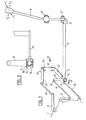
- FIG. 1 shows a device for controlling the gearbox 1 of a vehicle, this device being adapted to successively move two mobile elements, 2, 3 of the gearbox by respective transverse displacements (arrows F1, F ' 1 ) and longitudinal (arrows F 2 , F' 2 ) of an operating lever 4 which is substantially vertical and relatively distant from the gearbox 1.
- the lever 4 is carried by a spherical bearing 5 secured to the body of the vehicle, and is articulated on one end of a longitudinal rod 6 by means of a transverse axis 7 secured to the lever and mounted in a yoke 8 d end of the rod.
- the other end of the rod 6 carries a tubular part 9 with a horizontal transverse axis from which a vertical lever 10, known as the selection lever, leaves, these four parts 6, 8, 9 and 10 being in particular metallic and assembled by welding.
- the tubular part or sleeve 9 and the opposite end of the lever 10 are each fitted with a ball joint 11, 12, on which one of two substantially parallel and horizontal transverse rods, 13, 14, is articulated. substantially equal feeders and respectively connected to the gearbox 1 and the movable element 2.
- a seat 15 externally cylindrical but internally spherical, which cooperates with a ball joint 16 integral with the transverse horizontal arm 17 of a return lever 18.
- the lever 18 also includes a vertical axis 19 which pivots in a bearing 20 fixed to the vehicle body and a longitudinal arm 21 connected to the movable element 3 by a link transverse 22.
- the rod 6 is thus carried on one side by the fixed spherical bearing 5, by means of the lever 4 and the transverse axis 7, and on the other side by the bearing 20, by means of the arm 17 and of the ball joint 16.
- the transverse holding of the rod 6 is ensured at one end by the link 13 and at the other by the lever 4 which is constantly retained substantially in the same radial plane to the rod 6 as the lever 10, by mounting the transverse axis 7 in the yoke 8.
- the ball joint 16 describes a horizontal arc centered on the pivot axis of the return lever 18 and drives its seat 15 which slides in the bore of the tubular part 9 held transversely by the link 13. Consequently, the connection between the arm 17 and the rod 6 does not induce any transverse movement of this rod.
- the selection lever 10 moves with the rod 6 while always remaining parallel to its selected direction, and the ball joints 11 and 12 describe substantially parallel horizontal arcs of the circle since the links 13 and 14 are parallel and of equal or slightly different lengths .
- the translation of the lever 10 is therefore slightly curved.
- the operating lever 4 being in the same radial plane to the rod as the lever 10, also remains parallel to its selected direction and in fact does not undergo any undesirable transverse tilting during the passage of a gear. In other words, the tilting of the lever 4 takes place in a longitudinal plane without transverse curvature.
- the link 13 could, as a variant, connect the rod 6 to a fixed part of the vehicle body.
- the arrangement shown, where this link connects the rod 6 to a part of the gearbox is however preferable in the case where the box 1 is fixed to the body with the interposition of elastic supports allowing slight relative transverse movements between them, because these displacements are accompanied by relative displacements of the tubular piece 9 and of the ball joint 15, 16, without influ ink the chosen position of the other members and in particular of the operating lever.
- the transverse movements of the gearbox cause, via the links 13 and 14, a transverse translation of the lever 10 which, being integral with the sleeve 9, slides with it on the ball joint 15, 16.
- This lever 10 still remains parallel to its selected direction.
- the operating lever 4 in other words, this lever is not subject to untimely transverse movements during the relative movements between the gearbox and the vehicle body.
Landscapes
- Engineering & Computer Science (AREA)
- General Engineering & Computer Science (AREA)
- Mechanical Engineering (AREA)
- Gear-Shifting Mechanisms (AREA)
- Arrangement Or Mounting Of Control Devices For Change-Speed Gearing (AREA)
Applications Claiming Priority (2)
| Application Number | Priority Date | Filing Date | Title |
|---|---|---|---|
| FR8219671 | 1982-11-24 | ||
| FR8219671A FR2536554A1 (fr) | 1982-11-24 | 1982-11-24 | Dispositif de commande de boite de vitesses avec tige sur rotule coulissante |
Publications (3)
| Publication Number | Publication Date |
|---|---|
| EP0115224A2 true EP0115224A2 (de) | 1984-08-08 |
| EP0115224A3 EP0115224A3 (en) | 1984-08-22 |
| EP0115224B1 EP0115224B1 (de) | 1987-03-18 |
Family
ID=9279469
Family Applications (1)
| Application Number | Title | Priority Date | Filing Date |
|---|---|---|---|
| EP19830402261 Expired EP0115224B1 (de) | 1982-11-24 | 1983-11-23 | Steuervorrichtung für Gangschaltgetriebe mit Stange auf gleitendem Kugelkopf |
Country Status (3)
| Country | Link |
|---|---|
| EP (1) | EP0115224B1 (de) |
| DE (1) | DE3370386D1 (de) |
| FR (1) | FR2536554A1 (de) |
Cited By (4)
| Publication number | Priority date | Publication date | Assignee | Title |
|---|---|---|---|---|
| EP0273874A3 (en) * | 1986-02-04 | 1988-07-20 | Fiat Auto S.P.A. | Control device for a motor vehicle gearbox |
| EP0441248A1 (de) * | 1990-02-01 | 1991-08-14 | Iveco Magirus Aktiengesellschaft | Vorrichtung zum Schalten des Getriebes eines Kraftfahrzeuges |
| EP0448526A1 (de) * | 1990-03-20 | 1991-09-25 | FIAT AUTO S.p.A. | Einrichtung zur Betätigung eines Kraftfahrzeuggetriebes |
| CN112428469A (zh) * | 2020-11-10 | 2021-03-02 | 谢良育 | 一塑胶胶制品的生产工艺 |
Families Citing this family (4)
| Publication number | Priority date | Publication date | Assignee | Title |
|---|---|---|---|---|
| IT1175789B (it) * | 1984-06-20 | 1987-07-15 | Alfa Romeo Auto Spa | Dispositivo per il comando manuale del cambio di velocita' di un autoveicolo |
| FR2581152B1 (fr) * | 1985-04-26 | 1987-07-03 | Renault | Dispositif de transformation de mouvement pour commande interne de boite de vitesses. |
| FR2696254B1 (fr) * | 1992-09-29 | 1994-12-30 | Peugeot | Tringlerie de commande du changement de vitesses d'un véhicule automobile. |
| FR2696983B1 (fr) * | 1992-10-19 | 1995-01-27 | Peugeot | Tringlerie de commande du changement de vitesses d'un véhicule automobile. |
Family Cites Families (6)
| Publication number | Priority date | Publication date | Assignee | Title |
|---|---|---|---|---|
| FR85376E (fr) * | 1964-03-02 | 1965-07-30 | Citroen Sa Andre | Commande à distance de boîte de vitesses |
| FR1399437A (fr) * | 1964-06-25 | 1965-05-14 | Zahnradfabrik Friedrichshafen | Dispositif de commande de changement de vitesse pour boîte de vitesses de véhicules automobiles |
| FR91733E (fr) * | 1966-02-01 | 1968-08-02 | Publicite Francaise | Dispositif de commande d'une boîte de vitesses de véhicule automobile |
| FR1475771A (fr) * | 1966-02-01 | 1967-04-07 | Publicite Francaise | Dispositif de commande d'une boîte de vitesses de véhicule automobile |
| FR2345306A1 (fr) * | 1976-03-26 | 1977-10-21 | Renault | Dispositif de commande de boite de vitesses |
| FR2520134A1 (fr) * | 1982-01-18 | 1983-07-22 | Peugeot | Dispositif de commande de boite de vitesses |
-
1982
- 1982-11-24 FR FR8219671A patent/FR2536554A1/fr active Granted
-
1983
- 1983-11-23 EP EP19830402261 patent/EP0115224B1/de not_active Expired
- 1983-11-23 DE DE8383402261T patent/DE3370386D1/de not_active Expired
Cited By (4)
| Publication number | Priority date | Publication date | Assignee | Title |
|---|---|---|---|---|
| EP0273874A3 (en) * | 1986-02-04 | 1988-07-20 | Fiat Auto S.P.A. | Control device for a motor vehicle gearbox |
| EP0441248A1 (de) * | 1990-02-01 | 1991-08-14 | Iveco Magirus Aktiengesellschaft | Vorrichtung zum Schalten des Getriebes eines Kraftfahrzeuges |
| EP0448526A1 (de) * | 1990-03-20 | 1991-09-25 | FIAT AUTO S.p.A. | Einrichtung zur Betätigung eines Kraftfahrzeuggetriebes |
| CN112428469A (zh) * | 2020-11-10 | 2021-03-02 | 谢良育 | 一塑胶胶制品的生产工艺 |
Also Published As
| Publication number | Publication date |
|---|---|
| EP0115224A3 (en) | 1984-08-22 |
| DE3370386D1 (en) | 1987-04-23 |
| FR2536554A1 (fr) | 1984-05-25 |
| FR2536554B1 (de) | 1985-03-15 |
| EP0115224B1 (de) | 1987-03-18 |
Similar Documents
| Publication | Publication Date | Title |
|---|---|---|
| EP0084751B1 (de) | Handsteuereinrichtung für Gangschaltung mit Abriegelung des Rückwärtsgangs | |
| FR2812612A1 (fr) | Derailleur avant motorise de bicyclette | |
| EP0171318B1 (de) | Einrichtung für die Regelung der Neigung von Scheinwerfern für Kraftfahrzeuge | |
| EP0115224B1 (de) | Steuervorrichtung für Gangschaltgetriebe mit Stange auf gleitendem Kugelkopf | |
| EP0072464B1 (de) | Handsteuervorrichtung für die Gänge eines Wechselgetriebes | |
| FR2663266A1 (fr) | Dispositif de liaison d'une roue directrice a la caisse d'un vehicule automobile. | |
| EP0444994A1 (de) | Verstellbare Lenksäule | |
| EP0560645B1 (de) | Gangschalthebelvorrichtung, insbesondere für Kraftfahrzeuge | |
| EP0084472B1 (de) | Verstelleinrichtung für Schaltgetriebe | |
| EP0571274A1 (de) | Feststellbrems-Steuervorrichtung | |
| EP1538067A1 (de) | Kraftfahrzeugachse und Stellglied für solche Achse | |
| FR2566342A1 (fr) | Dispositif pour la commande manuelle de la boite de vitesses d'un vehicule automobile | |
| EP0751322A1 (de) | Fahrzeug-Gangschalthebel mit Kraftaufnehmer | |
| FR2792580A1 (fr) | Dispositif de changement de vitesse | |
| EP0007861B1 (de) | Verstellvorrichtung für einen Rückblickspiegel, insbesondere für Fahrzeuge | |
| FR2732661A1 (fr) | Dispositif de reglage en position d'une colonne de direction et du tableau de bord d'un vehicule automobile | |
| FR2792579A1 (fr) | Dispositif de changement de vitesse | |
| FR2598127A1 (fr) | Dispositif de reglage de l'orientation du reflecteur d'un projecteur de vehicule automobile | |
| FR2696254A1 (fr) | Tringlerie de commande du changement de vitesses d'un véhicule automobile. | |
| FR2863534A1 (fr) | Articulation de bras mecanique et bras pourvu de cette articulation | |
| FR2503072A1 (fr) | Timonerie de direction a cremaillere | |
| FR2909197A3 (fr) | Agencement pour un levier de commande de changement de vitesses comportant une coupelle hemispherique. | |
| FR2720365A1 (fr) | Ensemble de direction pour roues avant de véhicule automobile. | |
| FR2800019A1 (fr) | Dispositif de commande d'une boite de vitesses situee sous le volant | |
| WO2016142595A1 (fr) | Dispositif de rappel vers une position de point mort d'une commande externe d'une boîte de vitesses |
Legal Events
| Date | Code | Title | Description |
|---|---|---|---|
| PUAI | Public reference made under article 153(3) epc to a published international application that has entered the european phase |
Free format text: ORIGINAL CODE: 0009012 |
|
| PUAL | Search report despatched |
Free format text: ORIGINAL CODE: 0009013 |
|
| AK | Designated contracting states |
Designated state(s): DE GB IT |
|
| AK | Designated contracting states |
Designated state(s): DE GB IT |
|
| 17P | Request for examination filed |
Effective date: 19840712 |
|
| 17Q | First examination report despatched |
Effective date: 19860630 |
|
| ITF | It: translation for a ep patent filed | ||
| GRAA | (expected) grant |
Free format text: ORIGINAL CODE: 0009210 |
|
| AK | Designated contracting states |
Kind code of ref document: B1 Designated state(s): DE GB IT |
|
| REF | Corresponds to: |
Ref document number: 3370386 Country of ref document: DE Date of ref document: 19870423 |
|
| PLBE | No opposition filed within time limit |
Free format text: ORIGINAL CODE: 0009261 |
|
| STAA | Information on the status of an ep patent application or granted ep patent |
Free format text: STATUS: NO OPPOSITION FILED WITHIN TIME LIMIT |
|
| 26N | No opposition filed | ||
| REG | Reference to a national code |
Ref country code: GB Ref legal event code: 746 |
|
| ITPR | It: changes in ownership of a european patent |
Owner name: OFFERTA DI LICENZA AL PUBBLICO |
|
| ITTA | It: last paid annual fee | ||
| PGFP | Annual fee paid to national office [announced via postgrant information from national office to epo] |
Ref country code: DE Payment date: 20011019 Year of fee payment: 19 |
|
| PGFP | Annual fee paid to national office [announced via postgrant information from national office to epo] |
Ref country code: GB Payment date: 20011116 Year of fee payment: 19 |
|
| REG | Reference to a national code |
Ref country code: GB Ref legal event code: IF02 |
|
| PG25 | Lapsed in a contracting state [announced via postgrant information from national office to epo] |
Ref country code: GB Free format text: LAPSE BECAUSE OF NON-PAYMENT OF DUE FEES Effective date: 20021123 |
|
| PG25 | Lapsed in a contracting state [announced via postgrant information from national office to epo] |
Ref country code: DE Free format text: LAPSE BECAUSE OF NON-PAYMENT OF DUE FEES Effective date: 20030603 |
|
| GBPC | Gb: european patent ceased through non-payment of renewal fee |