EP0114985B1 - System for interfacing remote functional units to a terminal unit - Google Patents
System for interfacing remote functional units to a terminal unit Download PDFInfo
- Publication number
- EP0114985B1 EP0114985B1 EP83112246A EP83112246A EP0114985B1 EP 0114985 B1 EP0114985 B1 EP 0114985B1 EP 83112246 A EP83112246 A EP 83112246A EP 83112246 A EP83112246 A EP 83112246A EP 0114985 B1 EP0114985 B1 EP 0114985B1
- Authority
- EP
- European Patent Office
- Prior art keywords
- optical
- circuit
- signal
- functional units
- electrical signals
- Prior art date
- Legal status (The legal status is an assumption and is not a legal conclusion. Google has not performed a legal analysis and makes no representation as to the accuracy of the status listed.)
- Expired
Links
Images


Classifications
-
- H—ELECTRICITY
- H04—ELECTRIC COMMUNICATION TECHNIQUE
- H04B—TRANSMISSION
- H04B10/00—Transmission systems employing electromagnetic waves other than radio-waves, e.g. infrared, visible or ultraviolet light, or employing corpuscular radiation, e.g. quantum communication
- H04B10/80—Optical aspects relating to the use of optical transmission for specific applications, not provided for in groups H04B10/03 - H04B10/70, e.g. optical power feeding or optical transmission through water
- H04B10/801—Optical aspects relating to the use of optical transmission for specific applications, not provided for in groups H04B10/03 - H04B10/70, e.g. optical power feeding or optical transmission through water using optical interconnects, e.g. light coupled isolators, circuit board interconnections
Definitions
- the present invention relates to a circuit interfacing one or more remote functional units to a terminal unit utilizing a closed chamber as an inter-unit optical communications link.
- Any data processing terminal device ranging from a simple calculator to a complex point-of- sale terminal, can be viewed as a combination of functional units (controllers, printers, displays, etc.), each of which has a dedicated function to perform as well as a need to exchange data and control signals with at least some of the other functional units.
- functional units controllers, printers, displays, etc.
- the functional units have been linked through electrical wires, usually in the form of electrical cables.
- Cables have known disadvantages. Cables usually represent a significant portion of the component cost of a terminal device. The time and labor required to assemble terminal devices with electrical cables are also normally significant. Moreover, electrical cables are susceptible to electric noise or stray signals which can produce errors in the data or control signals being transmitted between functional units.
- optical fibers be used to provide communications links between the functional units.
- Optical fibers are less susceptible to noise or stray signals than electrical cables, but cost more and are harder to work with during terminal assembly operations.
- US-A-4 063 083 discloses a system having between functional units an optical link in which a single beam of optical energy is transmitted along a straight path within a closed chamber from one pluggable card to the next. At each card the optical energy may be detected, modified and retransmitted to the next card along the path. Lenses are included for maintaining the beam focus.
- each interface circuit would include both an optical emitter and an optical detector in communication with the optical chamber.
- EP-A-0 033 445 discloses an interface for communication between an optical bus system and an electrical bus system.
- the optical system includes an optical chamber having light emitters and light detectors interfacing to the chamber.
- a CPU, a memory and other devices are connected to the electrical bus.
- Serializer/Deserializer, Address Decoder, Clock, and Bus Switching units control the flow of electrical data from the electrical bus to the light emitters and from the light detectors to the electrical bus.
- EP-A-0 108 989 which is cited in accordance with Article 54(3) EPC, discloses a hybrid coupler for optical transmission of information between a plurality of subscribers.
- electrical signals from optical detectors positioned at the receiving end of optical signal transmitting cables are distributed in parallel through electrical wires and amplifiers to optical emitters providing optical signals to the transmitting end of optical signal transmitting cables.
- US-A-4 176 401 discloses an interface for the stations of a closed loop data system.
- An interface includes an input line from the previous station in the loop, an output line to the next station in the loop and input and output lines to the station associated with the interface.
- Photo-couplers in the interface include a light emitting diode and a phototransistor, the electrical output of two photo-couplers being connected in parallel across the output line to the next station.
- One of these photo-couplers is connected to the output of the station associated with the interface and inhibits signals from the other photo-coupler, connected to the input line from the previous station, to be sent to the next station while the station associated with the interface is transmitting.
- the invention relates to an improved circuit interfacing one or more functional units to a terminal unit which also has one or more integrated functional units which communicate optically by means of signals propagated through an optical closed chamber.
- the interface circuit of the invention as claimed uses relatively few components and requires relatively little space within the optical chamber in order to perform its intended function.
- the present invention pertains to a circuit for providing an interface between remote functional units and a terminal unit.
- a remote functional unit is considered to be any unit which is connected to the terminal unit through a signal-carrying cable.
- Displays, bar code scanners, produce scales, etc. are examples of typical remote functional units for a terminal unit used in a supermarket/retail store environment.
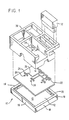
- the terminal unit 11 includes a base 10 with solid floor 12 and vertical sidewalls 14, 16, 18 and 20.
- a power distribution board 22 rests on the sidewalls of the base 10.
- the four sidewalls and floor of base 10, together with the bottom surface of power distribution board 22 define a closed optical chamber 13 which serves as the distribution medium for optical data and control signals. Details as to the manner in which the signals are distributed through the optical chamber are provided later.
- the power distribution board 22 includes a plurality of power connectors, such as connector 24, and a plurality of optically transparent ports, such as opening 26.
- the connectors 24 are linked through a pattern of conductors 28 which distribute AC or DC voltages generated by a power supply (not shown).
- the power distribution board 22 also carries the components required to interface remote units to the terminal unit 11. A more complete description of these components is provided below.
- a frame 30 overlies the power distribution board 22 and rests directly on the base 10.
- Frame 30 includes a number of rectangular openings or bays for receiving largely self-contained terminal functional units, such as terminal functional units 32.
- Each terminal functional unit which is plugged into one of the bays in frame 30 includes an optical transducer.
- the transducer includes a light emitting device which can inject optical energy directly into the optical chamber 13 through aligned openings in the power distribution board 22 and the frame 30. Openings 34 and 36 are examples of these aligned openings.
- Each terminal functional unit also includes a power connector which can be mated to one of the power connectors on power distribution board 22 through a rectangular opening in the floor of frame 30. Opening 38 is an example of such a rectangular opening.
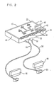
- FIG 2 is a rear perspective view including the base 10 and the power distribution board 22.
- the interface circuit includes a circuit card 40 which includes a primary electrooptical transducer 42.
- the transducer 42 includes an optical detector 54 ( Figure 3) which responds to optical energy being propagated through the closed optical chamber 13 to generate an electrical signal which is representative of said optical energy. This electrical signal is distributed via a signal distributing circuit to each of several connectors 44 on the power distribution board 22. More details about the nature of this connection are provided later.
- the primary transducer 42 also includes a light emitting device 60 (Figure 3) capable of injecting optical energy into the optical chamber. In a preferred embodiment, the light emitting device 60 in primary transducer 42 is driven by a single signal which is a logical OR of the signals received from all of the remote functional units ( Figure 5).
- each remote functional unit 46 and 48 is connected to the terminal unit through a signal carrying cable 50 having suitable connectors 52, 55 at each end.
- each of the remote functional units 46 and 48 has an optical/ physical interface which allows that unit either to be plugged directly into the power distribution board 22 within the frame 30 ( Figure 1) or into the terminating connector 55 at one end of a signal-carrying cable 50.
- the use of such a standardized interface allows a functional unit to be used either as an integral component of the terminal unit or as a remotely located component.
- Figure 3 is a schematic diagram of a preferred form of the signal distributing circuit between the optical chamber 13 and the remote functional units, such as units 46, 48.
- the primary optical transducer 42 mounted on circuit card 40 ( Figure 2) includes a single light detector 54 which detects optical energy being propagated through the optical chamber 13. The output of the light detector 54 modulates the current provided by a current source 56 to provide an electrical signal representative of the optical signal in the chamber 13. The modulated electrical signal is used to drive a plurality of emitters 43 associated with different secondary transducers 45 at the connector areas 44. The same signal is applied or broadcast to all of the emitters 43 of the secondary transducers 45 without regard to the identity of the remote functional unit for whom the signal is ultimately intended. Each of these emitters 43 supplies the same signal to its associated remote functional unit through the associated signal carrying cable 50.
- the signal carrying cables 50 are fiber optic cables which transmit the optical signals generated by the associated light emitter 43.
- Each of the secondary transducers 45 also includes a detector element 47 capable of detecting signals received from the associated remote functional unit.
- the detector 47 is responsive to optical signals transmitted through the associated signal-carrying cable 50.
- the output of each of the detectors 47 is logically ORed at an input to an emitted driver circuit 58 which drives the single light emitter 60 of the primary transducer 42.
- the detectors 47 in the secondary transducers 45 and the emitter driver circuit 58 perform a concentrating function so that the primary transducer 42 is driven by a single signal regardless of the number of remote functional units which are attached to the terminal. Thus, all remote functional units interface with the optical chamber 13 through a single primary transducer 42.
- Figure 3 indicates that modulated current provided by current source 56 is supplied to each of the secondary transducer emitters 43 in series.
- Figure 4 shows a preferred form of this circuit.
- the output of light detector 54 controls a shunt transistor 62 which is connected in parallel with the series of secondary transducer emitters 43.
- Each secondary transducer emitter 4 include a Zener diode 64 shunting a light emitting diode 66.
- the light emitting diode 66 in each such circuit may be connected permanently in parallel with the associated Zener diode 64.
- the voltage drop across a light emitting diode 66 is normally small enough to allow the associated Zener diode 64 to appear as an open circuit. If, however, a light emitting diode 66 fails in an open circuit mode or is removed, for example by unplugging the cable, full voltage provided by source 56 will be imposed across the associated Zener diode 64, causing the Zener diode to break down and supply the full current to the remaining light emitting diodes 66 in the series circuit. Thus, the removal or failure of one of the light emitting diodes 66 does not affect the remaining light emitting diodes in series therewith.
- Shunt transistor 62 acts. as a simple signal modulator for the current provided by source 56. If the signal supplied by light detector 54 to the base of shunt transistor 62 is high enough, the transistor switches into a conductive state and current provided by source 56 is diverted directly to ground; in this case the light emitting diodes 66 would be shut off. If the detector signal is low, shunt transistor 62 is non-conductive and current supplied by source 56 flows along the series current path through each of the tight emitting diodes 66. The combination of the current source 56, the transistor 62 and the individual light emitting diode 66 provides a broadcast function; that is, a single signal detected in the optical chamber is broadcast to all attached remote functional units.
- FIG. 5 is one embodiment of circuitry capable of concentrating signals received from the functional units.
- This concentrator circuitry includes a current source 70 and one (or more) switching transistor 72 connected in parallel with a light emitting diode 74 and a carrier-dissipating diode 76.
- the base drive signal for the transistor 72 is provided by an OR-NOT gate 78 having multiple inputs from the detectors 47 receiving signals from the remote functional units. If any functional unit provides a high level signal, transistor 72 is biased into a non-conductive state and current is supplied to the light emitting diode 74 which emits light into the closed optical chamber 13.
Description
- The present invention relates to a circuit interfacing one or more remote functional units to a terminal unit utilizing a closed chamber as an inter-unit optical communications link.
- Any data processing terminal device, ranging from a simple calculator to a complex point-of- sale terminal, can be viewed as a combination of functional units (controllers, printers, displays, etc.), each of which has a dedicated function to perform as well as a need to exchange data and control signals with at least some of the other functional units.
- Conventionally, the functional units have been linked through electrical wires, usually in the form of electrical cables. Cables have known disadvantages. Cables usually represent a significant portion of the component cost of a terminal device. The time and labor required to assemble terminal devices with electrical cables are also normally significant. Moreover, electrical cables are susceptible to electric noise or stray signals which can produce errors in the data or control signals being transmitted between functional units.
- To avoid some of these problems, proposals have been made that optical fibers be used to provide communications links between the functional units. Optical fibers are less susceptible to noise or stray signals than electrical cables, but cost more and are harder to work with during terminal assembly operations.
- To overcome some of the known problems of electrical or optical cables, US-A-4 063 083 discloses a system having between functional units an optical link in which a single beam of optical energy is transmitted along a straight path within a closed chamber from one pluggable card to the next. At each card the optical energy may be detected, modified and retransmitted to the next card along the path. Lenses are included for maintaining the beam focus.
- While the approach disclosed in the above mentioned patent avoids some of the problems inherent in the use of electrical or optical cables, certain other problems seem to be created. In fact, the terminal device would have to be carefully assembled to maintain the proper beam alignment. Also, the arrangement is somewhat inflexible in that the cards must be arranged in series along the beam path.
- The straightforward approach to interfacing remote functional units to the remainder of a closed chamber communications terminal would be to provide complete, self-contained interface circuits for all of the remote functional units. That is, each interface circuit would include both an optical emitter and an optical detector in communication with the optical chamber.
- There are, however, drawbacks to this straightforward approach. The cost of having complete, self-contained interface circuits for all remote units would be high. Moreover, it would very likely be difficult to physically locate all of the necessary interface circuits in the optical chamber in locations in which optical signals could be received at suitable levels and in which one unit would not "shade" or partially block signal paths to one or more other remote functional units.
- Other approaches to interfacing remote functional units have been proposed.
- EP-A-0 033 445 discloses an interface for communication between an optical bus system and an electrical bus system. The optical system includes an optical chamber having light emitters and light detectors interfacing to the chamber. A CPU, a memory and other devices are connected to the electrical bus. Serializer/Deserializer, Address Decoder, Clock, and Bus Switching units control the flow of electrical data from the electrical bus to the light emitters and from the light detectors to the electrical bus.
- EP-A-0 108 989, which is cited in accordance with Article 54(3) EPC, discloses a hybrid coupler for optical transmission of information between a plurality of subscribers. In the coupler, electrical signals from optical detectors positioned at the receiving end of optical signal transmitting cables are distributed in parallel through electrical wires and amplifiers to optical emitters providing optical signals to the transmitting end of optical signal transmitting cables.
- US-A-4 176 401 discloses an interface for the stations of a closed loop data system. An interface includes an input line from the previous station in the loop, an output line to the next station in the loop and input and output lines to the station associated with the interface. Photo-couplers in the interface include a light emitting diode and a phototransistor, the electrical output of two photo-couplers being connected in parallel across the output line to the next station. One of these photo-couplers is connected to the output of the station associated with the interface and inhibits signals from the other photo-coupler, connected to the input line from the previous station, to be sent to the next station while the station associated with the interface is transmitting.
- The invention relates to an improved circuit interfacing one or more functional units to a terminal unit which also has one or more integrated functional units which communicate optically by means of signals propagated through an optical closed chamber.
- The interface circuit of the invention as claimed uses relatively few components and requires relatively little space within the optical chamber in order to perform its intended function.
- One way of carrying out the invention is described in detail hereinafter with reference to drawings, in which:
- Figure 1 is an exploded, perspective view of a terminal unit in which the present invention could be practiced;
- Figure 2 is a simplified, rear perspective of such a terminal unit showing some of the details of the interface circuit's physical structure;
- Figure 3 is a schematic diagram of one embodiment of the signal distributing circuit;
- Figure 4 is a schematic diagram of the distributor or emitter section of the interface circuit; and
- Figure 5 is a schematic diagram of a concentrator of signals.
- The present invention pertains to a circuit for providing an interface between remote functional units and a terminal unit. A remote functional unit is considered to be any unit which is connected to the terminal unit through a signal-carrying cable. Displays, bar code scanners, produce scales, etc., are examples of typical remote functional units for a terminal unit used in a supermarket/retail store environment.
- With reference to Figure 1, the
terminal unit 11 includes abase 10 withsolid floor 12 andvertical sidewalls power distribution board 22 rests on the sidewalls of thebase 10. The four sidewalls and floor ofbase 10, together with the bottom surface ofpower distribution board 22 define a closedoptical chamber 13 which serves as the distribution medium for optical data and control signals. Details as to the manner in which the signals are distributed through the optical chamber are provided later. - The
power distribution board 22 includes a plurality of power connectors, such asconnector 24, and a plurality of optically transparent ports, such as opening 26. Theconnectors 24 are linked through a pattern ofconductors 28 which distribute AC or DC voltages generated by a power supply (not shown). Thepower distribution board 22 also carries the components required to interface remote units to theterminal unit 11. A more complete description of these components is provided below. - A
frame 30 overlies thepower distribution board 22 and rests directly on thebase 10.Frame 30 includes a number of rectangular openings or bays for receiving largely self-contained terminal functional units, such as terminalfunctional units 32. Each terminal functional unit which is plugged into one of the bays inframe 30 includes an optical transducer. The transducer includes a light emitting device which can inject optical energy directly into theoptical chamber 13 through aligned openings in thepower distribution board 22 and theframe 30.Openings power distribution board 22 through a rectangular opening in the floor offrame 30.Opening 38 is an example of such a rectangular opening. - Figure 2 is a rear perspective view including the
base 10 and thepower distribution board 22. The interface circuit includes acircuit card 40 which includes a primaryelectrooptical transducer 42. Thetransducer 42 includes an optical detector 54 (Figure 3) which responds to optical energy being propagated through the closedoptical chamber 13 to generate an electrical signal which is representative of said optical energy. This electrical signal is distributed via a signal distributing circuit to each ofseveral connectors 44 on thepower distribution board 22. More details about the nature of this connection are provided later. Theprimary transducer 42 also includes a light emitting device 60 (Figure 3) capable of injecting optical energy into the optical chamber. In a preferred embodiment, thelight emitting device 60 inprimary transducer 42 is driven by a single signal which is a logical OR of the signals received from all of the remote functional units (Figure 5). - For purposes of illustration, only two remote
functional units connectors 44 available on the rear edge of thepower distribution board 22. Each remote functional unit (for example functional unit 48) is connected to the terminal unit through asignal carrying cable 50 havingsuitable connectors functional units power distribution board 22 within the frame 30 (Figure 1) or into the terminatingconnector 55 at one end of a signal-carryingcable 50. The use of such a standardized interface allows a functional unit to be used either as an integral component of the terminal unit or as a remotely located component. - Figure 3 is a schematic diagram of a preferred form of the signal distributing circuit between the
optical chamber 13 and the remote functional units, such asunits optical transducer 42 mounted on circuit card 40 (Figure 2) includes asingle light detector 54 which detects optical energy being propagated through theoptical chamber 13. The output of thelight detector 54 modulates the current provided by acurrent source 56 to provide an electrical signal representative of the optical signal in thechamber 13. The modulated electrical signal is used to drive a plurality ofemitters 43 associated with differentsecondary transducers 45 at theconnector areas 44. The same signal is applied or broadcast to all of theemitters 43 of thesecondary transducers 45 without regard to the identity of the remote functional unit for whom the signal is ultimately intended. Each of theseemitters 43 supplies the same signal to its associated remote functional unit through the associatedsignal carrying cable 50. - The
signal carrying cables 50 are fiber optic cables which transmit the optical signals generated by the associatedlight emitter 43. - Each of the
secondary transducers 45 also includes adetector element 47 capable of detecting signals received from the associated remote functional unit. In the preferred embodiment, thedetector 47 is responsive to optical signals transmitted through the associated signal-carryingcable 50. The output of each of thedetectors 47 is logically ORed at an input to an emitteddriver circuit 58 which drives thesingle light emitter 60 of theprimary transducer 42. Thedetectors 47 in thesecondary transducers 45 and theemitter driver circuit 58 perform a concentrating function so that theprimary transducer 42 is driven by a single signal regardless of the number of remote functional units which are attached to the terminal. Thus, all remote functional units interface with theoptical chamber 13 through a singleprimary transducer 42. - Figure 3 indicates that modulated current provided by
current source 56 is supplied to each of thesecondary transducer emitters 43 in series. Figure 4 shows a preferred form of this circuit. The output oflight detector 54 controls ashunt transistor 62 which is connected in parallel with the series ofsecondary transducer emitters 43. Each secondary transducer emitter 4 include aZener diode 64 shunting alight emitting diode 66. Thelight emitting diode 66 in each such circuit may be connected permanently in parallel with the associatedZener diode 64. There are, however, advantages to having thelight emitting diode 66 provided as an integral part of theconnector 52 at the terminal end of the signal-carryingcable 50. The possible physical incorporation of thelight emitting diode 66 into the cable/connector structure is represented by thesymbols 68. - In an arrangement of the type described in Figure 4, the voltage drop across a
light emitting diode 66 is normally small enough to allow the associatedZener diode 64 to appear as an open circuit. If, however, alight emitting diode 66 fails in an open circuit mode or is removed, for example by unplugging the cable, full voltage provided bysource 56 will be imposed across the associatedZener diode 64, causing the Zener diode to break down and supply the full current to the remaininglight emitting diodes 66 in the series circuit. Thus, the removal or failure of one of thelight emitting diodes 66 does not affect the remaining light emitting diodes in series therewith. -
Shunt transistor 62 acts. as a simple signal modulator for the current provided bysource 56. If the signal supplied bylight detector 54 to the base ofshunt transistor 62 is high enough, the transistor switches into a conductive state and current provided bysource 56 is diverted directly to ground; in this case thelight emitting diodes 66 would be shut off. If the detector signal is low,shunt transistor 62 is non-conductive and current supplied bysource 56 flows along the series current path through each of the tight emittingdiodes 66. The combination of thecurrent source 56, thetransistor 62 and the individuallight emitting diode 66 provides a broadcast function; that is, a single signal detected in the optical chamber is broadcast to all attached remote functional units. - Figure 5 is one embodiment of circuitry capable of concentrating signals received from the functional units. This concentrator circuitry includes a
current source 70 and one (or more) switchingtransistor 72 connected in parallel with alight emitting diode 74 and a carrier-dissipatingdiode 76. The base drive signal for thetransistor 72 is provided by an OR-NOT gate 78 having multiple inputs from thedetectors 47 receiving signals from the remote functional units. If any functional unit provides a high level signal,transistor 72 is biased into a non-conductive state and current is supplied to thelight emitting diode 74 which emits light into the closedoptical chamber 13. Obviously, it is possible for more than one functional unit to provide a drive signal at any given time; to avoid garbled, overlapping signals, the machine architecture and programming has to establish certain protocols which assure that only one functional unit provides a responsive signal at a time. The establishment of such protocols, however, is beyond the scope of the present invention. - For maximum flexibility in locating remote functional units, necessary AC or DC voltages could be provided through the
cables 50 to the remote functional units using separate electrical conductors from the data/control signal conductors in the cable.
Claims (10)
Applications Claiming Priority (2)
| Application Number | Priority Date | Filing Date | Title |
|---|---|---|---|
| US45607183A | 1983-01-06 | 1983-01-06 | |
| US456071 | 1983-01-06 |
Publications (2)
| Publication Number | Publication Date |
|---|---|
| EP0114985A1 EP0114985A1 (en) | 1984-08-08 |
| EP0114985B1 true EP0114985B1 (en) | 1987-10-28 |
Family
ID=23811306
Family Applications (1)
| Application Number | Title | Priority Date | Filing Date |
|---|---|---|---|
| EP83112246A Expired EP0114985B1 (en) | 1983-01-06 | 1983-12-06 | System for interfacing remote functional units to a terminal unit |
Country Status (3)
| Country | Link |
|---|---|
| EP (1) | EP0114985B1 (en) |
| JP (1) | JPS59126340A (en) |
| DE (1) | DE3374237D1 (en) |
Families Citing this family (2)
| Publication number | Priority date | Publication date | Assignee | Title |
|---|---|---|---|---|
| ES2138963T3 (en) * | 1992-06-02 | 2000-02-01 | Procter & Gamble | COMPOSITIONS FOR CLOTHING WHITENING. |
| US5387994A (en) * | 1994-02-14 | 1995-02-07 | Thermo King Corporation | Communications adapter for converting wire-based communication to wireless communication |
Citations (2)
| Publication number | Priority date | Publication date | Assignee | Title |
|---|---|---|---|---|
| EP0033445A1 (en) * | 1980-01-17 | 1981-08-12 | Siemens Aktiengesellschaft | Passive bus system for decentrally structured multicomputer systems, especially for multimicrocomputer systems |
| EP0108989A2 (en) * | 1982-11-12 | 1984-05-23 | Richard Hirschmann Radiotechnisches Werk | Arrangement for optical information transmission between a plurality of subscribers |
Family Cites Families (4)
| Publication number | Priority date | Publication date | Assignee | Title |
|---|---|---|---|---|
| US4176401A (en) * | 1978-03-01 | 1979-11-27 | Owens-Corning Fiberglas Corporation | Digital communications system |
| GB2069196B (en) * | 1980-02-05 | 1984-03-21 | Marconi Co Ltd | Processor arrangement |
| JPS56149843A (en) * | 1980-04-23 | 1981-11-19 | Nec Corp | Optical loop data transmission system |
| JPS5784637A (en) * | 1980-11-17 | 1982-05-27 | Ricoh Co Ltd | Optical loop transmission system |
-
1983
- 1983-12-06 EP EP83112246A patent/EP0114985B1/en not_active Expired
- 1983-12-06 DE DE8383112246T patent/DE3374237D1/en not_active Expired
- 1983-12-12 JP JP58232901A patent/JPS59126340A/en active Granted
Patent Citations (2)
| Publication number | Priority date | Publication date | Assignee | Title |
|---|---|---|---|---|
| EP0033445A1 (en) * | 1980-01-17 | 1981-08-12 | Siemens Aktiengesellschaft | Passive bus system for decentrally structured multicomputer systems, especially for multimicrocomputer systems |
| EP0108989A2 (en) * | 1982-11-12 | 1984-05-23 | Richard Hirschmann Radiotechnisches Werk | Arrangement for optical information transmission between a plurality of subscribers |
Also Published As
| Publication number | Publication date |
|---|---|
| EP0114985A1 (en) | 1984-08-08 |
| JPS59126340A (en) | 1984-07-20 |
| JPH03936B2 (en) | 1991-01-09 |
| DE3374237D1 (en) | 1987-12-03 |
Similar Documents
| Publication | Publication Date | Title |
|---|---|---|
| US6945828B2 (en) | Sensor system and connector used therefor | |
| US4252402A (en) | Device for connecting a peripheral unit to an optical bus-line | |
| US6334012B1 (en) | Optical connector module | |
| EP0667690A2 (en) | Optical wavelength division multiplexer for high speed, protocol-independent serial data sources | |
| EP0759666A2 (en) | Optical telecommunication module | |
| CN1315026A (en) | Method and apparatus for identifying and tracking connections of communcation lines | |
| US5729695A (en) | Method and device for acknowledgement of transmitted information | |
| GB2060875A (en) | Optical fibre transmission system | |
| JPH04234715A (en) | Interlock system | |
| US4566134A (en) | Circuit for interfacing remote functional units to a terminal | |
| EP1230683A2 (en) | I2c opto-isolator circuit | |
| CA1312119C (en) | Optical shunt device | |
| EP0114985B1 (en) | System for interfacing remote functional units to a terminal unit | |
| US4243890A (en) | Isolator/switching assembly for data processing terminal | |
| US4826274A (en) | Optical coupling arrangements including emitter and detector placed inside of a hollow closed end reflective waveguide | |
| CN100403083C (en) | Modular system for an optical rear panel bus | |
| US6407402B1 (en) | I2C opto-isolator circuit | |
| US8565611B2 (en) | Optically-connected system for exchanging data among industrial automation devices | |
| EP0314508B1 (en) | Optical communications apparatus | |
| US5270541A (en) | Multiple photoelectric switch apparatus | |
| JPH06338778A (en) | Bidirectional optical coupler | |
| US20030030518A1 (en) | Bus controlled relays | |
| JP2000340312A (en) | Signal transmitting device and plug | |
| US5466944A (en) | Optically-coupled differential line receiver | |
| KR910004807B1 (en) | Digital data transmission line interface for telemetering system |
Legal Events
| Date | Code | Title | Description |
|---|---|---|---|
| PUAI | Public reference made under article 153(3) epc to a published international application that has entered the european phase |
Free format text: ORIGINAL CODE: 0009012 |
|
| AK | Designated contracting states |
Designated state(s): DE FR GB |
|
| 17P | Request for examination filed |
Effective date: 19841123 |
|
| GRAA | (expected) grant |
Free format text: ORIGINAL CODE: 0009210 |
|
| AK | Designated contracting states |
Kind code of ref document: B1 Designated state(s): DE FR GB |
|
| REF | Corresponds to: |
Ref document number: 3374237 Country of ref document: DE Date of ref document: 19871203 |
|
| ET | Fr: translation filed | ||
| PLBE | No opposition filed within time limit |
Free format text: ORIGINAL CODE: 0009261 |
|
| STAA | Information on the status of an ep patent application or granted ep patent |
Free format text: STATUS: NO OPPOSITION FILED WITHIN TIME LIMIT |
|
| 26N | No opposition filed | ||
| PGFP | Annual fee paid to national office [announced via postgrant information from national office to epo] |
Ref country code: FR Payment date: 19921124 Year of fee payment: 10 |
|
| PGFP | Annual fee paid to national office [announced via postgrant information from national office to epo] |
Ref country code: GB Payment date: 19921126 Year of fee payment: 10 |
|
| PGFP | Annual fee paid to national office [announced via postgrant information from national office to epo] |
Ref country code: DE Payment date: 19921214 Year of fee payment: 10 |
|
| PG25 | Lapsed in a contracting state [announced via postgrant information from national office to epo] |
Ref country code: GB Effective date: 19931206 |
|
| GBPC | Gb: european patent ceased through non-payment of renewal fee |
Effective date: 19931206 |
|
| PG25 | Lapsed in a contracting state [announced via postgrant information from national office to epo] |
Ref country code: FR Effective date: 19940831 |
|
| PG25 | Lapsed in a contracting state [announced via postgrant information from national office to epo] |
Ref country code: DE Effective date: 19940901 |
|
| REG | Reference to a national code |
Ref country code: FR Ref legal event code: ST |