EP0114739B1 - Ionen-Austauschsäulen - Google Patents
Ionen-Austauschsäulen Download PDFInfo
- Publication number
- EP0114739B1 EP0114739B1 EP84300244A EP84300244A EP0114739B1 EP 0114739 B1 EP0114739 B1 EP 0114739B1 EP 84300244 A EP84300244 A EP 84300244A EP 84300244 A EP84300244 A EP 84300244A EP 0114739 B1 EP0114739 B1 EP 0114739B1
- Authority
- EP
- European Patent Office
- Prior art keywords
- column
- ion exchange
- valve member
- contents
- exchange column
- Prior art date
- Legal status (The legal status is an assumption and is not a legal conclusion. Google has not performed a legal analysis and makes no representation as to the accuracy of the status listed.)
- Expired
Links
- 238000005342 ion exchange Methods 0.000 title claims description 17
- 239000000463 material Substances 0.000 claims description 15
- QXJJQWWVWRCVQT-UHFFFAOYSA-K calcium;sodium;phosphate Chemical compound [Na+].[Ca+2].[O-]P([O-])([O-])=O QXJJQWWVWRCVQT-UHFFFAOYSA-K 0.000 claims description 4
- 239000011347 resin Substances 0.000 description 12
- 229920005989 resin Polymers 0.000 description 12
- 239000003153 chemical reaction reagent Substances 0.000 description 6
- VYPSYNLAJGMNEJ-UHFFFAOYSA-N Silicium dioxide Chemical compound O=[Si]=O VYPSYNLAJGMNEJ-UHFFFAOYSA-N 0.000 description 4
- 239000011521 glass Substances 0.000 description 3
- 230000003750 conditioning effect Effects 0.000 description 2
- 239000007788 liquid Substances 0.000 description 2
- 239000000377 silicon dioxide Substances 0.000 description 2
- 238000005406 washing Methods 0.000 description 2
- 210000002268 wool Anatomy 0.000 description 2
- NWUYHJFMYQTDRP-UHFFFAOYSA-N 1,2-bis(ethenyl)benzene;1-ethenyl-2-ethylbenzene;styrene Chemical compound C=CC1=CC=CC=C1.CCC1=CC=CC=C1C=C.C=CC1=CC=CC=C1C=C NWUYHJFMYQTDRP-UHFFFAOYSA-N 0.000 description 1
- 230000008878 coupling Effects 0.000 description 1
- 238000010168 coupling process Methods 0.000 description 1
- 238000005859 coupling reaction Methods 0.000 description 1
- 239000003456 ion exchange resin Substances 0.000 description 1
- 229920003303 ion-exchange polymer Polymers 0.000 description 1
- 238000012856 packing Methods 0.000 description 1
- XLYOFNOQVPJJNP-UHFFFAOYSA-N water Substances O XLYOFNOQVPJJNP-UHFFFAOYSA-N 0.000 description 1
Images

Classifications
-
- B—PERFORMING OPERATIONS; TRANSPORTING
- B01—PHYSICAL OR CHEMICAL PROCESSES OR APPARATUS IN GENERAL
- B01J—CHEMICAL OR PHYSICAL PROCESSES, e.g. CATALYSIS OR COLLOID CHEMISTRY; THEIR RELEVANT APPARATUS
- B01J47/00—Ion-exchange processes in general; Apparatus therefor
- B01J47/02—Column or bed processes
- B01J47/022—Column or bed processes characterised by the construction of the column or container
Definitions
- the present invention concerns ion exchange columns.
- an ion exchange column having a valve member at its lower end in which the valve member is movable between a first position to support the contents of the column and permit drainage from the column through the valve member and a second position to permit discharge of the contents of the column through the valve member.
- a rotatable valve member having a through bore is positioned at the base of the column with a seat for a sintered closure member being provided at at least one end of the bore whereby with said one end at the base of the column the seated sintered closure member supports the material in the column and on rotating the valve member to bring the opposite end of the bore into position at the base of the column the sintered closure member is moved to a position at which it can fall from its seat to thereby release the ion exchange material in the column.
- a column 1 containing an ion exchange resin 2 has a reservoir 3 at its upper end and communicates with a valve housing 4 at its lower end.
- the reservoir 3, and also the housing 4, can be integral with the column 1 or can be detachably secured to the column 1.
- the column 1, reservoir 3 and housing 4 are conveniently glass.
- a valve member 5 having a through bore 6 is rotatably mounted within the housing 4.
- the valve member 5 is rotatable either manually or by a motorised drive through a coupling 7 on the valve member spindle.
- Each end of the bore 6 is shaped to provide a seat 8 for a closure member 9.
- the closure member 9 is porous such as to support the resin material in the column 1 while allowing passage of liquid reagents and working liquids introduced into the column from the reservoir.
- the closure member 9 can be a sphere of sintered glass although it can take other forms such as discs, cylinders and the like.
- valve member In use, the valve member is arranged with its bore 6 substantially coaxial with the axis of the column. A sintered sphere is dropped down the column from the reservoir to rest in the seat at the upper end of the bore 6. Thereafter resin material is introduced into the column from the reservoir and the material will be supported in the column by the sphere 9 which blocks off the bore 6 to the passage of the resin material. This is the position shown in Figure 1.
- the ion exchange process is then performed in a conventional manner.
- Column conditioning reagents can first be passed through the column to drain through the sintered sphere and the bore 6. This can be followed by a sample to be analysed, then resin washing reagents to remove unwanted components and finally by an eluting reagent.
- valve member On completion of the ion exchange process the valve member is rotated through 180°.
- the sintered sphere drops out of its seat and falls through the outlet 10 in the valve body.
- the resin material being no longer supported, also falls out of the column through the bore 6 and the outlet 10.
- a column washing reagent usually either water or the same as the column conditioning reagent, is passed through the column 1 and the bore 6 to cleanse the column and bore prior to further use. Thereafter a new sintered sphere is located on the seat at the top of the bore and the .column is filled with fresh material and the operations can be repeated.
- valve seat at each end of the bore 6 it is not necessary to form a valve seat at each end of the bore 6.
- a valve seat at one end only is sufficient as the valve member 5 is rotatable between upper and lower positions.
- a sintered glass valve closure member is described it will be realised that other sintered materials are available.
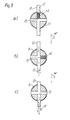
- valve member 11 is formed with intersecting bores.
- the valve member is in position to support resin material 12 in column 13.
- One leg of the valve member 11 is packed with small glass spheres 14 which are carried on a perforated grid 15, such as a wire mesh or gauze, arranged at the end of the leg remote from the column.
- the small glass spheres 14 support the resin material 12 in the column.
- the valve member 11 is rotated through a quarter turn to the position of Figure 3b to allow the resin material to drop out of the column. Rotation of the valve member through a further quarter turn permits discharge of the glass spheres 14 as shown in Figure 3c. Thereafter the valve member can be returned to the Figure 3a position to receive a fresh supply of spheres and the column can be recharged with resin material.
- the grid 15 may be arranged at the end of the leg adjacent the end of the column in the position occupied by the valve member in Figure 3a.
- a column By means of the rotatable valve member, a column can be prepared, unpacked and washed for reuse in a simple and efficient manner.
Landscapes
- Chemical & Material Sciences (AREA)
- Organic Chemistry (AREA)
- Chemical Kinetics & Catalysis (AREA)
- Treatment Of Water By Ion Exchange (AREA)
- Check Valves (AREA)
- Treatment Of Liquids With Adsorbents In General (AREA)
Claims (8)
Applications Claiming Priority (2)
| Application Number | Priority Date | Filing Date | Title |
|---|---|---|---|
| GB8301502 | 1983-01-20 | ||
| GB838301502A GB8301502D0 (en) | 1983-01-20 | 1983-01-20 | Ion exchange columns |
Publications (3)
| Publication Number | Publication Date |
|---|---|
| EP0114739A2 EP0114739A2 (de) | 1984-08-01 |
| EP0114739A3 EP0114739A3 (en) | 1985-05-15 |
| EP0114739B1 true EP0114739B1 (de) | 1988-04-06 |
Family
ID=10536604
Family Applications (1)
| Application Number | Title | Priority Date | Filing Date |
|---|---|---|---|
| EP84300244A Expired EP0114739B1 (de) | 1983-01-20 | 1984-01-16 | Ionen-Austauschsäulen |
Country Status (5)
| Country | Link |
|---|---|
| US (1) | US4540488A (de) |
| EP (1) | EP0114739B1 (de) |
| JP (1) | JPS59139942A (de) |
| DE (1) | DE3470286D1 (de) |
| GB (1) | GB8301502D0 (de) |
Families Citing this family (1)
| Publication number | Priority date | Publication date | Assignee | Title |
|---|---|---|---|---|
| CN101804364B (zh) * | 2010-04-21 | 2012-10-03 | 殷承 | 无法兰的有机玻璃离子交换柱 |
Family Cites Families (2)
| Publication number | Priority date | Publication date | Assignee | Title |
|---|---|---|---|---|
| US1855904A (en) * | 1931-09-16 | 1932-04-26 | Miles P Brown | Screen organization for filter outlets |
| US4120786A (en) * | 1977-03-29 | 1978-10-17 | General Electric Company | Separation of mixed ion exchange resins |
-
1983
- 1983-01-20 GB GB838301502A patent/GB8301502D0/en active Pending
-
1984
- 1984-01-03 US US06/567,515 patent/US4540488A/en not_active Expired - Fee Related
- 1984-01-16 DE DE8484300244T patent/DE3470286D1/de not_active Expired
- 1984-01-16 EP EP84300244A patent/EP0114739B1/de not_active Expired
- 1984-01-20 JP JP59008409A patent/JPS59139942A/ja active Pending
Also Published As
| Publication number | Publication date |
|---|---|
| DE3470286D1 (en) | 1988-05-11 |
| EP0114739A2 (de) | 1984-08-01 |
| US4540488A (en) | 1985-09-10 |
| JPS59139942A (ja) | 1984-08-11 |
| GB8301502D0 (en) | 1983-02-23 |
| EP0114739A3 (en) | 1985-05-15 |
Similar Documents
| Publication | Publication Date | Title |
|---|---|---|
| US4826594A (en) | Portable water conditioning apparatus | |
| US3089508A (en) | Chemical solution tank and means for controlling chemical dosage | |
| JPH01155918A (ja) | フィルター | |
| US4789479A (en) | Packing for chromatography | |
| EP0114739B1 (de) | Ionen-Austauschsäulen | |
| WO2000025883A1 (en) | A new system and its units | |
| US20110272360A1 (en) | Method for operating ion exchange equipment, and ion exchange equipment | |
| EP1345667B1 (de) | Modul zum behandeln von fluiden und verfahren zur herstellung solcher module | |
| US4732333A (en) | Multi-purpose separation apparatus | |
| JP3689109B2 (ja) | カラム配置 | |
| US2203840A (en) | Apparatus for retaining contact masses in tubular elements | |
| EP0106419A2 (de) | Chromatographische Säule | |
| US3143500A (en) | Demineralization column | |
| US4659476A (en) | Method for the treatment of liquids on granular materials | |
| US2420707A (en) | Dehumidifier | |
| US3441503A (en) | Liquid treating apparatus and method | |
| US4416773A (en) | Valve mechanism for multiple distributor fluid treatment system | |
| KR20190002196A (ko) | 재생 화학약품 사용을 줄이기 위한 이온교환 수지 컬럼 장치 및 이의 운전 방법 | |
| US3004668A (en) | Underdrains | |
| Lunn et al. | Removal of biological stains from aqueous solution using a flow-through decontamination procedure | |
| JPH10263529A (ja) | 廃液処理装置 | |
| JPS646912Y2 (de) | ||
| JP2607499Y2 (ja) | 水処理器 | |
| JP2688468B2 (ja) | 粒子分離装置 | |
| US3442624A (en) | Water conditioning system |
Legal Events
| Date | Code | Title | Description |
|---|---|---|---|
| PUAI | Public reference made under article 153(3) epc to a published international application that has entered the european phase |
Free format text: ORIGINAL CODE: 0009012 |
|
| AK | Designated contracting states |
Designated state(s): BE DE FR GB |
|
| PUAL | Search report despatched |
Free format text: ORIGINAL CODE: 0009013 |
|
| AK | Designated contracting states |
Designated state(s): BE DE FR GB |
|
| 17P | Request for examination filed |
Effective date: 19851104 |
|
| 17Q | First examination report despatched |
Effective date: 19860903 |
|
| GRAA | (expected) grant |
Free format text: ORIGINAL CODE: 0009210 |
|
| AK | Designated contracting states |
Kind code of ref document: B1 Designated state(s): BE DE FR GB |
|
| REF | Corresponds to: |
Ref document number: 3470286 Country of ref document: DE Date of ref document: 19880511 |
|
| ET | Fr: translation filed | ||
| PG25 | Lapsed in a contracting state [announced via postgrant information from national office to epo] |
Ref country code: BE Effective date: 19890131 |
|
| PGFP | Annual fee paid to national office [announced via postgrant information from national office to epo] |
Ref country code: GB Payment date: 19890131 Year of fee payment: 6 |
|
| PLBE | No opposition filed within time limit |
Free format text: ORIGINAL CODE: 0009261 |
|
| STAA | Information on the status of an ep patent application or granted ep patent |
Free format text: STATUS: NO OPPOSITION FILED WITHIN TIME LIMIT |
|
| 26N | No opposition filed | ||
| BERE | Be: lapsed |
Owner name: BRITISH NUCLEAR FUELS P.L.C. Effective date: 19890131 |
|
| PG25 | Lapsed in a contracting state [announced via postgrant information from national office to epo] |
Ref country code: FR Free format text: LAPSE BECAUSE OF NON-PAYMENT OF DUE FEES Effective date: 19890929 |
|
| PG25 | Lapsed in a contracting state [announced via postgrant information from national office to epo] |
Ref country code: DE Effective date: 19891003 |
|
| REG | Reference to a national code |
Ref country code: FR Ref legal event code: ST |
|
| PG25 | Lapsed in a contracting state [announced via postgrant information from national office to epo] |
Ref country code: GB Effective date: 19900116 |
|
| GBPC | Gb: european patent ceased through non-payment of renewal fee |