EP0114728A2 - Verfahren und Vorrichtung zum Zurückverwandeln von Scheinleitfähigkeitsmessungen bei Bohrlochinduktionsmessung - Google Patents
Verfahren und Vorrichtung zum Zurückverwandeln von Scheinleitfähigkeitsmessungen bei Bohrlochinduktionsmessung Download PDFInfo
- Publication number
- EP0114728A2 EP0114728A2 EP84300161A EP84300161A EP0114728A2 EP 0114728 A2 EP0114728 A2 EP 0114728A2 EP 84300161 A EP84300161 A EP 84300161A EP 84300161 A EP84300161 A EP 84300161A EP 0114728 A2 EP0114728 A2 EP 0114728A2
- Authority
- EP
- European Patent Office
- Prior art keywords
- conductivity
- formation
- coil system
- coil
- signal
- Prior art date
- Legal status (The legal status is an assumption and is not a legal conclusion. Google has not performed a legal analysis and makes no representation as to the accuracy of the status listed.)
- Withdrawn
Links
- 238000000034 method Methods 0.000 title claims abstract description 44
- 230000006698 induction Effects 0.000 title claims abstract description 33
- 238000005259 measurement Methods 0.000 title claims abstract description 19
- 230000015572 biosynthetic process Effects 0.000 claims abstract description 73
- 238000005316 response function Methods 0.000 claims abstract description 42
- 230000004044 response Effects 0.000 claims abstract description 21
- 230000000694 effects Effects 0.000 claims description 30
- 230000006870 function Effects 0.000 claims description 26
- 230000008859 change Effects 0.000 claims description 7
- 238000011835 investigation Methods 0.000 claims description 6
- 238000006243 chemical reaction Methods 0.000 claims 1
- 230000008878 coupling Effects 0.000 claims 1
- 238000010168 coupling process Methods 0.000 claims 1
- 238000005859 coupling reaction Methods 0.000 claims 1
- 230000004069 differentiation Effects 0.000 claims 1
- 230000001939 inductive effect Effects 0.000 claims 1
- 238000013461 design Methods 0.000 abstract description 5
- 238000005755 formation reaction Methods 0.000 description 53
- 230000007704 transition Effects 0.000 description 10
- 238000010586 diagram Methods 0.000 description 5
- 238000003491 array Methods 0.000 description 3
- 230000008569 process Effects 0.000 description 3
- 230000000644 propagated effect Effects 0.000 description 3
- 230000008901 benefit Effects 0.000 description 2
- 230000001419 dependent effect Effects 0.000 description 2
- 238000001914 filtration Methods 0.000 description 2
- 230000007246 mechanism Effects 0.000 description 2
- 230000009467 reduction Effects 0.000 description 2
- 230000010076 replication Effects 0.000 description 2
- 238000004804 winding Methods 0.000 description 2
- 241000164466 Palaemon adspersus Species 0.000 description 1
- 230000003044 adaptive effect Effects 0.000 description 1
- 238000004458 analytical method Methods 0.000 description 1
- 238000013459 approach Methods 0.000 description 1
- 230000003247 decreasing effect Effects 0.000 description 1
- 230000005672 electromagnetic field Effects 0.000 description 1
- 230000001747 exhibiting effect Effects 0.000 description 1
- 238000000605 extraction Methods 0.000 description 1
- 230000009545 invasion Effects 0.000 description 1
- 239000003208 petroleum Substances 0.000 description 1
- 230000010363 phase shift Effects 0.000 description 1
- 238000005070 sampling Methods 0.000 description 1
- 238000000926 separation method Methods 0.000 description 1
Images

Classifications
-
- G—PHYSICS
- G01—MEASURING; TESTING
- G01V—GEOPHYSICS; GRAVITATIONAL MEASUREMENTS; DETECTING MASSES OR OBJECTS; TAGS
- G01V3/00—Electric or magnetic prospecting or detecting; Measuring magnetic field characteristics of the earth, e.g. declination, deviation
- G01V3/18—Electric or magnetic prospecting or detecting; Measuring magnetic field characteristics of the earth, e.g. declination, deviation specially adapted for well-logging
- G01V3/26—Electric or magnetic prospecting or detecting; Measuring magnetic field characteristics of the earth, e.g. declination, deviation specially adapted for well-logging operating with magnetic or electric fields produced or modified either by the surrounding earth formation or by the detecting device
- G01V3/28—Electric or magnetic prospecting or detecting; Measuring magnetic field characteristics of the earth, e.g. declination, deviation specially adapted for well-logging operating with magnetic or electric fields produced or modified either by the surrounding earth formation or by the detecting device using induction coils
Definitions
- the present invention relates to methods and apparatus for electromagnetic well logging, and embodiments described herein employ a deconvolution technique adaptable to accurate measurement of formation conductivities in a wide variety of formation environments.
- a coil system In induction well logging, a coil system is lowered into a well bore for the purpose of investigating the electrical properties of earth formations adjacent the well bore.
- An electrical property of interest in such investigation is the electrical conductivity of particular portions of the formation.
- induction logging coil systems typically include at least one transmitter coil and one receiver coil, though plural coils or coil arrays are often employed in place of a single transmitter coil or single receiver coil.
- a time varying signal is impressed on the transmitter coil or coil array and a signal is received by the receiver coil or coil array.
- the received signals are a function of the coil system structure and the coil system environment, which, of course, includes formation portions of interest.
- the apparent conductivities measured by the induction coil array differ significantly from those estimated by using the Doll geometric factors particularly in high conductivity formations (i.e., greater than 1 mho per meter) as indicated in Thadani and Hall, Jr., "Propagated Geometric Factors In Induction Logging,” presented at the 22nd Annual SPWLA Symposium, June 1981.
- an induction well logging apparatus comprising: a transmitter and receiver coil system operated so that variation of propagation effects in the formation are negligible, said coil system providing a signal related in value to the apparent conductivity of the formation; and means for operating on said signal with the inverse vertical response function of the coil system to obtain a signal related in value to an approximation of the conductivity of an incremental portion of the formation adjacent the well bore at the depth of investigation.
- the method and apparatus of the invention are used for measuring the conductivity of a general cylindrically symmetric layered earth formation with no invasion, the true conductivity being determined for incremental layers of the earth formation at various depths of interest.
- the embodiments involve running a coil system of essentially arbitrary geometric configuration centered in a well bore, the coil system including at least one receiver coil and at least one transmitter coil; impressing a signal on the transmitter coil; measuring an electrical parameter of the coil system (such as receiver voltage or transmitter frequency) at different depths in the well bore to provide a signal related in value to the apparent conductivity of the formation; operating on a selected plurality of the measured electrical parameters with the inverse vertical response function peculiar to the coil system; and summing the products of the foregoing step over a selected range of depths to produce a signal related in value to the conductivity of the earth formation adjacent the well bore at the depth of interest.
- an electrical parameter of the coil system such as receiver voltage or transmitter frequency
- N measurements of apparent conductivity, o A3 maybe derived from the in phase response of the coil system at N different depth.
- these N measurements may be made through a range of depths approximately centered at a depth of interest z k corresponding to the position of the electric center of the coil system.
- Each of the N apparent conductivity measurements may be operated on by a corresponding one of the N stored values of the inverse vertical response function for the coil system. The products of this operation may be summed to obtain an approximation of the conductivity of an incremental portion of the formation at the depth of interest.
- a vertical response function G for the particular coil system is derived assuming negligible propagation effects, the vertical response function being dictated by the structure of the coil system.
- Values for an inverse vertical response function or deconvolution filter, G -1, are then obtained by means of the ascent algorithm for the case of a single (conductivity) step function. The maximum error in the replication of the single step function is minimized for N selected depths.
- the values of the inverse vertical response function so obtained may be applied to the convolved step function to approximate the original step function.
- Signals obtained from the induction logging coil system, functionally related to the apparent conductivity of the formation may then be converted to a signal functionally related to the actual conductivity of an incremental layer of the formation by employing the inverse vertical response function to deconvolve the coil system signals.
- An apparatus for measuring the conductivity of earth formations may include a coil system having at least one transmitting coil and one receiving coil.
- An oscillator and amplifier may be provided for applying a time varying signal to the transmitting portion of the coil system.
- An electrical characteristic of the coil system such as the receiver voltage, may be detected at a plurality of depths in the well bore to produce an electrical signal related in value to the apparent conductivity at each of the plurality of depths.
- the transmitted signal may be tuned in response to the rate of change of apparent conductivity with an induced variation in frequency of the signal.
- a memory may be provided for storing the values of an inverse vertical response function G v -1 for N locations in a range approximately centered at a reference location z k of the coil system, N being selected according to the degree of depth resolution to be achieved.
- the values for the function Gv -1 may be read from storage and combined with values of the electrical signal to produce an approximation of the true conductivity of an incremental layer of the formation. This process is performed by summing the product of the inverse vertical response function and the electrical signal related in value to the apparent conductivity for each of the N locations.
- the embodiments to be described serve for determining the conductivity of an incremental layer of a formation in a well bore, for a generalized formation having strata of arbitrary thicknesses and conductivities.
- the vertical response of the coil system is maintained essentially constant for all conductivities to facilitate the obtaining of accurate measurements of true conductivity.
- ⁇ (p , z) represents the conductivity of a formation point located at a point with cylindrical coordinates ( p, z).
- the weighting factor gp (p, z) determines the relative contribution of the formation element at (p, z) to the receiver voltage V R and is termed the propagated geometric factor ("pgf"). While not explicitly indicated, the pgf gp ( p, z) depends on the entire formation conductivity distribution, the relative position of the coil system with respect to the point ( p, z), and on the frequency of operation f. If propagation effects are negligible, then the receiver voltage V R may be expressed by the approximation:
- Equation (3) represents a linear depth invariant system, while equation (1) represents a nonlinear depth varying system.
- a solution to the problem may be approached by performing the well logging so that the approximation of equation (3) is satisfied in the formation strata encountered. This may be done by varying the operating frequency of the induction coil system in such a manner that the propagated geometric factors, 9 p ( p, z), are essentially identical to the Doll geometric factors, g D ( p, z). As a result the induction coil system is consistently operated so that equation (3) holds with negligible error, and propagation effects are negligible. Two techniques for accomplishing this frequency variation will now be discussed. These techniques facilitate the use of the linear deconvolution methods, described below, to obtain more accurate values of the true conductivity then can be determined presently using fixed frequency induction logging systems and a multiple point filter such as proposed by Doll.
- the first technique makes use of equation (3) in a homogeneous medium.
- a H is the conductivity of the homogeneous medium.
- a g may be replaced by the value for apparent conductivity, a A..
- the frequency of operation f of the system may be varied in a manner so that the product in constant.
- the receiver voltage V R is held constant at some predetermined value.
- the ratio of the skin depth S v to the skin depth S F for a fixed frequency (F) logging system is given by
- the L/S V ratios improve upon the L/S F ratios at conductivities greater than 10 mmho/M.
- the L/S V ratios are larger than the L/S F ratios; however the absolute magnitudes of the L/S V ratios are still small enough so that propagation effects are negligible.
- K 2 still lower ratios could be achieved. However this would entail operation at lower frequencies and lower constant V R levels.
- Equation (9) indicates that the dynamic range of the frequency measurement would be 40 db as compared to a dynamic range of 80 db for direct measurement of V R as an indication of conductivity. Referring to Table 1 this is confirmed by the range of variation for f which is 1 KHz - 100 KHz or 40 db. This reduction in dynamic range is a distinct advantage of variable frequency operation.
- the pgf gp (p-, z) will approach the Doll gf g D ( p , z) as propagation effects decrease.
- the frequency of operation f is decreased so as to reduce propagation effects.
- the rate of change of the apparent conductivity ⁇ A with respect to frequency is monitored. If this slope is close to zero then gp( p , z) in approximately equal to g D ( p, z) and propagation effects are negligible.
- the slope is compared with a preset threshold e and the frequency reduction from some initial frequency fo (for example, 100 khz) is stopped whenever the slope becomes smaller than this threshold.
- the advantage of this technique is that propagation effects are minimized to a degree determined by the selection of the threshold e, for any arbitrary inhomogeneous formation. However the dynamic range of the apparent conductivity is not reduced by using this technique.
- the actual frequency variation can be accomplished either in analog (feedback) or digital mode.
- a digital (“table look up”) mode may be preferable in certain applications, because the apparatus need only be capable of producing a preselected finite number of frequencies.
- the operating frequency of the system can be changed in a step-wise fashion in response to changes in the apparent conductivity of the formation using a set of preselected cut-off parameters for determining the operating frequency of the system in a particular environment.
- the following operating frequencies could be used with the corresponding conductivity ranges:
- equation (3) collapses to the one dimensional convolution integral
- ⁇ (z) represents the true formation conductivity profile with respect to depth.
- G D (z, z') is the vertical investigation characteristic or response function.
- equation (12) represents a linear depth invariant system sensing the formation parameter a (z) and producing an output signal related in value to the apparent conductivity ⁇ A (z'). This system is readily amenable to linear deconvolution techniques.
- the actual formation conductivity may be modeled as a staircase conductivity profile.
- This 'staircase' conductivity profile a(z) may in turn, be expressed as a weighted linear combination of unit step functions.
- the deconvolution of the weighted linear unit step combination ⁇ (z) may be constructed by using a weighted linear combination of unit step function deconvolutions.
- the deconvolution of a single unit step function u (z) may be accomplished by using minimum Tchebycheff norm filter design techniques.
- GD -1 ( z , z' ) is the desired deconvolution filter for the unit step u(z). Then the signal. u(z) should closely approximate u(z).
- the coefficients of the desired filter GD -1 (z, z') may be determined by minimizing the error between u(z) and its estimate u(z).
- the error criterion E ( T chebycheff norm) is chosen to be
- the coefficients of the deconvolution filter are determined by minimizing E with respect to these coefficients.
- An efficient algorithm to carry out the above minimization currently exists in the literature. This algorithme is known as the Ascent algorithm.
- the deconvolved unit step function u (z) will always have a finite transition region where its value changes from 0 to 1. Also the portions of u (z) away from the transition region will not be exactly flat but will exhibit some ripple.
- a useful aspect of this solution technique is that it allows the specification of the length of the transition region. In particular the shorter the transition region, the larger the ripple in the portions of u (z) outside the transition region. This trade off between transition region length and ripple provides for a large degree of flexibility in the design of the deconvolution filter.
- Embodiments now to be described provide a method and apparatus by which accurate, deconvolved conductivity data can be obtained. More specifically, the apparent conductivity data produced by a system in which variations in the vertical response of the tool due to propagation effects are minimized, can be deconvolved to an essentially arbitrary degree of accuracy dependent on the number of data points selected for each deconvolution computation and upon the computational capacity of the system itself.
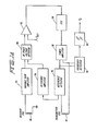
- Well logging devices employing the first frequency variation technique and the deconvolution techniques, discussed above, are shown schematically in Figures 1 and la.
- a generalized downhole coil array is indicated by the numeral 10.
- the coil array 10 may include an arbitrary number of receiver coils and an arbitrary number of transmitter coils.
- U.S. Patent No. 2,582,314 to Doll presents numerous different induction logging coil arrays and their approximate vertical and lateral response functions obtained by ignoring propagation effects.
- a feedback system 12 is provided to stabilize the vertical response of the coil array so that the response is approximately conductivity independent.
- Calculated values for the inverse vertical response function for the coil array 10 in an environment in which propagation effects are negligible, are stored in memory 14. This data is employed by the summation circuit 16 to deconvolve the response of the coil array to provide approximations of the true conductivity of incremental layers of the formation at depths of interest.
- the vertical response of the coil array is maintained approximately constant by the feedback loop 12. That feedback loop detects a voltage across at least one of the receiver coils V R . A component of the receiver voltage in-phase with the time varying transmitter voltage is detected by phase detector 18. The in-phase component of the receiver voltage is then applied to a voltage control oscillator 20, which in turn is used to drive the transmiter coil array. Thus variations in the detected in-phase component of the receiver coil voltage are used to control the operating frequency of the coil array itself.
- a signal proportional to the apparent conductivity of the formation encountered is obtained by first detecting the operating frequency of the coil array with the frequency detector 22. The inverse square of the detected frequency is than calculated by the circuit 24. An output signal of the inverse squaring circuit is proportional to the apparent conductivity at various tool depths, the depths being indicated by the depth indicator 26. Data concerning the depths, the apparent conductivity, and the inverse vertical response function of the particular tool structure are applied to summation circuit 16 which deconvolves the response of the coil array 10 to produce approximations of the true conductivity at various depths of interest. This data may be recorded as a function of depths by the. recorder 28.
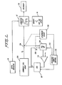
- FIG. la a schematic block diagram is shown for a variable frequency induction logging system employing a coil system having a single receiver coil 40 and a single transmitter coil 42, it being understood that the teachings illustrated in the Figure can be applied to multiple coil systems such as conventional focused systems using 3, 6 or 7 coils.
- the signal received from the receiver coil is applied to a variable gain amplifier 44.
- An output signal of the variable gain amplifier 44 is then applied to an in-phase voltage detector 46.
- the output signal of the in-phase voltage detector 46 is approximately proportional to the portion of the received signal in-phase with the transmitter current. This relationship is insured by detecting the transmitter current by means of the reference detector 48 and reference amplifier 50 which provide a second signal to the voltage detector 46 as a reference so that the in-phase component of the receiver voltage can be selected.
- An output signal of the in-phase voltage detector may be applied to one input terminal of a comparator 52 where the in-phase signal is compared to a reference voltage, V REF .
- the difference signal output of the comparator 52 is applied as a control signal to a voltage control oscillator 54, the voltage control oscillator providing the time varying signal which drives the transmitter coil 42.
- An output signal of the voltage control oscillator 54 is amplified by power amplifier 56 and applied to the transmitter coil 42 thereby completing the feedback loop.
- the operating frequency of the coil system is detected by frequency detector 58 and an output signal therefrom is applied to an inverse squaring circuit 60 which produces a signal related in value to the apparent conductivity of the formation surrounding the receiver and transmitter coils.
- Conductivity data may be obtained from a receiver voltage signal V R , produced by the coil array, which is operated on by deconvolution circuitry similar to that discussed in connection with Figure 1 to obtain a value for the approximate true conductivity of the formation at depths of interest.
- a control system is provided to insure that the system is operated at a frequency at which propagation effects are below the preset threshold e . In other words, propagation effects are minimized to a degree determined by the selection of the threshold value e .
- the downhole coil array may be driven by voltage controlled oscillator 20'.
- the mechanism for determining the frequency of operation of the VCO and coil array will now be discussed.
- the VCO produces a driving signal at frequency f. This signal is applied to the downhole coil array and produces the voltage V R at a receiver coil as an indication of actual formation conductivity.
- a sequencer circuit 202 initiates a tuning sequence during which the VCO is tuned to a frequency which minimizes propagation effects below the predetermined threshold e.
- a switch 204 may be actuated by the sequencer circuit to apply the receiver voltage signal to differentiator circuit 206.
- a switch 208 may be closed by the sequencer circuit to apply the driving signal from the VCO to the differentiator circuit 206.
- the sequencer circuit enables a frequency sample control 210 which varies the frequency of the output signal of the VCO in a predetermined pattern.
- the frequency may be stepped up or down or swept with a triangular wave dithering signal.
- the timing of the frequency variation is communicated to the differentiator circuit 206 as indicated by connection 212.
- the differentiator circuit determines the rate of change of actual formation conductivity (which is approximately proportional to receiver voltage) with frequency.
- a signal related in value to this rate of change may be applied to a first input terminal of a differential amplifier 214 which compares the rate of change to a reference signal related in value to the predetermined threshold e.
- An output difference signal from the differential amplifier 214 may be applied as a tuning signal to the VCO to adjust the operating frequency of the system.
- a sample and hold circuit (not shown) in the VCO may maintain the VCO at the frequency set during the last preceding tuning sequence.
- K TR is a weighting constant for each of the transmitter-receiver pairs
- K eff is a proportionality constant
- g v ij is the geometric factor for each two coil pair
- z K is the center of the longitudinal axis of the coil system
- z k,ij is the center of each coil pair (i j)
- z is the point at which G v is computed.
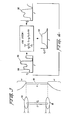
- FIG. 3 the vertical response of a two coil system such as that employed in the apparatus of Figure la will be briefly described.
- a two coil pair including transmitter coil 62 and receiver coil 64, are shown schematically in Figure 3.
- the separation between the two coils is given as dimension L.
- a reference point z k which corresponds to the depth of investigation, is shown centered between the coil pair.
- the plot 66 in Figure 3 is the Doll vertical response of the coil pair, assuming propagation effects are negligible.
- the plot 66 is defined as follows: As discussed above the vertical response function G v for a array of two or more coils including T transmitter coils and R receiver coils can be calculated where propagation effects are negligible using the relationship of equation (16). Such calculated vertical response functions for particular tools, may be used, according to the embodiments described herein, to deconvolve the response of such coil systems, as will be discussed in detail below.
- Measurements obtained from induction logging coil systems are of apparent conductivity ⁇ A (usually given in mho/meter).
- the measured apparent conductivity at any particular depth, assuming cylindrical symmetry about the borehole, is the convolution of the vertical response function of the tool, G v l and true conductivity ⁇ T of the formation at, above, and below the measurement depth.
- the coil system does not normally provide true conductivity measurements for a thin slice of the formation at a depth of interest, but rather, produces an apparent conductivity measurement affected by essentially all of the surrounding formations,. to an extent dictated by the geometry of the coil system.
- the apparent conductivity measured at depth Z K is represented by the convolution integral based on the assumptions given for equation (3) 1 where Z is the vertical axis, generally colinear with the longitudinal axis of the well bore.
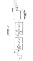
- This convolution is represented diagrammatically in Figure 4 for a two coil system.
- the coil system is located in a formation having the true conductivity shown by plot 100.
- the system produces a plot 102, ⁇ A (Z), which is a distorted replica of ⁇ T (Z).
- This replication is governed by the convolution intregal which, in turn, depends on the vertical response function G v (Z).
- the plot 104 for G v is representative of a conventional two coil system. It should be understood, however, that the methods and apparatus for deconvolution discussed herein are applicable to more complex coil arrays exhibiting more complex G v (Z) plats.
- the true conductivity may be obtained by deconvolving the measured apparent conductivity: where AZ is'the distance between each consecutive pairs of N points selected along the longitudinal axis of the well bore.
- G v - 1 the inverse vertical response function G v - 1 must be found.
- N values of G v -1 are to be determined which deconvolve a single step function convolved by the theoretical vertical response function G v for the particular coil system in use. This process is indicated schematically in Figure 5.
- a hypothetical true conductivity ⁇ T is represented by a single step function 130.
- the step function is convolved with the vertical response function of the tool, assuming negligible propagation effects, to obtain a value of apparent conductivity
- G v -1 being selected to produce a replica 132 of the original single step function 130.
- the accuracy of the approximation will depend, in part, on the number of terms, N, in the summation. -1
- the function G v is found by employing the Ascent algorithm. See E.W. Cheney, Introduction To Approximation Theory, pp.45-51 (McGraw-Hill 1966). The approximation proceeds by iteratively selecting N values for the function G v -1 , by sampling the calculated values of the function ⁇ T at N points to minimize the maximum error between ⁇ T and ⁇ T . Stated in mathematical terms, the maximum error, ⁇ is minimized : or in more compact parallel notation
- a value M may be selected out of the maximum number of the No points. These M points span the transition region of the replica ⁇ T .
- the parameter M is indicated in Figure 5.
- the value M may be viewed as a parameter of depth resolution, having values equal to integral multiples of the distance between adjacent ones of the N points. Generally the smaller the value M, the greater the min max value ⁇ will be and the greater the ripple in ⁇ T will be.
- the Ascent algorithm is applied to the problem in the following steps:
- step 2 The steps 2, 3, 4 and 5 are iterated until the condition of step 4 is satisfied.
- the optimum solution will be reached because there are a finite number of subsets of (N + 1) equations which can be selected out of 20 equations. If, at a given iteration, the value of the deviation
- the geometric parameters of the six coil systems are as follows, the vertically central reference point Z K of the system being assigned the vertical location of inches: wherein T indicates a transmitter coil and R indicates a receiver coil. A negative number of turns indicates a counterclockwise winding and a positive number of turns indicates a clockwise winding. The plane of each of the coils is perpendicular to the Z axis and the radii of the coils are equal.
Landscapes
- Physics & Mathematics (AREA)
- Engineering & Computer Science (AREA)
- Remote Sensing (AREA)
- Life Sciences & Earth Sciences (AREA)
- Electromagnetism (AREA)
- Environmental & Geological Engineering (AREA)
- Geology (AREA)
- General Life Sciences & Earth Sciences (AREA)
- General Physics & Mathematics (AREA)
- Geophysics (AREA)
- Geophysics And Detection Of Objects (AREA)
- Investigating Or Analyzing Materials By The Use Of Magnetic Means (AREA)
Applications Claiming Priority (2)
| Application Number | Priority Date | Filing Date | Title |
|---|---|---|---|
| US457150 | 1983-01-11 | ||
| US06/457,150 US4604581A (en) | 1983-01-11 | 1983-01-11 | Method and apparatus for deconvolving apparent conductivity measurements in induction well logging |
Publications (2)
| Publication Number | Publication Date |
|---|---|
| EP0114728A2 true EP0114728A2 (de) | 1984-08-01 |
| EP0114728A3 EP0114728A3 (de) | 1986-05-14 |
Family
ID=23815641
Family Applications (1)
| Application Number | Title | Priority Date | Filing Date |
|---|---|---|---|
| EP84300161A Withdrawn EP0114728A3 (de) | 1983-01-11 | 1984-01-11 | Verfahren und Vorrichtung zum Zurückverwandeln von Scheinleitfähigkeitsmessungen bei Bohrlochinduktionsmessung |
Country Status (3)
| Country | Link |
|---|---|
| US (1) | US4604581A (de) |
| EP (1) | EP0114728A3 (de) |
| CA (1) | CA1218412A (de) |
Cited By (6)
| Publication number | Priority date | Publication date | Assignee | Title |
|---|---|---|---|---|
| EP0490716A3 (en) * | 1990-11-13 | 1993-05-12 | Schlumberger Limited | Method and apparatus for correcting an induction log for dip effect and producing an output record medium reflecting the correction |
| GB2317016A (en) * | 1996-03-22 | 1998-03-11 | Western Atlas Int Inc | Electromagnetic induction well logging instruments |
| WO2009126888A3 (en) * | 2008-04-10 | 2010-03-04 | Services Petroliers Schlumberger | Method for characterizing a geological formation traversed by a borehole |
| RU2432587C2 (ru) * | 2006-07-26 | 2011-10-27 | Шлюмбергер Текнолоджи Бв | Способ анализа данных с общими и различающимися свойствами |
| US8311788B2 (en) | 2009-07-01 | 2012-11-13 | Schlumberger Technology Corporation | Method to quantify discrete pore shapes, volumes, and surface areas using confocal profilometry |
| US8725477B2 (en) | 2008-04-10 | 2014-05-13 | Schlumberger Technology Corporation | Method to generate numerical pseudocores using borehole images, digital rock samples, and multi-point statistics |
Families Citing this family (16)
| Publication number | Priority date | Publication date | Assignee | Title |
|---|---|---|---|---|
| US4737719A (en) * | 1986-05-21 | 1988-04-12 | Halliburton Company | Coherent detection system for use in induction well logging apparatus |
| US4958286A (en) * | 1988-06-27 | 1990-09-18 | Western Atlas International, Inc. | Time-variant filter coefficients |
| US4949236A (en) * | 1988-08-08 | 1990-08-14 | United States As Represented By The Secretary Of The Air Force | Smart controller |
| US4958073A (en) * | 1988-12-08 | 1990-09-18 | Schlumberger Technology Corporation | Apparatus for fine spatial resolution measurments of earth formations |
| US5210691A (en) * | 1990-05-08 | 1993-05-11 | Schlumberger Technology Corporation | Method and apparatus for producing a more accurate resistivity log from data recorded by an induction sonde in a borehole |
| DE69217816D1 (de) * | 1991-10-21 | 1997-04-10 | Schlumberger Technology Bv | Verfahren und Gerät zum Feststellen und Quantifizieren von kohlwasserstoffenthaltende geschichtete Behälter in einer Verarbeitungsstation |
| US5721491A (en) * | 1994-12-05 | 1998-02-24 | Shell Oil Company | Determining electrical conductivity of an earth layer |
| US6891376B2 (en) * | 2003-07-01 | 2005-05-10 | Kjt Enterprises, Inc. | Method for attenuating conductive sonde mandrel effects in an electromagnetic induction well logging apparatus |
| US7269514B2 (en) * | 2004-05-11 | 2007-09-11 | Halliburton Energy Services, Inc | System and method for correcting induction logging device measurements by alternately estimating geometry and conductivity parameters |
| WO2013019529A2 (en) * | 2011-07-29 | 2013-02-07 | Shell Oil Company | Method for increasing broadside sensitivity in seismic sensing system |
| US20130066559A1 (en) * | 2011-09-12 | 2013-03-14 | Baker Hughes Incorporated | Interpreting borehole transient electromagnetic data using two thin-sheet conductors |
| CN104060986B (zh) * | 2014-06-13 | 2017-01-18 | 中国科学院电工研究所 | 一种多频阵列电测井谐振式发射系统 |
| US10061050B2 (en) * | 2016-08-08 | 2018-08-28 | Gowell International, Llc | Fractal magnetic sensor array using mega matrix decomposition method for downhole application |
| DE102016122800A1 (de) * | 2016-11-25 | 2018-05-30 | Krohne Messtechnik Gmbh | Verfahren zum Betreiben eines induktiven Leitfähigkeitsmessgeräts und diesbezügliches induktives Leitfähigkeitsmessgerät |
| CN111188611B (zh) * | 2018-11-15 | 2023-05-05 | 天津大学青岛海洋技术研究院 | 一种套管井反褶积电阻率处理方法 |
| CN112904433B (zh) * | 2021-01-27 | 2023-03-17 | 天津大学 | 瞬变电磁对称结构的过套管电阻率测井方法 |
Family Cites Families (16)
| Publication number | Priority date | Publication date | Assignee | Title |
|---|---|---|---|---|
| NL294973A (de) * | 1946-06-11 | |||
| US2582314A (en) * | 1949-06-15 | 1952-01-15 | Schlumberger Well Surv Corp | Electromagnetic well logging system |
| NL250643A (de) * | 1959-04-17 | |||
| US3119061A (en) * | 1960-01-21 | 1964-01-21 | Schlumberger Well Surv Corp | Methods and apparatus for investigating earth formations which minimize the influence of electrical skin effect |
| US3147429A (en) * | 1960-02-08 | 1964-09-01 | Schlumberger Well Surv Corp | Induction method and apparatus for investigating earth formation utilizing two quadrature phase components of a detected signal |
| US3312933A (en) * | 1964-04-23 | 1967-04-04 | Mobil Oil Corp | Time variant inverse filter |
| US3403327A (en) * | 1965-09-08 | 1968-09-24 | Schlumberger Technology Corp | Methods and apparatus for processing well logging measurements using time domain computation to obtain the reciprocal function of the measurements |
| US3706025A (en) * | 1969-12-29 | 1972-12-12 | Schlumberger Technology Corp | Induction logging methods and apparatus using more than one phase component of the received signal |
| US4276599A (en) * | 1972-07-31 | 1981-06-30 | Schlumberger Technology Corporation | Method of processing well logging data |
| US4357660A (en) * | 1973-05-01 | 1982-11-02 | Schlumberger Technology Corporation | Formation dip and azimuth processing technique |
| US4302722A (en) * | 1979-06-15 | 1981-11-24 | Schlumberger Technology Corporation | Induction logging utilizing resistive and reactive induced signal components to determine conductivity and coefficient of anisotropy |
| US4334271A (en) * | 1980-02-25 | 1982-06-08 | Schlumberger Technology Corporation | Well logging method and system |
| US4414656A (en) * | 1980-04-15 | 1983-11-08 | Schlumberger Technology Corporation | Well logging system for mapping structural and sedimentary dips of underground earth formations |
| GR75678B (de) * | 1981-06-08 | 1984-08-02 | Schlumberger Ltd | |
| US4471436A (en) * | 1982-01-12 | 1984-09-11 | Schlumberger Technology Corporation | Phasor processing of induction logs including shoulder and skin effect correction |
| US4467425A (en) * | 1982-01-12 | 1984-08-21 | Schlumberger Technology Corporation | Deconvolution filter for induction log processing |
-
1983
- 1983-01-11 US US06/457,150 patent/US4604581A/en not_active Expired - Fee Related
-
1984
- 1984-01-10 CA CA000445004A patent/CA1218412A/en not_active Expired
- 1984-01-11 EP EP84300161A patent/EP0114728A3/de not_active Withdrawn
Cited By (8)
| Publication number | Priority date | Publication date | Assignee | Title |
|---|---|---|---|---|
| EP0490716A3 (en) * | 1990-11-13 | 1993-05-12 | Schlumberger Limited | Method and apparatus for correcting an induction log for dip effect and producing an output record medium reflecting the correction |
| GB2317016A (en) * | 1996-03-22 | 1998-03-11 | Western Atlas Int Inc | Electromagnetic induction well logging instruments |
| GB2317016B (en) * | 1996-03-22 | 2000-10-04 | Western Atlas Int Inc | Electromagnetic induction well logging instruments |
| RU2432587C2 (ru) * | 2006-07-26 | 2011-10-27 | Шлюмбергер Текнолоджи Бв | Способ анализа данных с общими и различающимися свойствами |
| WO2009126888A3 (en) * | 2008-04-10 | 2010-03-04 | Services Petroliers Schlumberger | Method for characterizing a geological formation traversed by a borehole |
| RU2440591C2 (ru) * | 2008-04-10 | 2012-01-20 | Шлюмбергер Текнолоджи Б.В. | Способ получения характеристик геологической формации, пересекаемой скважиной |
| US8725477B2 (en) | 2008-04-10 | 2014-05-13 | Schlumberger Technology Corporation | Method to generate numerical pseudocores using borehole images, digital rock samples, and multi-point statistics |
| US8311788B2 (en) | 2009-07-01 | 2012-11-13 | Schlumberger Technology Corporation | Method to quantify discrete pore shapes, volumes, and surface areas using confocal profilometry |
Also Published As
| Publication number | Publication date |
|---|---|
| US4604581A (en) | 1986-08-05 |
| CA1218412A (en) | 1987-02-24 |
| EP0114728A3 (de) | 1986-05-14 |
Similar Documents
| Publication | Publication Date | Title |
|---|---|---|
| EP0114728A2 (de) | Verfahren und Vorrichtung zum Zurückverwandeln von Scheinleitfähigkeitsmessungen bei Bohrlochinduktionsmessung | |
| EP0115913A1 (de) | Methode und Gerät zur Messung des Bohrprofiles mittels Induktion bei variabler Frequenz | |
| CA2384833C (en) | An electromagnetic induction method and apparatus for the measurement of the electrical resistivity of geologic formations surrounding boreholes cased with a conductive liner | |
| EP0105801B1 (de) | Verwendung der transversalen magnetischen Komponente in einem Bohrlochmessgerät | |
| US6466872B1 (en) | Method for determination of apparent resistivities of anisotropic reservoirs | |
| EP0366719B1 (de) | Pulsinduktionsbohrlochsonde mit erweitertem messbereich sowie deren anwendung | |
| CA2140857C (en) | Well logging method and apparatus involving electromagnetic wave propagation providing variable depth of investigation by combining phase angle and amplitude attenuation | |
| US5884227A (en) | Method for interpreting induction logs in high resistivity contrast earth formations | |
| EP0490716B1 (de) | Verfahren und Gerät zum Korrigieren des Neigungseffekts in Bohrlochinduktionsmessungen und Herstellung einer, die Korrektion wiedergebende, Aufzeichnung | |
| US4278941A (en) | High frequency induction log for determining resistivity and dielectric constant of the earth | |
| NL9200626A (nl) | Werkwijze voor het genereren van gecorrigeerde logs met betrekking tot de soortelijke weerstand van een bodemformatie. | |
| US7567869B2 (en) | Induction tool for detail evaluation of near borehole zone | |
| CA1199681A (en) | Deconvolution filter for induction log processing | |
| US5698982A (en) | Method and system for skin effect correction in a multiple transmit frequency induction logging system | |
| EP0084001B1 (de) | Induktions-Bohrlochmesstechnik | |
| US7714585B2 (en) | Multi-frequency cancellation of dielectric effect | |
| US5146167A (en) | Method and apparatus for determining the conductivity of subsurface earth formations by filtering and summing in-phase and quadrature conductivity signals with correction values | |
| EP1234194A1 (de) | Neues verfahren zur verbesserung der vertikalen auflösung einer zeitlichen zerfallsmessung mit progressiver modellierungsdekonvolution von zeitlichen zerfallspektren | |
| US6611762B1 (en) | Method for determining parameters of earth formations surrounding a well bore | |
| EP0665447A2 (de) | Eliminierungsverfahren von elektromagnetischen Kopplungseffekte in einem Empfangerpaar | |
| GB2135461A (en) | Method and means for interferometric high frequency induction logging | |
| US6449561B1 (en) | Induction logging | |
| US4958286A (en) | Time-variant filter coefficients | |
| US20250284021A1 (en) | Maintaining optimal frequency for nmr formation evaluation using multiple sensitive volumes |
Legal Events
| Date | Code | Title | Description |
|---|---|---|---|
| PUAI | Public reference made under article 153(3) epc to a published international application that has entered the european phase |
Free format text: ORIGINAL CODE: 0009012 |
|
| AK | Designated contracting states |
Designated state(s): AT DE FR GB IT NL |
|
| PUAL | Search report despatched |
Free format text: ORIGINAL CODE: 0009013 |
|
| AK | Designated contracting states |
Kind code of ref document: A3 Designated state(s): AT DE FR GB IT NL |
|
| STAA | Information on the status of an ep patent application or granted ep patent |
Free format text: STATUS: THE APPLICATION IS DEEMED TO BE WITHDRAWN |
|
| 18D | Application deemed to be withdrawn |
Effective date: 19860801 |
|
| RIN1 | Information on inventor provided before grant (corrected) |
Inventor name: THADANI, SURESH GULABRAI Inventor name: MERCHANT, GULAMABBAS ABDULHUSEIN |