EP0114052B1 - Tank-type fast breeder reactor - Google Patents
Tank-type fast breeder reactor Download PDFInfo
- Publication number
- EP0114052B1 EP0114052B1 EP84100131A EP84100131A EP0114052B1 EP 0114052 B1 EP0114052 B1 EP 0114052B1 EP 84100131 A EP84100131 A EP 84100131A EP 84100131 A EP84100131 A EP 84100131A EP 0114052 B1 EP0114052 B1 EP 0114052B1
- Authority
- EP
- European Patent Office
- Prior art keywords
- sodium
- nuclear reactor
- fast breeder
- barrier member
- intermediate heat
- Prior art date
- Legal status (The legal status is an assumption and is not a legal conclusion. Google has not performed a legal analysis and makes no representation as to the accuracy of the status listed.)
- Expired
Links
- DGAQECJNVWCQMB-PUAWFVPOSA-M Ilexoside XXIX Chemical compound C[C@@H]1CC[C@@]2(CC[C@@]3(C(=CC[C@H]4[C@]3(CC[C@@H]5[C@@]4(CC[C@@H](C5(C)C)OS(=O)(=O)[O-])C)C)[C@@H]2[C@]1(C)O)C)C(=O)O[C@H]6[C@@H]([C@H]([C@@H]([C@H](O6)CO)O)O)O.[Na+] DGAQECJNVWCQMB-PUAWFVPOSA-M 0.000 claims description 73
- 229910052708 sodium Inorganic materials 0.000 claims description 73
- 239000011734 sodium Substances 0.000 claims description 73
- 230000004888 barrier function Effects 0.000 claims description 29
- 239000002826 coolant Substances 0.000 claims description 7
- 239000007788 liquid Substances 0.000 claims description 4
- 238000004364 calculation method Methods 0.000 description 12
- 238000013517 stratification Methods 0.000 description 12
- 230000000694 effects Effects 0.000 description 6
- 230000035939 shock Effects 0.000 description 5
- 239000000446 fuel Substances 0.000 description 4
- 230000008646 thermal stress Effects 0.000 description 4
- 230000005540 biological transmission Effects 0.000 description 3
- 230000010355 oscillation Effects 0.000 description 3
- 239000013598 vector Substances 0.000 description 3
- 238000004134 energy conservation Methods 0.000 description 2
- 238000012986 modification Methods 0.000 description 2
- 230000004048 modification Effects 0.000 description 2
- 230000001133 acceleration Effects 0.000 description 1
- 238000013019 agitation Methods 0.000 description 1
- 238000004458 analytical method Methods 0.000 description 1
- 230000001419 dependent effect Effects 0.000 description 1
- 230000001627 detrimental effect Effects 0.000 description 1
- 230000009365 direct transmission Effects 0.000 description 1
- 239000012530 fluid Substances 0.000 description 1
- 230000005484 gravity Effects 0.000 description 1
- 230000001771 impaired effect Effects 0.000 description 1
- 238000004519 manufacturing process Methods 0.000 description 1
- 238000000034 method Methods 0.000 description 1
- 230000007704 transition Effects 0.000 description 1
Images


Classifications
-
- G—PHYSICS
- G21—NUCLEAR PHYSICS; NUCLEAR ENGINEERING
- G21C—NUCLEAR REACTORS
- G21C1/00—Reactor types
- G21C1/02—Fast fission reactors, i.e. reactors not using a moderator ; Metal cooled reactors; Fast breeders
- G21C1/03—Fast fission reactors, i.e. reactors not using a moderator ; Metal cooled reactors; Fast breeders cooled by a coolant not essentially pressurised, e.g. pool-type reactors
-
- Y—GENERAL TAGGING OF NEW TECHNOLOGICAL DEVELOPMENTS; GENERAL TAGGING OF CROSS-SECTIONAL TECHNOLOGIES SPANNING OVER SEVERAL SECTIONS OF THE IPC; TECHNICAL SUBJECTS COVERED BY FORMER USPC CROSS-REFERENCE ART COLLECTIONS [XRACs] AND DIGESTS
- Y02—TECHNOLOGIES OR APPLICATIONS FOR MITIGATION OR ADAPTATION AGAINST CLIMATE CHANGE
- Y02E—REDUCTION OF GREENHOUSE GAS [GHG] EMISSIONS, RELATED TO ENERGY GENERATION, TRANSMISSION OR DISTRIBUTION
- Y02E30/00—Energy generation of nuclear origin
- Y02E30/30—Nuclear fission reactors
Definitions
- This invention relates to a tank-type integrated fast breeder nuclear reactor of the kind as referred to in the precharacterizing portion of patent claim 1.
- a fast breeder reactor is known from R. Carle, J. Br. Nucl. Energy Soc., 1975, 14 July, No. 3, pp 183-190.
- a plurality of intermediate heat exchangers and primary side main circulating pumps are installed within the main container of the reactor in addition to a core and a superstructure for the core.
- the main reactor container also contains a heat-shielding wall which separates the high-temperature primary sodium flowing from the core and the low-temperature sodium from the intermediate heat exchangers.
- FIG. 5 of said report shows a tank-type fast breeder reactor having intermediate heat exchangers within a nuclear reactor container and utilizing sodium as a coolantforthe reactor core and having a heat-shielding structural member for separating a hot plenum and a cold plenum of the nuclear reactor container and wherein a coolant-guiding cylinder surrounds each intermediate heat exchanger.
- thermal striping In the manufacture of such a reactor container.
- One of them is related to oscillations in the sodium temperature (referred to as "thermal striping” hereinafter) in the hot plenum which constitutes a flow path for the primary sodium flowing from the core.
- This thermal striping has an amplitude of several tens of degrees C, and a frequency of about 1 Hz.
- thermal striping occurs at fluid interfaces caused by this temperature difference.
- the high temperature of the primary sodium from the core drops, and this causes a change in density of the primary sodium.
- the so-called temperature stratification phenomenon occurs in which high-temperature low-density sodium stays in the top of the hot plenum and, hence, thermal striping occurs at the interface between the high- and low-temperature sodium layers generated.
- thermal striping is generated in the hot plenum, structural members within the hot plenum such as the core superstructure, the intermediate exchangers, and the primary main circulation pumps, are subjected to repeated temperature fluctuations, so that the integrity of individual structural members will be impaired by the resultant thermal fatigue.
- the occurrence of this temperature stratification leads to the disadvantage that since high-temperature sodium stays within the top part of the hot plenum, the volume of it can mix with the sodium flowing from the core into the hot plenum is reduced.
- the stratification interface accompanying the thermal striping is transmitted to the intermediate heat exchangers since the temperature variations at the core outlet are not moderated sufficiently in the hot plenum, and, consequently, this increases the thermal fatigue on the structural members of each intermediate heat exchanger.
- Another object of the present invention is to provide a tank-type fast breeder which can prevent temperature stratification generated in the hot plenum by the buoyancy of low-density sodium during transitional operation of the plant, e.g., when the reactor is scrammed.
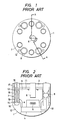
- FIGs. 1 and 2 show a principal part of a well-known tank-type integrated fast breeder nuclear reactor to which the present invention is applied.
- a main container 1 houses a roof slab 2 for isolating the interior of the reactor from the exterior, structural support members, a plurality of intermediate heat exchangers 7, a plurality of primary main circulation pumps 8, and a core 5.
- the core 5 is supported by a core-supporting structural member 3.
- a core superstructure 6 which comprises control rods which control the output of the reactor, the detectors which measure the temperature at the core outlet and the flow rate.
- a hot plenum 9 containing high-temperature sodium flowing from the core 5 is separated by a heat-shielding structural member 4 from a cold plenum 10 containing low-temperature sodium from the intermediate heat exchangers 7.
- the primary sodium flowing from the core 5 first rises through an annular portion defined by the intermediate heat exchanger 7 and a primary sodium guiding cylinder 18, enters the primary sodium inlet ports 13 and then flows into a group of heat transfer tubes 19. It descends while imparting heat to secondary sodium flowing in a closed path, a portion of which is outside of the main container.
- the primary sodium passes through the heat transfer tubes and then flows from primary sodium output ports 14 into the cold plenum 10.
- the primary sodium in the cold plenum is sent to the core 5 by the primary main circulation pumps 8, is heated in the core, and then flows into the hot plenum 9 again.
- the secondary sodium after flowing down through descending tube 15 in the intermediate heat exchanger 7 is distributed to a plurality of heat transfer tubes in a secondary-side lower plenum 16.
- the secondary sodium distributed to each of the heat transfer tubes rises therethrough while receiving heat from the primary sodium, flows together again in a secondary side upper plenum 17, and is then supplied to a steam generator system forming a part of the closed path through a secondary-side outlet nozzle.
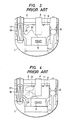
- Fig. 3 shows the flow of primary sodium in the hot plenum 9 during normal operation of the reactor. More specifically, since there is a difference in temperature between the sodium flowing from the core fuel assembly and that from the blanket fuel assembly, high-temperature sub-currents 21 occur within the primary sodium in the top of the hot plenum, and thermal striping is generated at the interfaces where the sub-currents 21 mix with main currents 20 within the primary sodium.
- Fig. 4 shows the flow of primary sodium in the hot plenum 9 during a transitional operation of the reactor.
- a so-called temperature stratification occurs such that high-temperature sodium 21 remains in the top part of the hot plenum because of its buoyancy due to its low density, and low-temperature sodium collected in the lower part thereof.
- thermal striping is generated at the temperature stratification interface where the high-and low-temperature sodium are in contact with each other. If this thermal striping is transmitted to the intermediate heat exchangers 7 by the main currents 20, the structural members of the intermediate heat exchangers are subjected to repeated temperature fluctuations, and this causes thermal fatigue of the structural members.
- a barrier 24 is provided to prevent any thermal striping generated in the primary sodium within the hot plenum 9 described being transmitted to the intermediate heat exchangers 7 directly by the main currents 20.
- a barrier 24 is arranged about each of the intermediate heat exchangers 7.
- the barrier 24 is formed of a cylinder of a larger diameter than that of a primary sodium guiding cylinder 18, its lower end is in contact with the heat-shielding structural member 4, and its upper end is positioned slightly above the lower end of the primary sodium guiding cylinder 18.
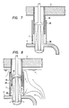
- Fig. 6 shows the flow of the sodium in the hot plenum when the barrier 24 shown in Fig. 5 is provided.
- the amplitude of temperature oscillations within the primary sodium is 100°C (500°C - 400°C) in the region A, but that amplitude becomes about 10°C in the region B where the currents within the primary sodium mix with each other.
- the primary sodium passes through the annular portion around the primary guiding cylinder 18 after leaving the region B, flows into the intermediate heat exchanger 7 through the upper openings (primary sodium inlet ports) 13, and then is discharged below the heat-shielding structural member 4 through the lower openings (primary sodium outlet ports) 1.4.
- the illustrated embodiment controls the primary sodium flow path and serves for any current of sodium with large-amplitude temperature oscillations from directly reaching the intermediate heat exchanger 7. It, thus, becomes possible to prevent any thermal striping generated within the hot plenum from being transmitted directly to the intermediate heat exchangers. Further, since the provision of the barrier 24 is intended to provide the effect that the sodium within the plenum is agitated. It is also possible to prevent a temperature stratification within the hot plenum during transitional operation of the plant, e.g., when the reactor is scrammed, which provides the effect of moderating thermal shock and thermal stress imparted to the structural members of the reactor as a result of temperature stratification. Incidentally, when the gap between the primary sodium and guiding cylinder 18 and the barrier 25 in Fig. 5 is large, the upper end of the barrier 24 should preferably be positioned slightly higher than the lower end of the primary sodium guiding cylinder 18.
- a dam barrier 25 is formed of a cylinder of a larger diameter than that of the primary sodium guiding cylinder 18, its lower end is in contact with the heat-shielding structural member 4, and a plurality of ports 26 are formed around the periphery of its lower end.
- Fig. 8 shows the flow of sodium within the hot plenum when the barrier 25 is provided.
- the primary sodium flows over the upper end of the dam 25 and through the ports 26, sodium from the top of the plenum mixes with that from its bottom and then the mixed sodium passes through the annulus portion around the primary sodium guiding cylinder 18.
- the sodium passing through the pots 26 does not flow into the interior of the barrier 25 with the same flow conditions it has within the plenum, but is first caused to flow in the same direction by the several ports 26, so that thermal striping can be prevented from being transmitted directly to the intermediate heat exchangers 7.
- the agitation effect of the sodium within the barrier 25 is large, it is also possible to prevent the generation of a temperature stratification within the hot plenum during the transitional operation of the plant and the even more significant effect is provided that thermal shock and thermal stress imparted to the internal structure members of the reactor as a result of that phenomenon are moderated.
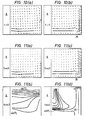
- This calculation model was based on the assumptions that the flow paths within the hot plenum can be approximated by a tow-dimensional, axially symmetric model, and that the inlet portion of an intermediate heat exchanger is formed of an opening provided in the reactor wall.
- the calculation was based on a finite differential method by solving the following approximated equations of mass, momentum, and energy conservation assuming the case of a non-compressive liquid, because the sodium used as the coolant is a single-phase liquid.
- Fig. 10 shows the results of calculations when flow rate vectors representing normal operation were applied to calculation models of the prior-art structure (without barrier), and that of the present invention (the embodiment of Fig. 7).
- the sodium can be seen to flow into the intermediate heat exchanger from the upper and lower ends of the cylinder (barrier 25), preventing the transmission of thermal striping. Therefore, sodium from the top and bottom of the plenum is mixed before it enters the intermediate heat exchanger, and this makes it possible to prevent thermal striping generated in the plenum being transmitted directly to the intermediate heat exchanger.
- Figs. 11 (a) and 11(b) show the results of calculations on the flow rate vectors and temperature profile within the hot plenum during a scram of a reactor with the prior-art structure (without barrier), respectively.
- Figs. 11 (c) and 11 (d) show the results of calculations on the flow rate vectors and temperature profile within the hot plenum during a scram of a reactor with the present invention (Fig. 7), respectively.
- FIG. 12 Another embodiment of the present invention is illustrated in Fig. 12. As shown, a barrier 27 whose lower end is separated from the heat-shielding structural member 4 by a gap 28 and whose upper end is higher than the lower end of the guide member 18 is provided. Further, another cylindrical member or barrier 29 of a larger diameter than that of the barrier 27 is arranged to surround it in such a manner that the lower end of the cylindrical member is in contact with the heat-shielding structural member 4, and its upper end is positioned above the lower end of the barrier 27. In this case, it is also possible to prevent a thermal striping from being transmitted directly to the intermediate heat exchangers.
Landscapes
- Physics & Mathematics (AREA)
- Engineering & Computer Science (AREA)
- Plasma & Fusion (AREA)
- General Engineering & Computer Science (AREA)
- High Energy & Nuclear Physics (AREA)
- Heat-Exchange Devices With Radiators And Conduit Assemblies (AREA)
- Electrical Discharge Machining, Electrochemical Machining, And Combined Machining (AREA)
- Other Investigation Or Analysis Of Materials By Electrical Means (AREA)
Applications Claiming Priority (2)
| Application Number | Priority Date | Filing Date | Title |
|---|---|---|---|
| JP2184/83 | 1983-01-12 | ||
| JP58002184A JPS59126993A (ja) | 1983-01-12 | 1983-01-12 | タンク型高速増殖炉 |
Publications (3)
| Publication Number | Publication Date |
|---|---|
| EP0114052A2 EP0114052A2 (en) | 1984-07-25 |
| EP0114052A3 EP0114052A3 (en) | 1985-06-12 |
| EP0114052B1 true EP0114052B1 (en) | 1988-09-21 |
Family
ID=11522272
Family Applications (1)
| Application Number | Title | Priority Date | Filing Date |
|---|---|---|---|
| EP84100131A Expired EP0114052B1 (en) | 1983-01-12 | 1984-01-09 | Tank-type fast breeder reactor |
Country Status (3)
| Country | Link |
|---|---|
| EP (1) | EP0114052B1 (enExample) |
| JP (1) | JPS59126993A (enExample) |
| DE (1) | DE3474227D1 (enExample) |
Family Cites Families (2)
| Publication number | Priority date | Publication date | Assignee | Title |
|---|---|---|---|---|
| FR2276663A1 (fr) * | 1974-06-25 | 1976-01-23 | Commissariat Energie Atomique | Structure de support pour coeur de reacteur nucleaire a neutrons rapides |
| JPS57194387A (en) * | 1981-05-27 | 1982-11-29 | Hitachi Ltd | Main container of tank type fast reactor |
-
1983
- 1983-01-12 JP JP58002184A patent/JPS59126993A/ja active Granted
-
1984
- 1984-01-09 EP EP84100131A patent/EP0114052B1/en not_active Expired
- 1984-01-09 DE DE8484100131T patent/DE3474227D1/de not_active Expired
Also Published As
| Publication number | Publication date |
|---|---|
| JPH0411835B2 (enExample) | 1992-03-02 |
| JPS59126993A (ja) | 1984-07-21 |
| EP0114052A3 (en) | 1985-06-12 |
| DE3474227D1 (en) | 1988-10-27 |
| EP0114052A2 (en) | 1984-07-25 |
Similar Documents
| Publication | Publication Date | Title |
|---|---|---|
| US3962032A (en) | Fast nuclear reactor | |
| US5112569A (en) | Intrinsic-safety nuclear reactor of the pressurized water type | |
| US3498880A (en) | Liquid cooled nuclear reactor with means for isolating heat exchanger | |
| US3725199A (en) | Nuclear reactor organization and fuel assembly arrangement | |
| Weisman | The current status of theoretically based approaches to the prediction of the critical heat flux in flow boiling | |
| US3321376A (en) | High temperature nuclear reactor | |
| US3296085A (en) | Calandria core for sodium graphite reactor | |
| US3080308A (en) | Simplified sodium graphite reactor system | |
| US4302296A (en) | Apparatus for insulating hot sodium in pool-type nuclear reactors | |
| US4705662A (en) | Fast neutron nuclear reactor with a steam generator integrated into the vessel | |
| EP0114052B1 (en) | Tank-type fast breeder reactor | |
| US4560531A (en) | Device for partitioning off the core of a nuclear reactor | |
| US3211623A (en) | Neutronic reactor and fuel element therefor | |
| US4557891A (en) | Pressurized water reactor flow arrangement | |
| El-Genk et al. | Forced and combined convection of water in rod bundles | |
| GB2208961A (en) | Anti-vibration flux thimble | |
| Ruyer et al. | Using CFD in the frame of safety studies–Some IRSN experiences | |
| JPH1123773A (ja) | 高速増殖炉の炉心冷却構造 | |
| Chauhan et al. | Thermal Hydraulics of Intermediate Heat Exchangers for SFRs | |
| JPH02183198A (ja) | 一次循環ループ水位計付加圧水型原子炉 | |
| De et al. | Prediction of CANDU-6 moderator system response following a large break LOCA using a 3D model | |
| JP3483214B2 (ja) | 液体金属冷却高速炉 | |
| JP3126550B2 (ja) | 原子炉容器壁の冷却機構 | |
| JPH0338558B2 (enExample) | ||
| Bettis et al. | Lead-Cooled Molten Salt Reactors |
Legal Events
| Date | Code | Title | Description |
|---|---|---|---|
| PUAI | Public reference made under article 153(3) epc to a published international application that has entered the european phase |
Free format text: ORIGINAL CODE: 0009012 |
|
| 17P | Request for examination filed |
Effective date: 19840112 |
|
| AK | Designated contracting states |
Designated state(s): DE FR GB |
|
| PUAL | Search report despatched |
Free format text: ORIGINAL CODE: 0009013 |
|
| AK | Designated contracting states |
Designated state(s): DE FR GB |
|
| 17Q | First examination report despatched |
Effective date: 19861120 |
|
| R17C | First examination report despatched (corrected) |
Effective date: 19870507 |
|
| GRAA | (expected) grant |
Free format text: ORIGINAL CODE: 0009210 |
|
| AK | Designated contracting states |
Kind code of ref document: B1 Designated state(s): DE FR GB |
|
| REF | Corresponds to: |
Ref document number: 3474227 Country of ref document: DE Date of ref document: 19881027 |
|
| ET | Fr: translation filed | ||
| PLBE | No opposition filed within time limit |
Free format text: ORIGINAL CODE: 0009261 |
|
| STAA | Information on the status of an ep patent application or granted ep patent |
Free format text: STATUS: NO OPPOSITION FILED WITHIN TIME LIMIT |
|
| 26N | No opposition filed | ||
| PGFP | Annual fee paid to national office [announced via postgrant information from national office to epo] |
Ref country code: GB Payment date: 19961230 Year of fee payment: 14 |
|
| PGFP | Annual fee paid to national office [announced via postgrant information from national office to epo] |
Ref country code: FR Payment date: 19970117 Year of fee payment: 14 |
|
| PGFP | Annual fee paid to national office [announced via postgrant information from national office to epo] |
Ref country code: DE Payment date: 19970327 Year of fee payment: 14 |
|
| PG25 | Lapsed in a contracting state [announced via postgrant information from national office to epo] |
Ref country code: GB Free format text: LAPSE BECAUSE OF NON-PAYMENT OF DUE FEES Effective date: 19980109 |
|
| PG25 | Lapsed in a contracting state [announced via postgrant information from national office to epo] |
Ref country code: FR Free format text: THE PATENT HAS BEEN ANNULLED BY A DECISION OF A NATIONAL AUTHORITY Effective date: 19980131 |
|
| GBPC | Gb: european patent ceased through non-payment of renewal fee |
Effective date: 19980109 |
|
| PG25 | Lapsed in a contracting state [announced via postgrant information from national office to epo] |
Ref country code: DE Free format text: LAPSE BECAUSE OF NON-PAYMENT OF DUE FEES Effective date: 19981001 |
|
| REG | Reference to a national code |
Ref country code: FR Ref legal event code: ST |