EP0113902A2 - Automatisches Bandfilter - Google Patents
Automatisches Bandfilter Download PDFInfo
- Publication number
- EP0113902A2 EP0113902A2 EP83112785A EP83112785A EP0113902A2 EP 0113902 A2 EP0113902 A2 EP 0113902A2 EP 83112785 A EP83112785 A EP 83112785A EP 83112785 A EP83112785 A EP 83112785A EP 0113902 A2 EP0113902 A2 EP 0113902A2
- Authority
- EP
- European Patent Office
- Prior art keywords
- tape
- filter
- head support
- support member
- tape head
- Prior art date
- Legal status (The legal status is an assumption and is not a legal conclusion. Google has not performed a legal analysis and makes no representation as to the accuracy of the status listed.)
- Granted
Links
Images
Classifications
-
- B—PERFORMING OPERATIONS; TRANSPORTING
- B01—PHYSICAL OR CHEMICAL PROCESSES OR APPARATUS IN GENERAL
- B01D—SEPARATION
- B01D29/00—Filters with filtering elements stationary during filtration, e.g. pressure or suction filters, not covered by groups B01D24/00 - B01D27/00; Filtering elements therefor
- B01D29/09—Filters with filtering elements stationary during filtration, e.g. pressure or suction filters, not covered by groups B01D24/00 - B01D27/00; Filtering elements therefor with filtering bands, e.g. movable between filtering operations
Definitions
- the present invention relates to an apparatus for the removal of solids from liquid media, wherein said material is caused to flow through a filter media, such as filter tape.
- a filter media such as filter tape.
- a replaceable cartridge filter such as U.S. Patent 3,495,463 provides a filter cartridge on a support means within a funnel shaped cavity.
- filters such as these tend to absorb organic material and bleed it back into the sample stream over a long period of time. This can mask concentration peaks and make accurate analysis of a liquid sample a considerable problem.
- said filters since said filters do encounter significant bleeding problems, they must be changed frequently.
- Russian Patent 251,242 discloses a tape filter device having a pivoting arm which is operated by a pneumatic system. The pivoting motion of the arm connects the sample liquid to the filter device.
- the filter device is situated such that the filter tape is vertically drawn across its surface. This device hampers the production of a uniform sample of filtered liquid since there is a build-up of solid matter at the bottom portion thereof. The vertical movement of the filter tape as the sample liquid is flowing through it, coupled with this build-up of solid material, prevents this device from providing a fresh filtering surface.
- U.S. Patent No. 3,471,017 discloses that a filter band or ribbon may be passed through inlet and outlet ports in a filtering apparatus across the path of material flow and that an adequate seal may be maintained at the inlet and outlet ports by carefully maintaining a solidified plug of the material within the ports as a sealant. A difference in size between the inlet plug and the outlet plug is relied upon to advance the filter band through the apparatus. To insure a complete seal of the plugs utilized in this apparatus, they must be sufficiently cooled to form a relatively solid mass which tends to bind in the inlet and outlet ports, and this makes filter screen chanqing difficult. If the plugs are formed in a less solid state, undesirable leakage of material occurs.
- this apparatus utilizes high pressures associated with an extrusion process that force the filter band to dimple into the access holes of the back-up or breaker plate supporting the filter band. This makes it extremely difficult to change the position of the filter band.
- This patent is a relatively complicated device, which affords limited filter area, requires frequent changes of the filter media, and has a complicated mechanism to avoid leakage of contaminated liquid around the edges of the filter medium.
- filter device Another type of filter device, the "Fox Filter” Research Disclosure, 13356, (May 1975), has a tapered filter head which is "grooved and shaped" such that a strip of filter tape may be guided across a channel drilled through the side of the filter head. Filtered liquid is induced to flow through the tape into a channel located within the filter head via gravity or a vacuum.
- the filter head is mounted within a weir box havinq an inlet channel and an outlet channel. Liquid sample is fed into the weir box and allowed to overflow through the outlet channel located in the upper portion of the reservoir.
- the tapered configuration of the filter head provides poor sealing around the tape to filter head interface thereby allowing solid waste materials to contaminate the filtered sample.
- the apparatus is designed such that the weir must be drained before the filter can be changed and it must be disassembled for cleaning. Furthermore, the flow pattern through the rectangular weir box causes said weir to fill with solids above the tape head. The filter tape may thereby become clogqed with solid material.
- the present invention provides a simplified apparatus which avoids leakage of contaminated liquid around the edges of the filter media through the unique configuration of the tape head, and provides a fresh filtering surface to avoid buildup of solid material on the filter media.
- the present invention provides a liquid filter medium with a maximum of surface area which enables the filter medium to accommodate a sample of larger volume.
- the unique design of the weir of the present invention prevents the buildup of solid material in the liquid channeling device.
- the present invention provides an apparatus for intermittent or continuous sampling of liquid media.
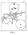
- the present invention is mounted to a panel (1).
- a supply reel (2) supplies filter tape (3) which passes between tape guide rollers (4) and (5) to a tape head support member (6) and around its guide surface (7).
- Types of filter media include: filter paper, non-woven fibrous filters, or any other suitable material.
- the tape head support member (6) is grooved and shaped so that filter tape may be guided across and around its guide surface (7).
- the configuration of the tape head support member (6) enables the filter media to fit across its guide surface (7) in a manner that avoids leakage of the contaminated liquid around the edges of the filter medium.
- the filter media is in contact with the guide surface before it is immersed within the liquid media thus insuring that contaminated liquid does not contact the clean side of the filter tape.
- the filter tape is then passed over tape guide roller (8) and between a tape transport roller and a pressure roller (9) and (10) respectively, to take up reel (11).
- the tape transport roller (9) has teeth which enable it to grip the filter tape.
- Pressure roller (10) holds the tape in contact with tape transport roller (9).
- the tape head support member (6) is secured to a tape head support plate (12) having a ratchet-operated tape transport system, which moves the tape through the guide rollers and around the tape head support member (6) as illustrated above.
- the filter tape is advanced over the guide surface (7) of the tape head support member (6) as the tape head support plate (12) is raised by means of the air actuator (13) or other similar means.
- any driving means such as an electric motor, manual means, etc., may be utilized to drive the tape head support plate (12).
- Fig. 1 illustrates the present invention with the tape head support plate (12) in its upright position.
- the tape head support plate (12) is lowered by means of an air actuator (13)
- the attached tape head support member (6) is lowered into the weir (15).
- spring (14) exerts a force on the tape head support plate (12) thereby raising the attached tape support member (6) out of the weir (15).
- the force exerted by the air actuator (13) causes ratchet wheel (17) to rotate in a clockwise manner, thereby moving ratchet pawls (18) and (19) the appropriate number of notches.
- the air actuator (13) moves tape head support plate (12) downward, thereby lowering tape head support member (6) into the weir (15).
- the shape of the weir (15) enables solids to be carried out by the flow of the liquid media as it is channeled through the weir (15) and into the outlet passages (16), thereby preventing the build up of solid matter.
- an aspirator (21), or other similar device for regulating air pressure Prior to lowering the tape head support member (6) into the weir (15) an aspirator (21), or other similar device for regulating air pressure, begins to lower the pressure within the collecting chamber (22) of the tape head support member (6).
- the filter tape is brought into contact with the tape head support member (6) before it is immersed in the weir (15) and it remains in contact with the tape head (6) until after it exits from the weir (15). This prevents the solids from contacting the clean side of the tape.
- the collecting chamber (22) is maintained at a pressure lower than the pressure outside said chamber.
- the lower pressure within the colleeting ' chamber (22) forces the liquid media to flow through the filtrate passages (23) and into the collecting chamber (22).
- the lower pressure within the collecting chamber (22), in combination with the curvature of the tape head, further insures that the filter tape is securely situated against the guide surface (7) of the tape head support member (6). Additional tension is supplied by tape guide rollers (4) and (5). This additional tension prevents solid material from flowing around the filter tape and into the filtrate passages and contaminating the liquid sample.
- the tape head support member (6) is shaped so as to cause liquid media to flow tangentially across its guide surface (7) when said member (6) is immersed within the weir.
- the tangential flow across the guide surface (7) prevents a buildup of solid organic material on the surface of the filter tape. A fresh filter surface is therefore always insured.
- the apparatus as illustrated in Fig. 1 is utilized when an intermittent sample of liquid wastewater is needed.
- the filtered sample collects within collecting chamber (22), and is then removed via an aspirator (21) out of said chamber (22) to an analyzer.
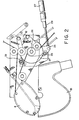
- FIG. 2 An alternate embodiment of this invention, as illustrated in Fig. 2, is a tape filter device as depicted in Fig. 1 without a collecting chamber within the tape head support member (6). Utilizing this embodiment of the invention, a continuous sample of liquid wastewater of larger volume may be achieved. In this instance, the tape head support member (6) is continuously immersed within the weir (15). The tape head support member (6) is only lifted when the filter tape is changed. This provides an uninterrupted flow of contaminated liquid through the weir (15) and permits fresh tape to be installed without interrupting the filtering process.
- This embodiment of the invention has a tape transport drive assembly with a ratchet lever (24) that pivots on the same center as the ratchet wheel (17).
- This lever (24) carries a pawl (25) that rotates the ratchet wheel (17) and its attached tape drive roller (26).
- a back stop pawl (28) on the tape head support plate (12) prevents the reverse rotation of the ratchet wheel (17).
- the ratchet lever (24) is driven by an air cylinder (27) or other suitable driving means, i.e., variable stroke crank electric motor. Any other suitable means for transporting the filter media may be utilized.
- variable stroke crank may be adjusted to move one or more notches on the ratchet wheel (17) per stroke, or a movable stop (29) on the air cylinder rod (27) may be adjusted to vary the number of notches moved on the ratchet wheel (17) per stroke. Additionally, the intervals between the strokes of the air cylinder may be varied by adjusting a timer (not shown) which controls the pulsating air supply to the air-cylinder rod (27).
Landscapes
- Chemical & Material Sciences (AREA)
- Chemical Kinetics & Catalysis (AREA)
- Sampling And Sample Adjustment (AREA)
- Filtration Of Liquid (AREA)
Applications Claiming Priority (2)
| Application Number | Priority Date | Filing Date | Title |
|---|---|---|---|
| US06/451,179 US4427543A (en) | 1982-12-20 | 1982-12-20 | Automatic tape filter |
| US451179 | 1982-12-20 |
Publications (3)
| Publication Number | Publication Date |
|---|---|
| EP0113902A2 true EP0113902A2 (de) | 1984-07-25 |
| EP0113902A3 EP0113902A3 (en) | 1985-05-02 |
| EP0113902B1 EP0113902B1 (de) | 1987-08-12 |
Family
ID=23791124
Family Applications (1)
| Application Number | Title | Priority Date | Filing Date |
|---|---|---|---|
| EP83112785A Expired EP0113902B1 (de) | 1982-12-20 | 1983-12-19 | Automatisches Bandfilter |
Country Status (4)
| Country | Link |
|---|---|
| US (1) | US4427543A (de) |
| EP (1) | EP0113902B1 (de) |
| JP (1) | JPS59115714A (de) |
| DE (1) | DE3372922D1 (de) |
Families Citing this family (1)
| Publication number | Priority date | Publication date | Assignee | Title |
|---|---|---|---|---|
| US6174446B1 (en) | 1999-03-23 | 2001-01-16 | Erik J. Andresen | Vacuum filter apparatus and method for recovering contaminated liquid |
Family Cites Families (9)
| Publication number | Priority date | Publication date | Assignee | Title |
|---|---|---|---|---|
| US2679158A (en) | 1951-01-16 | 1954-05-25 | Research Corp | Double stage sediment tester |
| US2675129A (en) | 1951-05-23 | 1954-04-13 | Sherwin Williams Co | Continuous filter |
| US2795288A (en) | 1956-01-16 | 1957-06-11 | Hirs Gene | Filter apparatus |
| FR1266944A (fr) * | 1960-09-07 | 1961-07-17 | Metal Chlorides Corp | Procédé et appareil pour effectuer des réactions à haute température, notamment pour chlorurer des minerais |
| US3244287A (en) | 1962-12-21 | 1966-04-05 | Coleman Instr Corp | Continuous filtration |
| US3310172A (en) | 1963-02-28 | 1967-03-21 | Manitowoc Engineering Corp | Apparatus for filtering liquid |
| US3332553A (en) * | 1964-10-29 | 1967-07-25 | Barnes Drill Co | Vacuum filter |
| US4054521A (en) | 1972-05-10 | 1977-10-18 | Brunswick Corporation | Indexing mechanism |
| JPS56152715A (en) * | 1980-04-28 | 1981-11-26 | Int Fuirutaazu Corp | Automatic filter device |
-
1982
- 1982-12-20 US US06/451,179 patent/US4427543A/en not_active Expired - Fee Related
-
1983
- 1983-12-19 JP JP58238048A patent/JPS59115714A/ja active Granted
- 1983-12-19 DE DE8383112785T patent/DE3372922D1/de not_active Expired
- 1983-12-19 EP EP83112785A patent/EP0113902B1/de not_active Expired
Also Published As
| Publication number | Publication date |
|---|---|
| US4427543A (en) | 1984-01-24 |
| DE3372922D1 (en) | 1987-09-17 |
| JPS6349526B2 (de) | 1988-10-05 |
| EP0113902B1 (de) | 1987-08-12 |
| EP0113902A3 (en) | 1985-05-02 |
| JPS59115714A (ja) | 1984-07-04 |
Similar Documents
| Publication | Publication Date | Title |
|---|---|---|
| EP0409817B1 (de) | Filterapparat zur Abtrennung von Fest- und Schwebstoffen aus Flüssigkeiten | |
| EP0546308B1 (de) | Filtrationssystem | |
| EP0738531B1 (de) | Drehtrommelvorrichtung zum Trennen von Feststoffpartikeln aus einer Flüssigkeit und Herstellungsverfahren und Vorrichtung hierfür | |
| US4519906A (en) | Apparatus for the separation of magnetic and nonmagnetic solid particles from a liquid | |
| MX9304122A (es) | Mejoras en un filtro de fluido lavable por contracorriente. | |
| US3647082A (en) | Filter press | |
| US4427543A (en) | Automatic tape filter | |
| US5362384A (en) | Multi-cell filter apparatus and turbidity monitor | |
| US3244287A (en) | Continuous filtration | |
| US3305094A (en) | Vaccum filter | |
| US1574557A (en) | Filtering apparatus | |
| HU213988B (en) | Filter for liquids | |
| US1762560A (en) | Method of filtering | |
| CN116619582B (zh) | 一种适用于建筑砖生产的自动切割机 | |
| US4226716A (en) | Rotary filter | |
| CN206561675U (zh) | 丝印机 | |
| US4073631A (en) | Stationary drum filtration device and method | |
| DE3432377C2 (de) | ||
| CN221692999U (zh) | 一种食品加工用过滤装置 | |
| CN118389203B (zh) | 一种物理法山茶籽油精炼设备 | |
| JP3171051B2 (ja) | 試料液のサンプリング装置 | |
| CN221480021U (zh) | 一种湿法冶金溶液杂质去除装置 | |
| SU1262329A1 (ru) | Пробоотборник дл непрерывного отбора фильтрата | |
| DE8910851U1 (de) | Bandfilter | |
| CN120628694A (zh) | 一种高原农业面源水污染检测装置及方法 |
Legal Events
| Date | Code | Title | Description |
|---|---|---|---|
| PUAI | Public reference made under article 153(3) epc to a published international application that has entered the european phase |
Free format text: ORIGINAL CODE: 0009012 |
|
| AK | Designated contracting states |
Designated state(s): DE GB IT NL |
|
| PUAL | Search report despatched |
Free format text: ORIGINAL CODE: 0009013 |
|
| AK | Designated contracting states |
Designated state(s): DE GB IT NL |
|
| 17P | Request for examination filed |
Effective date: 19850701 |
|
| 17Q | First examination report despatched |
Effective date: 19860224 |
|
| GRAA | (expected) grant |
Free format text: ORIGINAL CODE: 0009210 |
|
| AK | Designated contracting states |
Kind code of ref document: B1 Designated state(s): DE GB IT NL |
|
| PG25 | Lapsed in a contracting state [announced via postgrant information from national office to epo] |
Ref country code: NL Effective date: 19870812 Ref country code: IT Free format text: LAPSE BECAUSE OF FAILURE TO SUBMIT A TRANSLATION OF THE DESCRIPTION OR TO PAY THE FEE WITHIN THE PRESCRIBED TIME-LIMIT;WARNING: LAPSES OF ITALIAN PATENTS WITH EFFECTIVE DATE BEFORE 2007 MAY HAVE OCCURRED AT ANY TIME BEFORE 2007. THE CORRECT EFFECTIVE DATE MAY BE DIFFERENT FROM THE ONE RECORDED. Effective date: 19870812 |
|
| REF | Corresponds to: |
Ref document number: 3372922 Country of ref document: DE Date of ref document: 19870917 |
|
| NLV1 | Nl: lapsed or annulled due to failure to fulfill the requirements of art. 29p and 29m of the patents act | ||
| PLBE | No opposition filed within time limit |
Free format text: ORIGINAL CODE: 0009261 |
|
| STAA | Information on the status of an ep patent application or granted ep patent |
Free format text: STATUS: NO OPPOSITION FILED WITHIN TIME LIMIT |
|
| 26N | No opposition filed | ||
| GBPC | Gb: european patent ceased through non-payment of renewal fee | ||
| PG25 | Lapsed in a contracting state [announced via postgrant information from national office to epo] |
Ref country code: DE Effective date: 19880901 |
|
| PG25 | Lapsed in a contracting state [announced via postgrant information from national office to epo] |
Ref country code: GB Free format text: LAPSE BECAUSE OF NON-PAYMENT OF DUE FEES Effective date: 19881122 |