EP0113622B1 - Method and device to propel space craft - Google Patents
Method and device to propel space craft Download PDFInfo
- Publication number
- EP0113622B1 EP0113622B1 EP19830402424 EP83402424A EP0113622B1 EP 0113622 B1 EP0113622 B1 EP 0113622B1 EP 19830402424 EP19830402424 EP 19830402424 EP 83402424 A EP83402424 A EP 83402424A EP 0113622 B1 EP0113622 B1 EP 0113622B1
- Authority
- EP
- European Patent Office
- Prior art keywords
- ergol
- tanks
- tank
- satellite
- upstream
- Prior art date
- Legal status (The legal status is an assumption and is not a legal conclusion. Google has not performed a legal analysis and makes no representation as to the accuracy of the status listed.)
- Expired
Links
- 238000000034 method Methods 0.000 title claims description 8
- 238000011144 upstream manufacturing Methods 0.000 claims description 29
- 230000001133 acceleration Effects 0.000 claims description 16
- 238000002347 injection Methods 0.000 claims description 15
- 239000007924 injection Substances 0.000 claims description 15
- 238000005192 partition Methods 0.000 claims description 12
- 229910052751 metal Inorganic materials 0.000 claims description 6
- 239000002184 metal Substances 0.000 claims description 6
- 238000004891 communication Methods 0.000 claims description 3
- 230000000750 progressive effect Effects 0.000 claims description 3
- 238000004804 winding Methods 0.000 claims description 3
- 239000000835 fiber Substances 0.000 claims description 2
- 239000000446 fuel Substances 0.000 claims description 2
- 238000010276 construction Methods 0.000 claims 1
- 230000005484 gravity Effects 0.000 claims 1
- 239000000463 material Substances 0.000 claims 1
- 239000003380 propellant Substances 0.000 description 58
- 239000001307 helium Substances 0.000 description 11
- 229910052734 helium Inorganic materials 0.000 description 11
- SWQJXJOGLNCZEY-UHFFFAOYSA-N helium atom Chemical compound [He] SWQJXJOGLNCZEY-UHFFFAOYSA-N 0.000 description 11
- 239000007789 gas Substances 0.000 description 7
- HDZGCSFEDULWCS-UHFFFAOYSA-N monomethylhydrazine Chemical compound CNN HDZGCSFEDULWCS-UHFFFAOYSA-N 0.000 description 6
- 238000010586 diagram Methods 0.000 description 5
- 239000004744 fabric Substances 0.000 description 4
- 208000027418 Wounds and injury Diseases 0.000 description 3
- 238000002955 isolation Methods 0.000 description 3
- OMBRFUXPXNIUCZ-UHFFFAOYSA-N dioxidonitrogen(1+) Chemical compound O=[N+]=O OMBRFUXPXNIUCZ-UHFFFAOYSA-N 0.000 description 2
- 238000002513 implantation Methods 0.000 description 2
- 239000007788 liquid Substances 0.000 description 2
- 239000011347 resin Substances 0.000 description 2
- 229920005989 resin Polymers 0.000 description 2
- 238000000926 separation method Methods 0.000 description 2
- 239000000243 solution Substances 0.000 description 2
- 230000006641 stabilisation Effects 0.000 description 2
- 238000011105 stabilization Methods 0.000 description 2
- 229910000838 Al alloy Inorganic materials 0.000 description 1
- 206010013647 Drowning Diseases 0.000 description 1
- 229910001069 Ti alloy Inorganic materials 0.000 description 1
- RTAQQCXQSZGOHL-UHFFFAOYSA-N Titanium Chemical compound [Ti] RTAQQCXQSZGOHL-UHFFFAOYSA-N 0.000 description 1
- XAGFODPZIPBFFR-UHFFFAOYSA-N aluminium Chemical compound [Al] XAGFODPZIPBFFR-UHFFFAOYSA-N 0.000 description 1
- 230000001174 ascending effect Effects 0.000 description 1
- 230000009172 bursting Effects 0.000 description 1
- 238000005260 corrosion Methods 0.000 description 1
- 230000007797 corrosion Effects 0.000 description 1
- 238000007599 discharging Methods 0.000 description 1
- 238000010304 firing Methods 0.000 description 1
- 238000005470 impregnation Methods 0.000 description 1
- 230000007774 longterm Effects 0.000 description 1
- 230000014759 maintenance of location Effects 0.000 description 1
- 239000007800 oxidant agent Substances 0.000 description 1
- 230000001590 oxidative effect Effects 0.000 description 1
- 239000000843 powder Substances 0.000 description 1
- 238000010992 reflux Methods 0.000 description 1
- 230000002787 reinforcement Effects 0.000 description 1
- 238000000638 solvent extraction Methods 0.000 description 1
- 239000010936 titanium Substances 0.000 description 1
- 229910052719 titanium Inorganic materials 0.000 description 1
Images


Classifications
-
- B—PERFORMING OPERATIONS; TRANSPORTING
- B64—AIRCRAFT; AVIATION; COSMONAUTICS
- B64G—COSMONAUTICS; VEHICLES OR EQUIPMENT THEREFOR
- B64G1/00—Cosmonautic vehicles
- B64G1/22—Parts of, or equipment specially adapted for fitting in or to, cosmonautic vehicles
- B64G1/40—Arrangements or adaptations of propulsion systems
- B64G1/402—Propellant tanks; Feeding propellants
-
- B—PERFORMING OPERATIONS; TRANSPORTING
- B64—AIRCRAFT; AVIATION; COSMONAUTICS
- B64G—COSMONAUTICS; VEHICLES OR EQUIPMENT THEREFOR
- B64G1/00—Cosmonautic vehicles
- B64G1/22—Parts of, or equipment specially adapted for fitting in or to, cosmonautic vehicles
- B64G1/40—Arrangements or adaptations of propulsion systems
- B64G1/401—Liquid propellant rocket engines
Definitions
- the present invention relates to propulsion methods and devices intended for satellites. It finds a particularly important application in the field of geostationary satellites.
- propulsion means In order to inject a satellite into its final orbit and then ensure that it remains stationary for the useful life, propulsion means must be provided.
- a trend that is currently manifesting itself consists in providing a unified propulsion system, which at the same time intervenes to inject the satellite into its final orbit (role previously fulfilled by an apogee powder engine) and then to ensure the retention at post. from the satellite (role filled by nozzles supplied from a propellant storage system).
- propellants for example monomethylhydrazine or MMH as fuel, nitrogen peroxide N 2 0 4 as oxidant.
- the invention aims to provide a method and a propellant device for propellants for satellites which respond better than those previously known to the requirements of practice, in particular in that the drawbacks mentioned above are greatly reduced.
- the invention starts from the observation that, whatever the mode of injection of the satellite into its final orbit, the satellite is subjected to a determined orientation acceleration and it makes use of this acceleration to ensure the drawing of the propellants.
- the invention provides a unified propellant propellant device for satellites comprising an propellant storage system having at least two tanks for the propellant or each propellant, characterized in that the tanks containing the same propellant are connected in series, the capacity of the upstream tank being lower than the consumption of propellant required by the apogee engine for injection and this upstream tank being mounted so that the acceleration during injection maintains the propellant that it contains in contact with an area of the wall provided with a propellant outlet pipe towards the tank placed downstream.
- the invention also provides a method of propelling a satellite by supplying a pinnacle thruster and station-keeping thrusters from a propellant storage system comprising at least two tanks for the propellant or each propellant , process characterized in that the tanks containing the same propellant are mounted in series, in that the apogee propellant is supplied from the tanks placed in series by admitting a pressurization gas into the upstream tank from an on-board gas source, and in that it ensures the supply of the station-keeping propellants from the downstream tank after the upstream tank has been emptied by operation of the apogee engine and after separation of the upstream and downstream tanks .
- the upstream tank While the downstream tank must resist the action of the pressurized propellant it contains throughout the useful life of the satellite, the upstream tank is only pressurized and in contact with the propellant for a short time , not exceeding a few weeks. This upstream tank can therefore be made much more economically and lightly than the downstream tank, which is a significant source of savings.
- the downstream tank can be easily standardized, the upstream tank, of simple constitution, being the only one modified according to the mission.
- the invention is capable of being implemented regardless of the intended launch and injection mode, with a simple suitable choice of the orientation of the upstream tanks to take account of the direction in which the acceleration is exerted during the injection.
- the reservoirs will be oriented so that the uniform acceleration, of axial direction, during the injection, tends to press the propellant against the part of the tank fitted with the outlet pipe.
- centrifugal acceleration is predominant.
- the reservoirs will be placed so that this radial acceleration plates the liquid against the part of the wall provided with the outlet pipe.
- the device uses two propellants, which will be assumed to be nitrogen peroxide N 2 0 4 and monomethyl hydrazine or MMH.
- the circuits traversed by the two propellants are of identical constitution.
- the circuit intended to receive the MMH comprises for example an upstream tank 10a and a downstream tank 12a.
- the upstream reservoir 10a will only be in contact with the propellant for the few days or weeks that separate the filling from the drain during the transfer, that is to say during the supply of the apogee engine. It may be made up lightly, for example by a thin wall of metal compatible with propellant and cold formable, such as an aluminum or titanium alloy, shrunk by a winding of fiber coated with resin.
- the downstream reservoir 12a will have a conventional constitution, with an envelope of alloyed titanium, and will be equipped with a device for expelling the propellant using the capillary forces, to provide a flow of propellant free of bubbles. gas.
- the outlet of the reservoir 10a is placed so as to be submerged by the residual propellant at the end of emptying of this reservoir. In the case of a transfer into final orbit when the satellite is stabilized along three axes, the exit will be located in an axial direction (direction of the thrust of the apogee 14 propellant).
- the outlet of the reservoir 10a is connected to the reservoir 12a by a pipe 16a provided with an isolation valve 18a.
- a pyrotechnic valve open before actuation will generally be used, which has the advantage of being light and ensuring a tight cut-off.
- this pipe 16a may extend to the external zone in the radial direction of the volume delimited by the reservoir (FIG. 3).
- the valve 22a can be a closed pyrotechnic valve until actuation.
- the source of pressurization gas may consist of cylinders of pressurized helium 26 and a regulator-regulator 28 reducing the pressure to the selected pressurization value, for example of the order of 18 bars.
- This circuit is completed by filling and emptying valves on the ground shown diagrammatically at 30, by pressure sensors (not shown) and by one of the safety valves (not shown).
- a tank depressurization valve 10a will advantageously be provided to reduce the pressure in the tank once it is isolated, in order to avoid a risk of bursting and pollution of the entire satellite.
- the exhaust of this valve must be carried out symmetrically to avoid creating forces or torques moving the satellite from its nominal position.
- FIG. 2 shows by way of example an arrangement which can be used when the propellants are monomethylhydrazine and N Z 0 4 , for which the density ratio is 1.64 at 20 ° C.
- the reservoirs 12a and 12b feed, via filters 32a and 32b, respective collectors 34a and 34b.
- the apogee motor 14 provided with an electromagnetic control valve 36
- the various nozzles 37 also provided with solenoid valves 38 making it possible to supply them from either of the collectors.
- Bistable isolation valves 39 are provided on the manifolds to allow a set of nozzles 37 to be separated from the supply in the event of failure. The nozzles are advantageously in sufficient number to provide the redundancy necessary for job security.
- a non-return device is placed between the tanks to prevent the return of propellant to the upstream tank 10a once the latter is exhausted, then. that the valve 18a has not yet been closed.
- This device can be placed in the connecting pipe 16a. However, it can be integrated into the downstream tank and be constituted by the filter which is in any case necessary, for example in the form of a fine mesh filter cloth (of the order of 10 ⁇ ) placed at the inlet of the tank. .
- the downstream tank 12a can have the conventional internal constitution of prior tanks with surface tension allowing complete emptying. These tanks are internally equipped with a device directing, by capillary action, the propellant towards the outlet.
- a more advantageous solution uses the fact that at the end of the operation of the apogee motor the reservoir 10a is partially (usually two-thirds) empty.
- This solution consists in dividing the reservoir 12a into two volumes by a partition, oblique to allow complete emptying, provided with a passage located at the low point and provided with a metal retaining fabric or with a capillary buffer device.
- the partition 42 separates an upper volume from a lower volume and it is placed so that only the latter contains propellant at the end of the operation of the apogee engine.
- a variation in temperature can cause a small volume of propellant to pass from the lower tank to the upper tank, before the temperatures balance.
- the role of the buffer device is to retain the propellant coming out of the lower volume, then to restore it to this volume. This arrangement makes it possible to equip a capillary device only with the lower volume.
- the buffer device can be constituted by fan-shaped metal fins 40 surrounding the hole in the partition 42 (ftgure 4). It may also consist of a metal strip 44 wound in a spiral, the turns of which gradually tighten towards the center where the through hole of the partition 42 is placed (FIG. 5).
- the tanks are first purged, then filled on the ground along the path indicated by the arrows in FIG. 6a, the upper part of the tanks 12a and 12b being discharged. This filling, carried out while the valves 22a and 22b are closed, is stopped when the space occupied by the gas in the upstream tanks 10a and 10b is that previously calculated to allow to tolerate the differential thermal expansions of the propellant and the tank wall without risk of rupture or deformation of the latter.
- the propellants In the event of launching by rocket, the propellants remain plated in the same direction during the firing and during the passage on orbit of transfer, because of the existence of an axial acceleration.
- the propellants cannot wobble in the downstream tanks 12a and 12b.
- the sloshing in the upstream tanks during launch, then transfers and free circulation in transfer orbit (where no acceleration is exerted) until the apogee engine operates can be reduced by providing a partition system or baffles in the tanks. These baffles are placed to separate an area which remains entirely filled with propellant, whatever the temperature, from an area containing gas and a fraction of the propellant as small as possible, but drowning the outlet for communication with the first zone, whatever the temperature.
- FIG. 7 In the case of a rocket launch, with subsequent stabilization along three axes or by rotation, the arrangement shown in FIG. 7 can be used.
- the partition 46 oblique, is placed so that the level N, of the propellant to the minimum temperature remains sufficient to drown the outlet of an ascending communication tube 48.
- the volume of the zone situated above the partition 46 is such that, when the propellant reaches level N 2 , at the maximum temperature, the pressure in the reservoir 10a remains acceptable. In practice, this result will be achieved by giving the compartment located above the partition 46, a volume of the order of 4% of that of the other.
- the downstream tanks 12a and 12b are gradually emptied in turn to supply the apogee motor.
- the valves 22a and 22b remain open so that the pressurization is ensured by the helium bottles 26 through the holder 28.
- the valves 18a and 18b remain open, the reflux of helium being prohibited by the non-return devices placed on the lines 16a and 16b and by the flow of helium.
- the non-return device will generally be based on the forces of capillarity and constituted for example by a metallic fabric having a mesh of the order of 10 ⁇ which prevents gases from passing when the fabric is wetted by the propellant and that the pressure difference is less than a value of the order of 100 mbar.
- the pyrotechnic valves 18a and 18b are closed and permanently separate the tanks. From this moment, the reservoirs 12a and 12b operate in progressive depressurization from the initial value, generally 18 bars.
- the valves 22a and 22b are closed and the tanks 10a and 10b are generally depressurized by opening a valve for discharging the residual helium, symmetrically so as not to modify the attitude of the satellite (FIG. 6f).
- the residual propellant contained in the tanks 12a and 12b will be used to supply the orientation and delivery nozzles.
- the assembly indicated in FIG. 7 is not suitable in the case of a launch by space shuttle. It is known in fact that, in this case, the separation of the satellite provided with the perigee motor and the shuttle is effected by rearward dropping, which leads the satellite to take a lower orbit than the shuttle. The perigee motor is then turned on when the satellite is in the Earth's equatorial plane. The acceleration due to launch from the shuttle is then oriented 90 ° from the acceleration due to the action of the perigee and apogee motors.
- Figures 8 and 9 show an arrangement which can be used regardless of the launch mode, satellite or shuttle, and the subsequent stabilization mode.
- the device then comprises, in addition to the reservoirs 10a-10b and 12a-12b, two additional capacities 50a and 50b, the volume of which must meet the same criteria as that of the upper compartment constituting the expansion vessel in the case of FIG. 7.
- These capacities are of revolution, about 45 ° axis of directions '11 and '12 accelerations during launch by shuttle and rocket and during the operation of the apogee engine.
- the terminal parts at least are conical, with a half-angle at the top less than 45 °, equal for example to 30 °, so that the location of the outlet always corresponds to a low point.
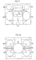
- FIGS. 11 and 12 schematically show a device with two propellants and six tanks which makes it possible to avoid any decentering of the center of mass with respect to the spin axis.
- the storage volumes of each propellant comprise, in addition to the surface tension reservoir 12a or 12b and the wound reservoir 10a or 10b, an additional wound reservoir 52a or 52b, of the same volume and the same shape as the first.
- the location of the tanks can be that indicated in FIGS. 11 and 12, respectively in elevation and in top view.
- the reservoirs 10 and 52 containing the same propellant supply the corresponding reservoir 12 in parallel and are emptied simultaneously during the operation of the apogee engine.
- the reservoirs 10 and 52 can each have a capacity of 130 l and be supplied with helium under a pressure of 18 bars. If reservoirs 12a and 12b are used which have a higher capacity, for example 160 I, it is necessary, to make them work in progressive depressurization during the operation of the nozzles 37, from a helium pressure greater than 18 bars. This result can be achieved by using two regulators 28 or a two-stage regulator, allowing, once the tanks 10 and 52 are emptied, to bring the pressure in the tanks 12 to 22 bars before closing the valves 18.
Description
La présente invention concerne les procédés et dispositifs de propulsion destinés aux satellites.et elle trouve une application particulièrement importante dans le domaine des satellites géostationnaires.The present invention relates to propulsion methods and devices intended for satellites. It finds a particularly important application in the field of geostationary satellites.
Pour injecter un satellite sur son orbite définitive puis assurer son maintien à poste pendant la durée de- vie utile, des moyens de propulsion doivent être prévus. Une tendance qui se manifeste actuellement consiste à prévoir un système de propulsion unifié, qui tout à la fois intervient pour injecter le satellite sur son orbite définitive (rôle rempli antérieurement par un moteur d'apogée à poudre) et pour assurer ensuite le maintien à poste du satellite (rôle rempli par des tuyères alimentées à partir d'un système de stockage d'ergol). En règle générale, on utilise deux ergols, par exemple la monométhylhydra- zine ou MMH comme combustible, le peroxyde d'azote N204 comme oxydant.In order to inject a satellite into its final orbit and then ensure that it remains stationary for the useful life, propulsion means must be provided. A trend that is currently manifesting itself consists in providing a unified propulsion system, which at the same time intervenes to inject the satellite into its final orbit (role previously fulfilled by an apogee powder engine) and then to ensure the retention at post. from the satellite (role filled by nozzles supplied from a propellant storage system). Generally, two propellants are used, for example monomethylhydrazine or MMH as fuel, nitrogen peroxide N 2 0 4 as oxidant.
Des raisons d'encombrement et faisabilité conduisent à utiliser au moins deux réservoirs de stockage pour chaque ergol. Dans les dispositifs existants, les réservoirs contenant un même ergol sont reliés en parallèle par un réseau de tuyauteries. L'une des raisons qui conduisent à ce montage en parallèle est la suivante. La majeure partie (en général plus des trois quarts) des ergols est consommée au cours de la phase d'injection. Le montage en parallèle et le vidage simultané des deux réservoirs permettent de maintenir le centre de masse des ergols sur l'axe de poussée du moteur principal.For reasons of space and feasibility, it is necessary to use at least two storage tanks for each propellant. In existing devices, the tanks containing the same propellant are connected in parallel by a network of pipes. One of the reasons which lead to this parallel mounting is the following. Most (usually more than three-quarters) of the propellants are consumed during the injection phase. The parallel mounting and the simultaneous emptying of the two tanks makes it possible to maintain the center of mass of the propellants on the thrust axis of the main engine.
Mais, en contrepartie, cette disposition présente de nombreux inconvénients: La multiplication des réservoirs augmente le poids et le coût. Les réservoirs doivent pratiquement être redessi- nés pour chaque mission particulière. Les réservoirs ne sont jamais totalement pleins durant le lancement (et l'éventuel tir de périgée depuis la navette spatiale). Tous les réservoirs commençant à se vider dès le début de l'injection sur orbite définitive, un ballotement du liquide dans les réservoirs est à craindre en dépit du cloisonnement possible de ces derniers.However, in return, this arrangement has many drawbacks: The multiplication of tanks increases the weight and the cost. The tanks must practically be redesigned for each particular mission. The tanks are never completely full during launch (and any perigee fire from the space shuttle). All the tanks starting to empty from the start of the injection into final orbit, a sloshing of the liquid in the tanks is to be feared despite the possible partitioning of the latter.
L'invention vise à fournir un procédé et un dispositif de propulsion à ergols pour satellites répondant mieux que ceux antérieurement connus aux exigences de la pratique, notamment en ce que les inconvénients ci-dessus mentionnés sont très atténués.The invention aims to provide a method and a propellant device for propellants for satellites which respond better than those previously known to the requirements of practice, in particular in that the drawbacks mentioned above are greatly reduced.
Pour cela, l'invention part de la constatation que, quel que soit le mode d'injection du satellite sur son orbite définitive, le satellite est soumis à une accélération d'orientation déterminée et elle fait usage de cette accélération pour assurer le puisage des ergols.For this, the invention starts from the observation that, whatever the mode of injection of the satellite into its final orbit, the satellite is subjected to a determined orientation acceleration and it makes use of this acceleration to ensure the drawing of the propellants.
De façon plus précise, l'invention propose un dispositif de propulsion unifié à ergol pour satellites comportant un système de stockage d'ergol ayant au moins deux réservoirs pour l'ergol ou chaque ergol, caractérisé en ce que les réservoirs contenant le même ergol sont montés en série, la contenance du réservoir amont étant inférieure à la consommation d'ergol requise par le moteur d'apogée pour l'injection et ce réservoir amont étant monté de façon que l'accélération au cours de l'injection maintienne l'ergol qu'il contient au contact d'une zone de la paroi munie d'une conduite de sortie d'ergol vers le réservoir placé en aval.More specifically, the invention provides a unified propellant propellant device for satellites comprising an propellant storage system having at least two tanks for the propellant or each propellant, characterized in that the tanks containing the same propellant are connected in series, the capacity of the upstream tank being lower than the consumption of propellant required by the apogee engine for injection and this upstream tank being mounted so that the acceleration during injection maintains the propellant that it contains in contact with an area of the wall provided with a propellant outlet pipe towards the tank placed downstream.
L'invention propose également un procédé de propulsion de satellite par alimentation d'un propulseur d'apogée et de propulseurs de maintien à poste à partir d'un système de stockage d'ergol comprenant au moins deux réservoirs pour l'ergol ou chaque ergol, procédé caractérisé en ce qu'on monte en série les réservoirs contenant un même ergol, en ce qu'on alimente le propulseur d'apogée à partir des réservoirs placés en série en admettant un gaz de pressurisation dans le réservoir amont à partir d'une source de gaz embarquée, et en ce qu'on assure l'alimentation des propulseurs de maintien à poste à partir du réservoir aval après que le réservoir amont ait été vidé par fonctionnement du moteur d'apogée et après séparation des réservoirs amont et aval.The invention also provides a method of propelling a satellite by supplying a pinnacle thruster and station-keeping thrusters from a propellant storage system comprising at least two tanks for the propellant or each propellant , process characterized in that the tanks containing the same propellant are mounted in series, in that the apogee propellant is supplied from the tanks placed in series by admitting a pressurization gas into the upstream tank from an on-board gas source, and in that it ensures the supply of the station-keeping propellants from the downstream tank after the upstream tank has been emptied by operation of the apogee engine and after separation of the upstream and downstream tanks .
Alors que le réservoir aval doit résister à l'action de l'ergol sous pression qu'il contient pendant toute la durée de vie utile du satellite, le réservoir amont n'est pressurisé et en contact avec l'ergol que pendant une durée brève, ne dépassant pas quelques semaines. Ce réservoir amont peut, en conséquence, être constitué de façon beaucoup plus économique et légère que le réservoir aval, ce qui est une source notable d'économie. Au surplus, le réservoir aval peut être aisément standardisé, le réservoir amont, de constitution simple, étant seul modifié en fonction de la mission.While the downstream tank must resist the action of the pressurized propellant it contains throughout the useful life of the satellite, the upstream tank is only pressurized and in contact with the propellant for a short time , not exceeding a few weeks. This upstream tank can therefore be made much more economically and lightly than the downstream tank, which is a significant source of savings. In addition, the downstream tank can be easily standardized, the upstream tank, of simple constitution, being the only one modified according to the mission.
Contrairement à ce qu'on aurait pu penser, l'invention est susceptible d'être mise en oeuvre quel que soit le mode de lancement et d'injection prévu, moyennant un simple choix approprié de l'orientation des réservoirs amont pour tenir compte du sens dans lequel s'exerce l'accélération lors de l'injection. Dans le cas d'un satellite qui est stabilisé suivant trois axes au cours de l'injection, les réservoirs seront orientés de façon que l'accélération uniforme, de sens axial, au cours de l'injection, tende à plaquer l'ergol contre la partie du réservoir munie de la conduite de sortie. Dans le cas où le satellite est stabilisé par rotation autour de son axe longitudinal lors de l'injection (satellites dits « spinnés »), l'accélération centrifuge est prépondérante. Les réservoirs seront placés de façon que cette accélération radiale plaque le liquide contre la partie de la paroi munie de la conduite de sortie.Contrary to what one might have thought, the invention is capable of being implemented regardless of the intended launch and injection mode, with a simple suitable choice of the orientation of the upstream tanks to take account of the direction in which the acceleration is exerted during the injection. In the case of a satellite which is stabilized along three axes during the injection, the reservoirs will be oriented so that the uniform acceleration, of axial direction, during the injection, tends to press the propellant against the part of the tank fitted with the outlet pipe. In the case where the satellite is stabilized by rotation around its longitudinal axis during injection (so-called “spinned” satellites), centrifugal acceleration is predominant. The reservoirs will be placed so that this radial acceleration plates the liquid against the part of the wall provided with the outlet pipe.
L'invention sera mieux comprise à la lecture de . la description qui suit de modes particuliers de réalisation, donnés à titre d'exemples non limitatifs. La description se réfère aux dessins qui l'accompagnent, dans lesquels :
- la Figure 1 est un schéma de principe montrant le dispositif de propulsion dans son ensemble,
- la Figure 2 est un schéma montrant l'implantation des réservoirs autour de l'axe principal du satellite,
- la Figure 3 est un schéma montrant l'emplacement de la sortie des réservoirs amont dans un satellite stabilisé par rotation au cours de l'injection,
- les Figures 4 et 5 montrent schématiquement une constitution interne possible des réservoirs aval,
- les Figures 6a à 6f montrent la disposition des ergols dans leurs réservoirs à plusieurs phases de la mission,
- la Figure 7 montre schématiquement la partie supérieure d'un réservoir amont réduisant le ballotement d'ergol,
- la Figure 8 est un schéma d'implantation des réservoirs utilisable quel que soit le mode de lancement du satellite,
- la Figure 9 est une vue de détail à grande échelle des réservoirs supplémentaires du dispositif de la figure 8,
- les Figures 10, 11 et 12 montrent schématiquement un dispositif à six réservoirs.
- FIG. 1 is a block diagram showing the propulsion device as a whole,
- FIG. 2 is a diagram showing the location of the tanks around the main axis of the satellite,
- FIG. 3 is a diagram showing the location of the outlet of the upstream tanks in a satellite stabilized by rotation during the injection,
- Figures 4 and 5 schematically show a possible internal constitution of the downstream reservoirs,
- Figures 6a to 6f show the arrangement of the propellants in their tanks during several phases of the mission,
- FIG. 7 schematically shows the upper part of an upstream tank reducing the sloshing of propellant,
- FIG. 8 is a layout diagram of the tanks which can be used whatever the satellite launch mode,
- FIG. 9 is a detailed view on a large scale of the additional reservoirs of the device of FIG. 8,
- Figures 10, 11 and 12 schematically show a device with six tanks.
Le dispositif dont la constitution de principe est montrée en figure 1 utilise deux ergols, qu'on supposera être le peroxyde d'azote N204 et la monométhyle hydrazine ou MMH. Les circuits parcourus par les deux ergols sont de constitution identique. Le circuit destiné à recevoir la MMH comporte par exemple un réservoir amont 10a et un réservoir aval 12a. Le réservoir amont 10a ne sera en contact avec l'ergol que pendant les quelques jours ou quelques semaines qui séparent le remplissage de la vidange au cours du transfert, c'est-à-dire lors de l'alimentation du moteur d'apogée. Il pourra être constitué de façon légère, par exemple par une paroi mince de métal compatible avec l'ergol et formable à froid, tel qu'un alliage d'aluminium ou de titane, fretté par un bobinage de fibre enrobée de résine. Il serait impossible d'utiliser un tel réservoir pour le stockage à long terme à cause du risque de corrosion, et surtout à cause du risque de fluage de la résine d'imprégnation de l'enroulement de renforcement sous l'action de la pression interne que la tôle métallique mince du réservoir est incapable de supporter. Le réservoir aval 12a aura au contraire une constitution classique,'à enveloppe de titane allié, et sera équipé d'un dispositif d'expulsion de l'ergol mettant en jeu les forces de capillarité, pour fournir un débit d'ergol exempt de bulles de gaz.The device, the principle of which is shown in FIG. 1, uses two propellants, which will be assumed to be nitrogen peroxide N 2 0 4 and monomethyl hydrazine or MMH. The circuits traversed by the two propellants are of identical constitution. The circuit intended to receive the MMH comprises for example an
La sortie du réservoir 10a est placée de façon à être noyée par l'ergol résiduel en fin de vidange de ce réservoir. Dans le cas d'un transfert sur orbite définitive alors que le satellite est stabilisé suivant trois axes, la sortie sera située dans une direction axiale (direction de la poussée du propulseur d'apogée 14). La sortie du réservoir 10a est reliée au réservoir 12a par une conduite 16a munie d'une vanne d'isolement 18a. On utilisera généralement une vanne pyrotechnique ouverte avant actionnement, qui a l'avantage d'être légère et d'assurer une coupure étanche. Dans le cas d'un satellite stabilisé par rotation, cette conduite 16a pourra se prolonger jusqu'à la zone externe dans le sens radial du volume délimité par le réservoir (figure 3).The outlet of the
Une entrée axiale du réservoir 10a, située à l'opposé de la sortie, est reliée par une conduite 20a munie d'une vanne 22a d'isolement et de moyens anti-retour 24a, à une source d'hélium sous pression. La vanne 22a peut être une vanne pyrotechnique fermée jusqu'à actionnement. La source de gaz de pressurisation peut être constituée par des bouteilles d'hélium sous pression 26 et un détendeur-régulateur 28 réduisant la pression jusqu'à la valeur de pressurisation choisie, par exemple de l'ordre de 18 bars. Ce circuit est complété par des vannes de remplissage et de vidange au sol montrées schématiquement en 30, par des capteurs de pression (non représentés) et par l'une des soupapes de sécurité (non représentées). Une vanne de dépressurisation du réservoir 10a sera avantageusement prévue pour réduire la pression dans le réservoir une fois qu'il est isolé, afin d'éviter un risque d'éclatement et de pollution de l'ensemble du satellite. L'échappement de cette vanne doit s'effectuer de façon symétrique pour éviter de créer des forces ou couples écartant le satellite de sa position nominale.An axial inlet of the
Lorsque les deux ergols ont des masses volumiques différentes, ce qui est le cas le plus fréquent, les réservoirs doivent être implantés non pas à intervalles réguliers, mais en des emplacements qui maintiennent un équilibrage satisfaisant au cours de la vidange. La figure 2 montre à titre d'exemple une disposition utilisable lorsque les ergols sont la monométhylhydra- zine et NZ04, pour lesquels le rapport des masses volumiques est de 1,64 à 20 °C.When the two propellants have different densities, which is the most frequent case, the tanks must be installed not at regular intervals, but in locations which maintain a satisfactory balance during emptying. FIG. 2 shows by way of example an arrangement which can be used when the propellants are monomethylhydrazine and N Z 0 4 , for which the density ratio is 1.64 at 20 ° C.
Les réservoirs 12a et 12b alimentent, par l'intermédiaire de filtres 32a et 32b, des collecteurs respectifs 34a et 34b. Sur ces collecteurs sont branchés, d'une part, le moteur d'apogée 14 muni d'une vanne de commande électromagnétique 36, d'autre part, les diverses tuyères 37, également munies d'électrovannes 38 permettant de les alimenter à partir de l'un ou l'autre des collecteurs. Des vannes d'isolement bistables 39 sont prévues sur les collecteurs pour permettre de séparer un jeu de tuyères 37 de l'alimentation en cas de défaillance. Les tuyères sont avantageusement en nombre suffisant pour assurer la redondance nécessaire à la sécurité d'emploi.The
Un dispositif anti-retour est placé entre les réservoirs pour éviter le retour d'ergol vers le réservoir amont 10a une fois celui-ci épuisé, alors . que la vanne 18a n'a pas encore été fermée. Ce dispositif peut être placé dans la conduite de liaison 16a. Toutefois, il peut être intégré au réservoir aval et être constitué par le filtre qui est de toute façon nécessaire, par exemple sous forme d'une toile filtrante à mailles fines (de l'ordre de 10 µ) placée à l'entrée du réservoir.A non-return device is placed between the tanks to prevent the return of propellant to the
Le réservoir aval 12a peut avoir la constitution interne classique des réservoirs antérieurs à tension de surface permettant une vidange complète. Ces réservoirs sont équipés intérieurement d'un dispositif dirigeant, par capillarité, l'ergol vers la sortie. Une solution plus avantageuse utilise le fait qu'à la fin du fonctionnement du moteur d'apogée le réservoir 10a est partiellement (habituellement aux deux tiers) vide. Cette solution consiste à fractionner le réservoir 12a en deux volumes par une cloison, oblique pour permettre une vidange complète, munie d'un passage situé au point bas et munie d'une toile métallique de retenue ou d'un dispositif tampon à capillarité. La cloison 42 sépare un volume supérieur d'un volume inférieur et elle est placée de façon que seul ce dernier contienne de l'ergol à la fin du fonctionnement du moteur d'apogée. Une variation de température peut faire passer un faible volume d'ergol du réservoir inférieur vers le réservoir supérieur, avant que les températures ne s'équilibrent. Le rôle du dispositif tampon est de retenir l'ergol sortant du volume inférieur, puis de le restituer à ce volume. Cette disposition permet de n'équiper d'un dispositif capillaire que le volume inférieur.The
Le dispositif tampon peut être constitué par des ailettes métalliques en éventail 40 entourant le trou ménagé dans la cloison de séparation 42 (ftgure 4). Il peut aussi bien être constitué par une bande métallique 44 enroulée en spirale, dont les spires se resserrent progressivement vers le centre où se place le trou de traversée de la cloison 42 (figure 5).The buffer device can be constituted by fan-shaped
Un procédé de mise en oeuvre du dispositif de propulsion suivant l'invention sera maintenant décrit en faisant référence aux figures 6a à 6f.A method of implementing the propulsion device according to the invention will now be described with reference to FIGS. 6a to 6f.
Les réservoirs sont tout d'abord purgés, puis remplis au sol suivant le trajet indiqué par les flèches en figure 6a, la partie haute des réservoirs 12a et 12b étant mise à la décharge. Ce remplissage, effectué alors que les vannes 22a et 22b sont fermées, est arrêté lorsque l'espace occupé par le gaz dans les réservoirs amont 10a et 10b est celui préalablement calculé pour permettre de tolérer les dilatations thermiques différentielles de l'ergol et de la paroi du réservoir sans risque de rupture ou de déformation de ce dernier.The tanks are first purged, then filled on the ground along the path indicated by the arrows in FIG. 6a, the upper part of the
En cas de lancement par fusée, les ergols restent plaqués dans la même direction lors du tir et lors du passage sur orbite de transfert, du fait de l'existence d'une accélération axiale. Les ergols ne peuvent balloter dans les réservoirs aval 12a et 12b. Le ballotement dans les réservoirs amont au cours du lancement, puis des transferts et de la circulation libre sur orbite de transfert (où aucune accélération ne s'exerce) jusqu'au fonctionnement du moteur d'apogée peut être réduit en prévoyant un système de cloisons ou de chicanes dans les réservoirs. Ces chicanes sont placées pour séparer une zone qui reste entièrement remplie d'ergol, quelle que soit la température, d'une zone contenant du gaz et une fraction de l'ergol aussi faible que possible, mais noyant le débouché de la communication avec la première zone, quelle que soit la température.In the event of launching by rocket, the propellants remain plated in the same direction during the firing and during the passage on orbit of transfer, because of the existence of an axial acceleration. The propellants cannot wobble in the
Dans le cas d'un lancement par fusée, avec stabilisation ultérieure suivant trois axes ou par rotation, on peut utiliser la disposition montrée en figure 7. La cloison 46, oblique, est placée de façon que le niveau N, de l'ergol à la température minimum reste suffisant pour noyer le débouché d'un tube de communication ascendant 48. Le volume de la zone située au-dessus de la cloison 46 est tel que, lorsque l'ergol atteint le niveau N2, à la température maximale, la pression dans le réservoir 10a reste acceptable. Dans la pratique, ce résultat sera atteint en donnant au compartiment situé au-dessus de la cloison 46, un volume de l'ordre de 4 % de celui de l'autre.In the case of a rocket launch, with subsequent stabilization along three axes or by rotation, the arrangement shown in FIG. 7 can be used. The
Dans le cas d'un satellite lancé par fusée, l'absence d'accélération lors de la circulation libre sur orbite de transfert fait que les ergols peuvent prendre n'importe quelle position dans les réservoirs amont, la pire situation pour l'allumage ultérieur du moteur d'apogée étant celle montrée en figure 6b où les conduites 16a et 16b débouchent dans l'atmosphère d'hélium des réservoirs 10a et 10b. Cette situation n'empêche pourtant pas l'allumage du moteur d'apogée. Elle provoque simplement le passage d'une faible quantité d'hélium de pressurisation dans les réservoirs aval 12a et 12b lors de l'ouverture des vannes d'alimentation du moteur d'apogée. Au cours de la phase initiale de l'injection, l'hélium qui est passé dans les réservoirs aval, chasse les ergols qu'ils contiennent vers le moteur d'apogée (figure 6c). Puis l'accélération, axiale dans le cas d'un moteur stabilisé suivant trois axes (figure 6d), radiale dans le cas d'un satellite stabilisé par rotation (figure 6e), vide progressivement les réservoirs amont 10a et 10b. Dans le cas d'un satellite stabilisé par rotation, la vidange complète peut être obtenue en utilisant la disposition montrée en figure 3. Il faut remarquer au passage que la disposition autorise la vidange complète, même dans le cas d'un angle de nutation important, pouvant même atteindré 90° (situation fréquemment dénommée « spin à plat »).In the case of a rocket launched satellite, the absence of acceleration during free circulation in transfer orbit means that the propellants can take any position in the upstream tanks, the worst situation for subsequent ignition of the apogee motor being that shown in FIG. 6b where the
Une fois vidés les réservoirs amont 10a et 10b, les réservoirs aval 12a et 12b se vident progressivement à leur tour pour alimenter le moteur d'apogée. Pendant ce fonctionnement, les vannes 22a et 22b restent ouvertes pour que la pressurisation soit assurée par les bouteilles d'hélium 26 à travers le détenteur 28. Jusqu'à l'issue du fonctionnement du moteur d'apogée 14, les vannes 18a et 18b restent ouvertes, les reflux d'hélium étant interdits par les dispositifs anti-retour placés sur les conduites 16a et 16b et par le débit d'hélium. Comme on l'a indiqué plus - haut, le dispositif anti-retour sera généralement basé sur les forces de capilarité et constitué par exemple par une toile métallique ayant une maille de l'ordre de 10 µ qui interdit aux gaz de passer lorsque la toile est mbuillée par l'ergol et que la différence de pression est inférieure à une valeur de l'ordre de 100 mbars. Après arrêt du moteur d'apogée, les vannes pyrotechniques 18a et 18b sont fermées et séparent définitivement les réservoirs. A partir de ce moment, les réservoirs 12a et 12b fonctionnent en dépressurisation progressive depuis la valeur initiale, généralement de 18 bars. Les vannes 22a et 22b sont fermées et on dépressurise généralement les réservoirs 10a et 10b par ouverture d'une vanne d'évacuation de l'hélium résiduel, de façon symétrique pour ne pas modifier l'attitude du satellite (Fig. 6f).Once the
Ultérieurement, l'ergol résiduel contenu dans les réservoirs 12a et 12b, sera utilisé pour alimenter les tuyères d'orientation et de remise à poste.Subsequently, the residual propellant contained in the
Le montage indiqué en figure 7 n'est pas approprié au cas d'un lancement par navette spatiale. On sait en effet que, dans ce cas, la séparation du satellite muni du moteur de périgée et de la navette s'effectue par largage vers l'arrière, ce qui conduit le satellite à prendre une orbite plus basse que la navette. Le moteur de périgée est ensuite allumé lorsque le satellite se trouve dans le plan équatorial terrestre. L'accélération due au lancement à partir de la navette est alors orientée à 90° de l'accélération due à l'action des moteurs de périgée et d'apogée.The assembly indicated in FIG. 7 is not suitable in the case of a launch by space shuttle. It is known in fact that, in this case, the separation of the satellite provided with the perigee motor and the shuttle is effected by rearward dropping, which leads the satellite to take a lower orbit than the shuttle. The perigee motor is then turned on when the satellite is in the Earth's equatorial plane. The acceleration due to launch from the shuttle is then oriented 90 ° from the acceleration due to the action of the perigee and apogee motors.
Les figures 8 et 9 montrent une disposition qui est utilisable quel que soit le mode de lancement, par satellite ou par navette, et le mode de stabilisation ultérieure. Le dispositif comporte alors, en plus des réservoirs 10a-10b et 12a-12b, deux capacités supplémentaires 50a et 50b dont le volume doit répondre aux mêmes critères que celui du compartiment supérieur constituant vase d'expansion dans le cas de la figure 7. Ces capacités sont de révolution, d'axe à 45° environ des directions '11 et '12 des accélérations lors du lancement par navette et par fusée et lors du fonctionnement du moteur d'apogée. Les parties terminales au moins sont coniques, avec un demi-angle au sommet inférieur à 45°, égal par exemple à 30°, afin que l'emplacement de la sortie corresponde toujours à un point bas.Figures 8 and 9 show an arrangement which can be used regardless of the launch mode, satellite or shuttle, and the subsequent stabilization mode. The device then comprises, in addition to the
Les figures 10, 11 et 12 montrent schématiquement un dispositif à deux ergols et six réservoirs qui permet d'éviter tout décentrement du centre de masse par rapport à l'axe de spin. Sur le schéma de la figure 10, on voit que les volumes de stockage de chaque ergol comportent, en plus du réservoir à tension de surface 12a ou 12b et du réservoir bobiné 10a ou 10b, un réservoir bobiné supplémentaire 52a ou 52b, de même volume et de même forme que le premier. L'implantation des réservoirs peut être celle indiquée sur les figures 11 et 12, respectivement en élévation et en vue de dessus. Les réservoirs 10 et 52 contenant un même ergol alimentent en parallèle le réservoir 12 correspondant et se vident simultanément pendant le fonctionnement du moteur d'apogée. Dans un mode d'exécution représentatif d'un dispositif de lancement de satellite existant, les réservoirs 10 et 52 peuvent avoir chacun une contenance de 130 1 et être alimentés en hélium sous une pression de 18 bars. Si on utilise des réservoirs 12a et 12b ayant une contenance supérieure, par exemple de 160 I, il faut, pour les faire travailler en dépressurisation progressive lors du fonctionnement des tuyères 37, partir d'une pression d'hélium supérieure à 18 bars. Ce résultat peut être atteint en utilisant deux détendeurs 28 ou un détendeur à deux niveaux, permettant, une fois les réservoirs 10 et 52 vidés, d'amener la pression dans les réservoirs 12 à 22 bars avant fermeture des vannes 18.Figures 10, 11 and 12 schematically show a device with two propellants and six tanks which makes it possible to avoid any decentering of the center of mass with respect to the spin axis. In the diagram in FIG. 10, it can be seen that the storage volumes of each propellant comprise, in addition to the
Dans ces conditions, le centre de masse du dispositif de propulsion évolue pratiquement de la position G, lorsque le satellite est sur orbite de transfert ayant allumage du moteur d'apogée, à la position G2 lors de la venue à poste sur orbite géostationnaire (Figure 11).Under these conditions, the center of mass of the propulsion system practically evolves from position G, when the satellite is in transfer orbit with ignition of the apogee engine, to position G 2 when coming to station in geostationary orbit ( Figure 11).
Claims (9)
Applications Claiming Priority (2)
| Application Number | Priority Date | Filing Date | Title |
|---|---|---|---|
| FR8220953 | 1982-12-14 | ||
| FR8220953A FR2537544B1 (en) | 1982-12-14 | 1982-12-14 | PROPULSION METHOD AND DEVICE FOR SATELLITES |
Publications (2)
| Publication Number | Publication Date |
|---|---|
| EP0113622A1 EP0113622A1 (en) | 1984-07-18 |
| EP0113622B1 true EP0113622B1 (en) | 1986-07-30 |
Family
ID=9280085
Family Applications (1)
| Application Number | Title | Priority Date | Filing Date |
|---|---|---|---|
| EP19830402424 Expired EP0113622B1 (en) | 1982-12-14 | 1983-12-14 | Method and device to propel space craft |
Country Status (3)
| Country | Link |
|---|---|
| EP (1) | EP0113622B1 (en) |
| DE (1) | DE3365023D1 (en) |
| FR (1) | FR2537544B1 (en) |
Families Citing this family (15)
| Publication number | Priority date | Publication date | Assignee | Title |
|---|---|---|---|---|
| US4609169A (en) * | 1984-08-14 | 1986-09-02 | The United States Of America As Represented By The Secretary Of The Air Force | Propellant tank resupply system |
| FR2585669B1 (en) * | 1985-08-05 | 1987-11-27 | Barkats Gerard | BI-LIQUID PROPULSIVE SYSTEM OF AN ARTIFICIAL SATELLITE AND USE OF SAID SATELLITE EJECTION SYSTEM |
| FR2629913B1 (en) * | 1988-04-06 | 1991-08-02 | Europ Agence Spatiale | METHOD AND SYSTEM FOR EVALUATING THE RESIDUAL QUANTITY OF FUEL IN A SPATIONEF TANK |
| FR2656381B1 (en) * | 1989-12-22 | 1994-06-03 | Aerospatiale | LIQUID ERGOL SUPPLY DEVICE FOR A SPACE VEHICLE, SUITABLE FOR PREDICTING END OF LIFE. |
| FR2664562B1 (en) * | 1990-07-13 | 1996-03-08 | Aerospatiale | GEOSTATIONARY-TYPE SATELLITE HAVING A HANDLING SYSTEM HAVING A COMBINATION WITH LIQUID ERGOLS AND MULTIPLE TUYERES. |
| FR2658782B1 (en) * | 1990-02-26 | 1992-07-03 | Aerospatiale | GEOSTATIONARY-TYPE OBSERVATION SATELLITE HAVING A HANDLING SYSTEM HAVING A COMBINATION WITH LIQUID ERGOLS AND MULTIPLE TUYERES. |
| DE69100603T2 (en) * | 1990-02-26 | 1994-03-10 | Aerospatiale | Geostationary observation satellite with a multi-nozzle liquid fuel-driven apogee maneuvering system. |
| US5282357A (en) * | 1990-04-19 | 1994-02-01 | Trw Inc. | High-performance dual-mode integral propulsion system |
| DE4217051C2 (en) * | 1992-05-22 | 1994-03-10 | Deutsche Aerospace | Fuel supply system for rocket engines |
| FR2697587B1 (en) * | 1992-11-04 | 1995-01-20 | Europ Propulsion | Optimized rocket motor power supply system. |
| CN109305388A (en) * | 2018-03-09 | 2019-02-05 | 哈尔滨工业大学 | A kind of aircraft portrait center of gravity auto-scheduling system based on water counterweight |
| CN112459925B (en) * | 2020-11-02 | 2022-03-04 | 中国运载火箭技术研究院 | Built-in baffle type storage box |
| CN114476141B (en) * | 2021-12-17 | 2024-04-09 | 上海空间推进研究所 | Lunar landing aircraft propulsion method and system |
| CN114872936A (en) * | 2022-07-11 | 2022-08-09 | 北京宇航推进科技有限公司 | Satellite orbit control power system |
| CN115402536B (en) * | 2022-08-19 | 2023-04-07 | 南京理工大学 | Rapid racemization electric heating jet type micro-propulsion system for space instability target |
-
1982
- 1982-12-14 FR FR8220953A patent/FR2537544B1/en not_active Expired
-
1983
- 1983-12-14 DE DE8383402424T patent/DE3365023D1/en not_active Expired
- 1983-12-14 EP EP19830402424 patent/EP0113622B1/en not_active Expired
Also Published As
| Publication number | Publication date |
|---|---|
| EP0113622A1 (en) | 1984-07-18 |
| DE3365023D1 (en) | 1986-09-04 |
| FR2537544B1 (en) | 1985-07-19 |
| FR2537544A1 (en) | 1984-06-15 |
Similar Documents
| Publication | Publication Date | Title |
|---|---|---|
| EP0113622B1 (en) | Method and device to propel space craft | |
| EP3083406B1 (en) | Method and system for transferring a satellite from an initial orbit into a mission orbit | |
| EP0132175B1 (en) | Container for storing liquids using a capillary confinement | |
| EP0232349B1 (en) | Bi-liquid propulsive system for an artificial satellite and utilization of said system for ejecting the satellite | |
| FR2484961A1 (en) | SURFACE TANK | |
| EP1241341A1 (en) | Cryotechnic propulsion module | |
| EP0522954B1 (en) | Surface tension vessel with multiple output flow | |
| FR2931802A1 (en) | SATELLITE, SATELLITE CONTROL METHOD, AND PROGRAM. | |
| JP2008189304A (en) | Cryogenic liquid and tank for storing storable fuel | |
| EP2974966B1 (en) | Propulsion device for satellite allowing the passive removal of propellant gas | |
| EP1902757B1 (en) | Propulsion device for an agent contained in a cavity | |
| WO2006106204A2 (en) | Two-phase cold gas propulsion system and tank for such a space craft propulsion system | |
| FR2697587A1 (en) | Optimized rocket motor power supply system. | |
| EP3765368B1 (en) | System for placing a satellite in working orbit | |
| EP1807621B1 (en) | Device for the supply of a rocket motor with fuel and oxidiser | |
| EP3071825B1 (en) | Device for suppling propellant to a propulsive rocket engine chamber | |
| FR2655943A1 (en) | ADAPTABLE SYSTEM FOR STORING LIQUID UNDER PRESSURE AND APPLICATION TO THE STORAGE OF AN ERGOL IN A SPATIAL VEHICLE. | |
| WO2006056716A1 (en) | Assembly for a spacecraft propulsion system and propulsion system comprising at least one such assembly | |
| EP2471715B1 (en) | Augmentation of a monopropellant propulsion system | |
| FR2636095A1 (en) | System for supplying the boosters of an artificial satellite with at least one liquid ergol | |
| EP2221250B1 (en) | Device and method for coupling a propulsion system and a fuel cell | |
| EP3328737B1 (en) | Satellite aerobraking and passivation device and method | |
| FR2997387A1 (en) | Astronautic launcher for launching e.g. space exploration probes of international space station in orbit of satellite, has main body whose tank supplies propellant to auxiliary rocket engine, and auxiliary booster separable from main body |
Legal Events
| Date | Code | Title | Description |
|---|---|---|---|
| PUAI | Public reference made under article 153(3) epc to a published international application that has entered the european phase |
Free format text: ORIGINAL CODE: 0009012 |
|
| AK | Designated contracting states |
Designated state(s): DE GB IT NL |
|
| 17P | Request for examination filed |
Effective date: 19840625 |
|
| GRAA | (expected) grant |
Free format text: ORIGINAL CODE: 0009210 |
|
| AK | Designated contracting states |
Kind code of ref document: B1 Designated state(s): DE GB IT NL |
|
| ITF | It: translation for a ep patent filed |
Owner name: ING. C. GREGORJ S.P.A. |
|
| REF | Corresponds to: |
Ref document number: 3365023 Country of ref document: DE Date of ref document: 19860904 |
|
| PLBI | Opposition filed |
Free format text: ORIGINAL CODE: 0009260 |
|
| 26 | Opposition filed |
Opponent name: ERNO RAUMFAHRTTECHNIK GMBH Effective date: 19870429 |
|
| NLR1 | Nl: opposition has been filed with the epo |
Opponent name: ERNO RAUMFAHRTTECHNIK GMBH |
|
| PLBN | Opposition rejected |
Free format text: ORIGINAL CODE: 0009273 |
|
| STAA | Information on the status of an ep patent application or granted ep patent |
Free format text: STATUS: OPPOSITION REJECTED |
|
| 27O | Opposition rejected |
Effective date: 19880617 |
|
| NLR2 | Nl: decision of opposition | ||
| ITTA | It: last paid annual fee | ||
| PGFP | Annual fee paid to national office [announced via postgrant information from national office to epo] |
Ref country code: NL Payment date: 19961125 Year of fee payment: 14 |
|
| PGFP | Annual fee paid to national office [announced via postgrant information from national office to epo] |
Ref country code: DE Payment date: 19961202 Year of fee payment: 14 |
|
| PGFP | Annual fee paid to national office [announced via postgrant information from national office to epo] |
Ref country code: GB Payment date: 19961206 Year of fee payment: 14 |
|
| PG25 | Lapsed in a contracting state [announced via postgrant information from national office to epo] |
Ref country code: GB Free format text: LAPSE BECAUSE OF NON-PAYMENT OF DUE FEES Effective date: 19971214 |
|
| PG25 | Lapsed in a contracting state [announced via postgrant information from national office to epo] |
Ref country code: NL Free format text: LAPSE BECAUSE OF NON-PAYMENT OF DUE FEES Effective date: 19980701 |
|
| GBPC | Gb: european patent ceased through non-payment of renewal fee |
Effective date: 19971214 |
|
| NLV4 | Nl: lapsed or anulled due to non-payment of the annual fee |
Effective date: 19980701 |
|
| PG25 | Lapsed in a contracting state [announced via postgrant information from national office to epo] |
Ref country code: DE Free format text: LAPSE BECAUSE OF NON-PAYMENT OF DUE FEES Effective date: 19980901 |