EP0113490B1 - Gear box for a vehicle - Google Patents
Gear box for a vehicle Download PDFInfo
- Publication number
- EP0113490B1 EP0113490B1 EP83300039A EP83300039A EP0113490B1 EP 0113490 B1 EP0113490 B1 EP 0113490B1 EP 83300039 A EP83300039 A EP 83300039A EP 83300039 A EP83300039 A EP 83300039A EP 0113490 B1 EP0113490 B1 EP 0113490B1
- Authority
- EP
- European Patent Office
- Prior art keywords
- shaft
- gear
- gearbox
- gearbox according
- drive
- Prior art date
- Legal status (The legal status is an assumption and is not a legal conclusion. Google has not performed a legal analysis and makes no representation as to the accuracy of the status listed.)
- Expired
Links
Images

Classifications
-
- B—PERFORMING OPERATIONS; TRANSPORTING
- B60—VEHICLES IN GENERAL
- B60K—ARRANGEMENT OR MOUNTING OF PROPULSION UNITS OR OF TRANSMISSIONS IN VEHICLES; ARRANGEMENT OR MOUNTING OF PLURAL DIVERSE PRIME-MOVERS IN VEHICLES; AUXILIARY DRIVES FOR VEHICLES; INSTRUMENTATION OR DASHBOARDS FOR VEHICLES; ARRANGEMENTS IN CONNECTION WITH COOLING, AIR INTAKE, GAS EXHAUST OR FUEL SUPPLY OF PROPULSION UNITS IN VEHICLES
- B60K17/00—Arrangement or mounting of transmissions in vehicles
- B60K17/28—Arrangement or mounting of transmissions in vehicles characterised by arrangement, location, or type of power take-off
-
- F—MECHANICAL ENGINEERING; LIGHTING; HEATING; WEAPONS; BLASTING
- F16—ENGINEERING ELEMENTS AND UNITS; GENERAL MEASURES FOR PRODUCING AND MAINTAINING EFFECTIVE FUNCTIONING OF MACHINES OR INSTALLATIONS; THERMAL INSULATION IN GENERAL
- F16H—GEARING
- F16H37/00—Combinations of mechanical gearings, not provided for in groups F16H1/00 - F16H35/00
- F16H37/02—Combinations of mechanical gearings, not provided for in groups F16H1/00 - F16H35/00 comprising essentially only toothed or friction gearings
- F16H37/04—Combinations of toothed gearings only
- F16H37/042—Combinations of toothed gearings only change gear transmissions in group arrangement
- F16H37/046—Combinations of toothed gearings only change gear transmissions in group arrangement with an additional planetary gear train, e.g. creep gear, overdrive
-
- F—MECHANICAL ENGINEERING; LIGHTING; HEATING; WEAPONS; BLASTING
- F16—ENGINEERING ELEMENTS AND UNITS; GENERAL MEASURES FOR PRODUCING AND MAINTAINING EFFECTIVE FUNCTIONING OF MACHINES OR INSTALLATIONS; THERMAL INSULATION IN GENERAL
- F16H—GEARING
- F16H3/00—Toothed gearings for conveying rotary motion with variable gear ratio or for reversing rotary motion
- F16H3/02—Toothed gearings for conveying rotary motion with variable gear ratio or for reversing rotary motion without gears having orbital motion
- F16H3/08—Toothed gearings for conveying rotary motion with variable gear ratio or for reversing rotary motion without gears having orbital motion exclusively or essentially with continuously meshing gears, that can be disengaged from their shafts
- F16H2003/0826—Toothed gearings for conveying rotary motion with variable gear ratio or for reversing rotary motion without gears having orbital motion exclusively or essentially with continuously meshing gears, that can be disengaged from their shafts wherein at least one gear on the input shaft, or on a countershaft is used for two different forward gear ratios
-
- Y—GENERAL TAGGING OF NEW TECHNOLOGICAL DEVELOPMENTS; GENERAL TAGGING OF CROSS-SECTIONAL TECHNOLOGIES SPANNING OVER SEVERAL SECTIONS OF THE IPC; TECHNICAL SUBJECTS COVERED BY FORMER USPC CROSS-REFERENCE ART COLLECTIONS [XRACs] AND DIGESTS
- Y10—TECHNICAL SUBJECTS COVERED BY FORMER USPC
- Y10T—TECHNICAL SUBJECTS COVERED BY FORMER US CLASSIFICATION
- Y10T74/00—Machine element or mechanism
- Y10T74/19—Gearing
- Y10T74/19219—Interchangeably locked
- Y10T74/19377—Slidable keys or clutches
- Y10T74/19386—Multiple clutch shafts
- Y10T74/19405—Multiple forward and reverse
-
- Y—GENERAL TAGGING OF NEW TECHNOLOGICAL DEVELOPMENTS; GENERAL TAGGING OF CROSS-SECTIONAL TECHNOLOGIES SPANNING OVER SEVERAL SECTIONS OF THE IPC; TECHNICAL SUBJECTS COVERED BY FORMER USPC CROSS-REFERENCE ART COLLECTIONS [XRACs] AND DIGESTS
- Y10—TECHNICAL SUBJECTS COVERED BY FORMER USPC
- Y10T—TECHNICAL SUBJECTS COVERED BY FORMER US CLASSIFICATION
- Y10T74/00—Machine element or mechanism
- Y10T74/21—Elements
- Y10T74/2186—Gear casings
Definitions
- the present invention relates to a gearbox for a vehicle including a PTO shaft (power take-off shaft).
- the gearbox is of the type known as a trans-axle, that is to say it incorporates a differential and half-shafts of an axle, as well as a change speed gear.
- gearbox which is suitable for incorporation in a vehicle with a frame and which is of such a construction that manufacture and servicing are realtively easy and inexpensive.
- construction is such that a modular approach to manufacture may be adopted, whereby a range of gearboxes can be provided with the incorporation or omission of various optional facilities. This makes it possible to provide a wide range of vehicles of varying degrees of sophistication, as well as different sizes and powers, without the expense of manufacturing individually designed gearboxes.
- CH 67048 describes an automobile with a gearbox having a main shaft, a countershaft and a transverse axle all journalled in the parting plane of a casing with upper and lower casing parts.
- the components can thus readily be assembled into the bottom casing part, the upper part being thereafter fitted.
- Servicing as well as manufacture is simplified.
- the gearbox is a non-structural part mounted in a framed vehicle.
- the object of the present invention is to provide a gearbox which also incoporates a PTO shaft in an advantageous manner and which is capable of providing extensive facilities even within the confines of a narrow vehicle (such as for use in vineyards and orchards), e.g. a large number of gear ratios, a transverse differential on the rear axle, and a longitudinal differential dividing power between the front and rear axle.
- a narrow vehicle such as for use in vineyards and orchards
- Some tractors employ a six speed change speed gearbox and a three speed range gear giving eighteen normal gears. Such a range of gears will typically give road speeds from 1.5 km/ h up to 30 km/h assuming that the gears are sufficiently closely spaced. 30 km/h is a very low speed for travelling on the road and it is desirable to achieve a top speed more like 40 km/h. This necessates even more gears.
- the starting point of the present invention is a gearbox for a vehicle comprising a change-speed gear having a main shaft connectible to an input to the gearbox and a countershaft on first and second longitudinal shaft lines respectively, an axle drive on a third, transverse shaft line, and a casing enclosing the change-speed gear and the axle drive and having bottom and top parts with a parting plane which contains the first, second and third shaft lines.
- the invention is characterised in that the axle drive has two half-shafts driven by a transverse differential from an output component on one of the longitudinal shaft lines, and by a PTO shaft set above or below the parting plane and journalled through the top or bottom casing part, and means coupling the PTO shaft to a component on one of the longitudinal shaft lines.
- the nature of the casing allows the internal components of the gear box to be assembled into the bottom casing part, the top part thereof being fitted. Servicing the gearbox is also easy, by removal of the top casing part.
- the PTO shaft is not in the parting plane to avoid interference with the half-shafts. Instead, the PTO shaft is set above or below the parting plane and is journalled through one casing part.
- An input shaft advantageously extends through the hollow main shaft to a reduction gear coupling the input shaft to the PTO shaft.
- the casing can be recessed around the end of the PTO shaft to achieve a longitudinally compact arrangement and maximise the length of the Cardan shaft.
- the gearbox casing is preferably cast mainly without recesses or re-entrant parts in order to simplify casting.
- Light weight, cast shells, preferably of aluminium, can be employed when the gearbox is not a structural item but is supported by the vehicle frame.
- the change-speed gear preferably provides drive to an intermediate shaft on the first shaft line and thence to an output shaft on the seocnd shaft line by way of forward and reverse gears.
- a coupling engageable directly between the countershaft and the output shaft provides the further range of forward gears.
- the countershaft and output shaft can be hollow to enable a forward drive shaft to pass therethrough for a mechanical front wheel drive.
- a front wheel brake can act on the forward drive shaft and preferably has the same construction as rear wheel brakes on the halfshafts.
- a longitudinal differential is employed to divide power flow between the front and rear axles and this differential may be an epicyclic gear with a hydraulic lock.
- the ratio of the epicyclic gear between the front and rear drives can be selected to correspond to the diameters of the front and rear wheels and the final drive reduction ratios on the two axles.
- the main range of speeds available in both and forward and reverse can be provided by the change-speed gear (e.g. 4 speeds) in conjunction with a range or splitter gear wich can have an optionally selected number of epicyclic stages in accordance with the range of speeds required for a particular application.
- the stages of these epicyclic gears and also a preliminary epicyclic gear can use the same wheels in order to rationalize production.
- the preliminary gear can be utilized to establish the correct input torque, while the power through the gearbox is adapted to the vehicle size by the speed at which the gearbox is driven.
- the change speed is preferably a top-shaft synchronized gear of a construction known in itself, e.g. from our published British patent specification GB 2046853.
- the gearbox has a main casing with a bottom 10 and a top part 11. These two parts are held together in any suitable manner, as symbolised by flanges 12. At the front of the gearbox there is an optional front casing with bottom and top parts 13, 14 attached to the main casing as indicated by flanges 15.
- the gearbox is driven from the engine by an engine shaft 20 which lies on a first shaft line I which is also the line of the main shaft of the gearbox.
- the second shaft line II i.e. the line of the countershaft, is parallel to and at the same horizontal level as the first shaft line I.
- a third, transverse shaft line III defines the rear axle denoted in Fig. 1 by the left-hand half-shaft 21.
- Fig. 1 also shows a PTO shaft 22 which does not lie in the parting plane in order to avoid interference with the axle. As illustrated the PTO shaft is set below the parting plane in the bottom casing part 10 but it could equally well be set above the parting plane in the casing part 11.
- Fig. 1 also shows an optional feature according to which the casing part 10 is recessed at 23 so that the stub end of the PTO shaft is largely shrouded within the gearbox casing and a longitudinally compact arrangement is achieved. This increases the length available for the Cardan Shaft between the PTO shaft and an implement. In general however it is preferred to avoid recessed portions so that the casing parts can be cast easily without the need for corresponding casting cores.
- the casing can be relatively light weight and be cast as a shell. Even if the material is cast iron the weight of the casing will be small compared with that of the gearbox which is a structural component of a tractor. It is preferred nevertheless to use a cast aluminium for the casing parts because of the various advantages of this metal. These include reduction in weight, the ability to cast more thinly than is possible with iron, the absence of corrosion and need for painting and good heat dissipation which may even avoid the need for a transmission oil cooler.
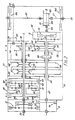
- Fig. 2 is a plan view of the gearbox with the top casing parts 11 and 14 removed. Also Fig. 2 shows the PTO shaft 22 without the recess 23 of Fig. 1. The shaft lines I, II and III are readily apparent in Fig. 2 as are the partitions 24.
- the engine shaft input to the gearbox 20 drives an input shaft 30 by way of a speed reducer or amplifier gear 31.
- a speed reducer or amplifier gear 31 As illustrated this is an epicyclic gear with a brake 33 on its annulus.
- the brake 33 When the brake 33 is operated, the input shaft 30 is driven with reduction in speed and the gear 31 may thus be used as a creep gear.
- an alternative configuration could provide speed amplification, for reasons explained below.
- Direct drive on the engine shaft 20 to the input shaft 30 is achieved by engaging a clutch 32 instead of the brake 33.
- the preliminary gear 31 is one of the optional features of the gearbox and, if this gear is omitted the front housing part 13, 14 can also be omitted, the shaft 20 being coupled directly to the shaft 30.
- a range gear referred to as a splitter gear 35 which provides high, medium and low speed ranges for the main shaft 36 itself of a four-speed change-speed gear 37.
- the main shaft 36 is hollow and the input shaft 30 continues through the main shaft to a gear 38 in mesh with another gear 39 which is on the PTO shaft line and can be engaged to the PTO shaft by a PTO clutch 40.
- the gears 38 and 39 form a reduction gear.
- the splitter gear 35 will be described in more detail below.
- the description of the overall layout of the gearbox continues with consideration of the change-speed gear 37 which comprises the main shaft 36 on the shaft line I, a hollow countershaft 45 on the second shaft line II and a hollow intermediate shaft 46 on the first shaft line I, the input shaft 30 extending through the intermediate shaft 46 as well as the main shaft 36.
- the intermediate shaft 46 is the output shaft of the change-speed gear 37 which is a four-speed, top-shaft synchronized gear of known form, well proven as a compact and advantageous gear for heavy duty gearboxes.
- Three input gears 47 are loose on the main shaft 36 and a fourth gear 48 is fast with the intermediate shaft 46.
- gears 47, 48 are in constant mesh with four gears 49 intergral with the countershaft 45.
- Two synchronized coupling sleeves 50 enable any one of the four gears 47, 48 to be rendered rotationaly fast with the main shaft 36 establishing the four speeds of the change-speed gear 37.
- the fourth speed is a direct drive to the intermediate shaft 46 since the gear 48 is fast with the intermediate shaft 46.
- drive is from the selected gear 47 to the corresponding countershaft gear 49 and thence from the fourth countershaft gear to the gear 48 and the intermediate shaft 46.
- a longitudinal differential 65 divides the power flow from the output shaft 55 between a rearwardly extending final drive shaft 66 for the rear axle and a forwardly extending front wheel shaft 67 leading to bevel gears (not shown) for driving the front axle.
- the forward drive shaft 67 extends through the hollow output shaft 55 and the hollow countershaft 45.
- the longitudinal differential 65 is an epicyclic gear driven on its planet wheel carrier 70 which is fast with the output shaft 55.
- the annulus 71 is fast with the final drive shaft output component 66 while the sun wheel 72 is fast with the forward drive shaft 67.
- a clutch 73 acting between the sun wheel 72 and the annulus 71 constitutes a differential lock.
- a front wheel brake 74 is provided on the forward drive shaft 67 within the front casing 13, 14. When the front wheel drive is disengaged the brake 74 will be engaged to fix the sun wheel 72 and direct all power to the final drive shaft 66.
- the final drive shaft 66 carries a bevel gear 80 which is in mesh with the driven bevel gear 81 of the transverse differential 82 whose output shafts are the left-hand half-shaft 21 and the corresponding right-hand half-shaft 83.
- Brakes 84 for the rear wheels act on the two half-shafts 21 and 83 respectively.
- the transverse differential 82 is preferably also provided in known way with a differential lock, preferably hydraulically operated.
- the gearbox provides a. total of twelve gears available in both and reverse, by virtue of the three speed splitter gear 35 and the four-speed change-speed 37.
- a further twelve forward gears are made available by a coupling 90 providing direct drive from the countershaft 45 to the output shaft 55.
- the coupling sleeve 62 must be disengaged when the coupling 90 is engaged. When the coupling 90 is engaged, power flows from the selected one of the four gears 47, 48 to the corresponding countershaft gear 49 and thence to the countershaft 45 and output shaft 55.
- the splitter gear 35 comprises first and second epicyclic gears 91 and 92 and a direct drive clutch 93 which clutches the input shaft 30 to a drum 94 which is rotationaly fast with the main shaft 36.
- the input shaft 30 is moreover rotationaly fast with the annulus 95 of the first epicyclic gear 91 and the planet carrier 96 of the second epicyclic gear 92.
- the drum 94 is rotationaly fast with the planet carrier 97 of the fist epicyclic gear 91 and the annulus 98 of the second epicyclic gear 92.
- the sun wheels 100 and 101 of the first and second epicyclic gears 91 and 92 respectively are connected to respective brakes 102 and 103 for selecting low and high ranges L and H respectively.
- the middle range M is selected by the direct drive clutch 93.
- the input shaft 30 drives the planet carrier 96 of the second epicyclic gear 92 and the annulus 98, drum 94 and main shaft 36 are accordingly driven with speed amplification.
- the input shaft 30 drives the annulus 95 of the first epicyclic gear-91 and the planet carrier 97, drum 94 and main shaft 36 are accordingly driven with speed reduction.
- the gearbox illustrated in Fig. 2 is a full facility gearbox which provides 3 x 2 x 4 forward gears and 3 x 4 reverse gears plus speed reduction or amplification by virtue of the preliminary gear 31.
- the construction of the gearbox is such that various features can be omitted to provide cheaper ranges of gearboxes for applications not requiring the full range of facilities.
- the preliminary gear 31 can be omitted, the engine shaft 20 being coupled directly to the input shaft 30. Additionally or alternatively the mechanical front wheel drive can be omitted. This involves omission of the forward drive shaft 67 with its brake 74 as well as the longitudinal differential 65.
- the hollow output shaft 55 is then connected directly to the final drive shaft 66. Another area of simplification lies in the splitter gear 35.
- the cost of the gearbox is further reduced by utilizing common components as much as possible.
- the front wheel brake 74 may be of the same construction as the rear wheel brakes 84.
- the epicyclic gear of the preliminary gear 31 and the two epicyclic gears 91 and 92 of the splitter gear 35 preferably employ the same sun wheels, the same planet wheels and the same annuli.
- the preliminary gear 31 can constitute the creep gear
- a particularly advantageous utilization of the gear 31 is to enable the same gearbox to be utilized for range of vehicles of different powers while avoiding excessive wear in the higher power vehicles.
- the principle is to increase the power through the gearbox by increasing the speed at which the gearbox driven, while maintaining the torque on the input shaft 30 substantially constant throughout the range of vehicles. This concept is described more fully in our copending EP-A-01 11037, published in 20.6.1984.
- the longitudinal differential 65 divides the power between the front and rear axles and the transmission ratio between the forward drive shaft 67 and the final drive shaft 66 is preferably selected in accordance with the diameters of the front and rear wheels and the respective final drive reduction ratios. This concept is described more fully in our copending EP-A-0112421, published on 4.7.1984.
Landscapes
- Engineering & Computer Science (AREA)
- Mechanical Engineering (AREA)
- General Engineering & Computer Science (AREA)
- Chemical & Material Sciences (AREA)
- Combustion & Propulsion (AREA)
- Transportation (AREA)
- Structure Of Transmissions (AREA)
- Arrangement And Driving Of Transmission Devices (AREA)
- Retarders (AREA)
- Vehicle Step Arrangements And Article Storage (AREA)
- Passenger Equipment (AREA)
- Gear Transmission (AREA)
- General Details Of Gearings (AREA)
- Pharmaceuticals Containing Other Organic And Inorganic Compounds (AREA)
Priority Applications (17)
| Application Number | Priority Date | Filing Date | Title |
|---|---|---|---|
| EP83300039A EP0113490B1 (en) | 1983-01-05 | 1983-01-05 | Gear box for a vehicle |
| DE198383300039T DE113490T1 (de) | 1983-01-05 | 1983-01-05 | Wechselgetriebe fuer kraftfahrzeuge. |
| AT83300039T ATE22975T1 (de) | 1983-01-05 | 1983-01-05 | Wechselgetriebe fuer kraftfahrzeuge. |
| DE8383300039T DE3367008D1 (en) | 1983-01-05 | 1983-01-05 | Gear box for a vehicle |
| DE8383303318T DE3373883D1 (en) | 1983-01-05 | 1983-06-08 | Vehicle transmission with power takeoff |
| EP83303318A EP0113495B1 (en) | 1983-01-05 | 1983-06-08 | Vehicle transmission with power takeoff |
| DE198383303318T DE113495T1 (de) | 1983-01-05 | 1983-06-08 | Fahrzeuggetriebe mit zapfwellenantrieb. |
| AT83303318T ATE29984T1 (de) | 1983-01-05 | 1983-06-08 | Fahrzeuggetriebe mit zapfwellenantrieb. |
| US06/529,470 US4572026A (en) | 1983-01-05 | 1983-09-06 | Gearbox for a vehicle |
| CA000439066A CA1217954A (en) | 1983-01-05 | 1983-10-14 | Gearbox for a vehicle |
| MX199166A MX159086A (es) | 1983-01-05 | 1983-10-20 | Mejoras a caja de engranajes para tractores agricolas |
| ES527650A ES8501508A1 (es) | 1983-01-05 | 1983-11-30 | Una transmision de vehiculo mejorada |
| ZA839621A ZA839621B (en) | 1983-01-05 | 1983-12-27 | Vehicle transmission with power takeoff |
| ES528642A ES528642A0 (es) | 1983-01-05 | 1984-01-03 | Una caja de engranajes para un vehiculo |
| DK2784A DK156889C (da) | 1983-01-05 | 1984-01-04 | Koeretoejstransmission med kraftudtagning |
| ZA8458A ZA8458B (en) | 1983-01-05 | 1984-01-04 | Gearbox for a vehicle |
| DK004984A DK156968C (da) | 1983-01-05 | 1984-01-05 | Koeretoejsgearkasse |
Applications Claiming Priority (1)
| Application Number | Priority Date | Filing Date | Title |
|---|---|---|---|
| EP83300039A EP0113490B1 (en) | 1983-01-05 | 1983-01-05 | Gear box for a vehicle |
Publications (2)
| Publication Number | Publication Date |
|---|---|
| EP0113490A1 EP0113490A1 (en) | 1984-07-18 |
| EP0113490B1 true EP0113490B1 (en) | 1986-10-15 |
Family
ID=8191024
Family Applications (2)
| Application Number | Title | Priority Date | Filing Date |
|---|---|---|---|
| EP83300039A Expired EP0113490B1 (en) | 1983-01-05 | 1983-01-05 | Gear box for a vehicle |
| EP83303318A Expired EP0113495B1 (en) | 1983-01-05 | 1983-06-08 | Vehicle transmission with power takeoff |
Family Applications After (1)
| Application Number | Title | Priority Date | Filing Date |
|---|---|---|---|
| EP83303318A Expired EP0113495B1 (en) | 1983-01-05 | 1983-06-08 | Vehicle transmission with power takeoff |
Country Status (9)
| Country | Link |
|---|---|
| US (1) | US4572026A (da) |
| EP (2) | EP0113490B1 (da) |
| AT (1) | ATE22975T1 (da) |
| CA (1) | CA1217954A (da) |
| DE (4) | DE113490T1 (da) |
| DK (1) | DK156968C (da) |
| ES (1) | ES528642A0 (da) |
| MX (1) | MX159086A (da) |
| ZA (2) | ZA839621B (da) |
Cited By (3)
| Publication number | Priority date | Publication date | Assignee | Title |
|---|---|---|---|---|
| DE4108647A1 (de) * | 1991-03-16 | 1992-09-17 | Deere & Co | Radantrieb |
| DE4127266A1 (de) * | 1991-08-17 | 1993-02-18 | Deere & Co | Fahrzeuggetriebe mit zentraldifferential |
| DE10123548C5 (de) * | 2000-06-06 | 2012-12-20 | Sew-Eurodrive Gmbh & Co. Kg | Umlaufgetriebe, Baureihe von Umlaufgetrieben und Verwendung eines speziellen Werkstoffes zum Erreichen eines geräuscharmen Betriebs |
Families Citing this family (15)
| Publication number | Priority date | Publication date | Assignee | Title |
|---|---|---|---|---|
| EP0128251B1 (en) * | 1983-06-08 | 1988-06-01 | Deere & Company | Multispeed gearbox |
| IT1211427B (it) * | 1987-10-26 | 1989-10-18 | Same Spa | Presa di forza a quattro velocita per trattori |
| US5239887A (en) * | 1989-07-05 | 1993-08-31 | Zahnradfabrik Friedrichshafen Ag | Multi-stage speed-change gear |
| JP2574905B2 (ja) * | 1989-10-27 | 1997-01-22 | 株式会社クボタ | 車両のミッション |
| GB2278409A (en) * | 1990-08-15 | 1994-11-30 | Massey Ferguson Sa | A vehicle transmission having gear ratios in a main gearbox overlapping gear ratios in an auxiliary gearbox |
| KR930008957B1 (ko) * | 1991-03-11 | 1993-09-17 | 금성전선 주식회사 | 농용트랙터의 트랜스미션 |
| US5267916A (en) * | 1992-12-04 | 1993-12-07 | Ford Motor Company | Multiple speed automatic transmission for automotive vehicles |
| US5267913A (en) * | 1992-12-04 | 1993-12-07 | Ford Motor Company | Multiple speed automatic transmission for automotive vehicles |
| US5429557A (en) * | 1994-03-21 | 1995-07-04 | Ford Motor Company | Multiple-speed automatic transaxle for automotive vehicles |
| US5503605A (en) * | 1994-03-21 | 1996-04-02 | Ford Motor Company | Multiple speed automatic transaxle for automotive vehicles |
| US5599251A (en) * | 1995-09-27 | 1997-02-04 | Ford Motor Company | Six speed automatic transmission for automotive vehicles |
| US5901606A (en) * | 1996-06-18 | 1999-05-11 | Kubota Corporation | Transmission for a tractor |
| ITBO20000416A1 (it) * | 2000-07-11 | 2002-01-11 | New Holland Italia Spa | Autoveicolo comprendente un dispositivo per mezzo del quale e' possibile selezionare una alta velocita' dell' autoveicolo stesso . |
| SE533352C2 (sv) | 2009-01-28 | 2010-08-31 | Scania Cv Abp | Förfarande för iläggning av kraftuttag samt växellåda med kraftuttag |
| GB201223544D0 (en) * | 2012-12-21 | 2013-02-13 | Agco Int Gmbh | Power take off drive system for a vehicle |
Family Cites Families (25)
| Publication number | Priority date | Publication date | Assignee | Title |
|---|---|---|---|---|
| US954531A (en) * | 1906-04-28 | 1910-04-12 | John M Mack | Transmission mechanism. |
| US983864A (en) * | 1907-04-27 | 1911-02-07 | Dempster M Smith | Change-speed gearing. |
| US957263A (en) * | 1908-01-10 | 1910-05-10 | John Schlig | Transmission system. |
| US1033176A (en) * | 1909-05-06 | 1912-07-23 | Packard Motor Car Co | Transmission-gearing for motor-vehicles. |
| CH67048A (de) * | 1913-12-31 | 1914-11-02 | Egg Knecht L | Antriebsvorrichtung für Automobile |
| US1386614A (en) * | 1920-09-24 | 1921-08-09 | Int Motor Co | Final drive for motor-vehicles |
| US2821868A (en) * | 1953-06-22 | 1958-02-04 | Benjamin F Gregory | Power transmission assembly |
| FR1155870A (fr) * | 1955-05-14 | 1958-05-09 | Fahr Ag Maschf | Tracteur, notamment tracteur agricole |
| US3122025A (en) * | 1961-03-29 | 1964-02-25 | Massey Ferguson Inc | Tractor transmission |
| US3307431A (en) * | 1961-09-01 | 1967-03-07 | American Mach & Foundry | Garden tractor |
| FR1330220A (fr) * | 1962-05-08 | 1963-06-21 | Perfectionnements apportés aux carters des boîtes de vitesses | |
| DE1285338B (de) * | 1964-04-07 | 1968-12-12 | Zahnradfabrik Friedrichshafen | Antriebsblock fuer einen landwirtschaftlichen Schlepper, insbesondere einen Geraetetraeger |
| DE1971348U (de) * | 1964-04-07 | 1967-10-26 | Zahnradfabrik Friedrichshafen | Triebwerk, insbesondere fuer landwirtschaftliche schlepper. |
| DE1930681A1 (de) * | 1969-06-18 | 1971-01-07 | Klaue Hermann | Schalt- und Ausgleichgetriebe fuer Tandemantriebsachsen schwerer Kraftfahrzeuge |
| FR2057477A5 (da) * | 1969-08-21 | 1971-05-21 | Ch Traktorny | |
| FR2079428A1 (da) * | 1970-02-14 | 1971-11-12 | Kloeckner Humboldt Deutz Ag | |
| DE2403710A1 (de) * | 1974-01-26 | 1975-07-31 | Klaue Hermann | Antrieb fuer vierradangetriebene kraftfahrzeuge |
| DE2410163C2 (de) * | 1974-03-02 | 1985-01-24 | Klöckner-Humboldt-Deutz AG, 5000 Köln | Zahnräderwechselgetriebe in Gruppenbauweise, insbesondere für land- und/oder bauwirtschaftlich nutzbare Kraftfahrzeuge |
| US4116090A (en) * | 1974-03-02 | 1978-09-26 | Klockner-Humboldt-Deutz Aktiengesellschaft | Change gear transmission in group arrangement, especially for motor vehicles for use in agriculture and in the construction field |
| IT1029239B (it) * | 1975-03-24 | 1979-03-10 | Carraro A | Trasmissione meccanica per variatore continuo di velocita partico larmente adatta per lavanzamento di motocoltivatori o trattori |
| AU2055276A (en) * | 1975-12-18 | 1978-06-22 | Jeep Corp | Transfer case |
| JPS543732A (en) * | 1977-06-11 | 1979-01-12 | Kubota Ltd | Transmission structure for four-wheel drive tractor |
| JPS5447230A (en) * | 1977-09-20 | 1979-04-13 | Kubota Ltd | Double clutch device for agricultural tractor |
| CA1126539A (en) * | 1978-11-21 | 1982-06-29 | Rudolf Beim | Four speed tractor transmission |
| IT1109610B (it) * | 1978-11-28 | 1985-12-23 | Fiat Trattori Spa | Cambio di velocita ad elevato numero di rapporti per trattori agricoli e simili veicoli |
-
1983
- 1983-01-05 EP EP83300039A patent/EP0113490B1/en not_active Expired
- 1983-01-05 AT AT83300039T patent/ATE22975T1/de not_active IP Right Cessation
- 1983-01-05 DE DE198383300039T patent/DE113490T1/de active Pending
- 1983-01-05 DE DE8383300039T patent/DE3367008D1/de not_active Expired
- 1983-06-08 DE DE8383303318T patent/DE3373883D1/de not_active Expired
- 1983-06-08 EP EP83303318A patent/EP0113495B1/en not_active Expired
- 1983-06-08 DE DE198383303318T patent/DE113495T1/de active Pending
- 1983-09-06 US US06/529,470 patent/US4572026A/en not_active Expired - Fee Related
- 1983-10-14 CA CA000439066A patent/CA1217954A/en not_active Expired
- 1983-10-20 MX MX199166A patent/MX159086A/es unknown
- 1983-12-27 ZA ZA839621A patent/ZA839621B/xx unknown
-
1984
- 1984-01-03 ES ES528642A patent/ES528642A0/es active Granted
- 1984-01-04 ZA ZA8458A patent/ZA8458B/xx unknown
- 1984-01-05 DK DK004984A patent/DK156968C/da not_active IP Right Cessation
Cited By (3)
| Publication number | Priority date | Publication date | Assignee | Title |
|---|---|---|---|---|
| DE4108647A1 (de) * | 1991-03-16 | 1992-09-17 | Deere & Co | Radantrieb |
| DE4127266A1 (de) * | 1991-08-17 | 1993-02-18 | Deere & Co | Fahrzeuggetriebe mit zentraldifferential |
| DE10123548C5 (de) * | 2000-06-06 | 2012-12-20 | Sew-Eurodrive Gmbh & Co. Kg | Umlaufgetriebe, Baureihe von Umlaufgetrieben und Verwendung eines speziellen Werkstoffes zum Erreichen eines geräuscharmen Betriebs |
Also Published As
| Publication number | Publication date |
|---|---|
| CA1217954A (en) | 1987-02-17 |
| US4572026A (en) | 1986-02-25 |
| ZA839621B (en) | 1985-08-28 |
| ES8502234A1 (es) | 1984-12-16 |
| DE3367008D1 (en) | 1986-11-20 |
| DE113490T1 (de) | 1985-01-31 |
| ES528642A0 (es) | 1984-12-16 |
| EP0113495B1 (en) | 1987-09-30 |
| DK4984A (da) | 1984-07-06 |
| DK4984D0 (da) | 1984-01-05 |
| DE3373883D1 (en) | 1987-11-05 |
| MX159086A (es) | 1989-04-14 |
| EP0113495A1 (en) | 1984-07-18 |
| DK156968B (da) | 1989-10-23 |
| DK156968C (da) | 1990-03-19 |
| EP0113490A1 (en) | 1984-07-18 |
| ZA8458B (en) | 1985-08-28 |
| ATE22975T1 (de) | 1986-11-15 |
| DE113495T1 (de) | 1984-12-20 |
Similar Documents
| Publication | Publication Date | Title |
|---|---|---|
| EP0113490B1 (en) | Gear box for a vehicle | |
| USRE32565E (en) | Four-wheel vehicle drive system | |
| CA1196209A (en) | Transmission gear for transverse mounting and motor vehicle with transmission gear mounted therein | |
| US4650202A (en) | Power transmission for four-wheel drive vehicle | |
| EP0072990A1 (en) | Four-wheel vehicle drive system | |
| EP0899477A3 (en) | Transmission for a working vehicle | |
| EP0094464A1 (en) | Gear arrangement for a motor vehicle | |
| EP1176045A3 (en) | Control system for all-wheel drive vehicle | |
| GB2105664A (en) | Four-wheel drive system for automotive vehicle | |
| CN86102357B (zh) | 四轮驱动系统 | |
| US5078229A (en) | Four-wheel-drive motor vehicle of transversely-disposed engine type | |
| US4713983A (en) | Wide range transmission | |
| US4415058A (en) | Four-wheel drive system for a wheeled vehicle | |
| JPH0211448B2 (da) | ||
| US4019598A (en) | Articulated tractor | |
| US3956945A (en) | Driving transmissions for motor vehicles | |
| GB2110323A (en) | Motor vehicle transmission | |
| US4523655A (en) | Vehicle frame transmission mounting assembly | |
| EP0117945B1 (en) | Vehicles incorporating a final drive reduction unit | |
| US4706517A (en) | Automatic power transmission mechanism for a four wheel drive vehicle | |
| US4915191A (en) | Transfer device for a four-wheel drive vehicle | |
| US20220126686A1 (en) | Drop-box transmission in a reduced space | |
| US4805713A (en) | Power transmitting system for a four-wheel drive vehicle | |
| US3473621A (en) | Steerable front-wheel-drive vehicles | |
| RU20285U1 (ru) | Трансмиссия малогабаритного трактора |
Legal Events
| Date | Code | Title | Description |
|---|---|---|---|
| PUAI | Public reference made under article 153(3) epc to a published international application that has entered the european phase |
Free format text: ORIGINAL CODE: 0009012 |
|
| 17P | Request for examination filed |
Effective date: 19831215 |
|
| AK | Designated contracting states |
Designated state(s): AT BE DE FR GB IT NL SE |
|
| ITCL | It: translation for ep claims filed |
Representative=s name: LENZI & C. |
|
| EL | Fr: translation of claims filed | ||
| TCNL | Nl: translation of patent claims filed | ||
| TCAT | At: translation of patent claims filed | ||
| DET | De: translation of patent claims | ||
| ITF | It: translation for a ep patent filed | ||
| GRAA | (expected) grant |
Free format text: ORIGINAL CODE: 0009210 |
|
| AK | Designated contracting states |
Kind code of ref document: B1 Designated state(s): AT BE DE FR GB IT NL SE |
|
| REF | Corresponds to: |
Ref document number: 22975 Country of ref document: AT Date of ref document: 19861115 Kind code of ref document: T |
|
| REF | Corresponds to: |
Ref document number: 3367008 Country of ref document: DE Date of ref document: 19861120 |
|
| ET | Fr: translation filed | ||
| PLBE | No opposition filed within time limit |
Free format text: ORIGINAL CODE: 0009261 |
|
| STAA | Information on the status of an ep patent application or granted ep patent |
Free format text: STATUS: NO OPPOSITION FILED WITHIN TIME LIMIT |
|
| 26N | No opposition filed | ||
| PGFP | Annual fee paid to national office [announced via postgrant information from national office to epo] |
Ref country code: BE Payment date: 19920122 Year of fee payment: 10 |
|
| PGFP | Annual fee paid to national office [announced via postgrant information from national office to epo] |
Ref country code: GB Payment date: 19921211 Year of fee payment: 11 |
|
| PGFP | Annual fee paid to national office [announced via postgrant information from national office to epo] |
Ref country code: AT Payment date: 19930114 Year of fee payment: 11 |
|
| PGFP | Annual fee paid to national office [announced via postgrant information from national office to epo] |
Ref country code: FR Payment date: 19930115 Year of fee payment: 11 |
|
| ITTA | It: last paid annual fee | ||
| PG25 | Lapsed in a contracting state [announced via postgrant information from national office to epo] |
Ref country code: BE Effective date: 19930131 |
|
| PGFP | Annual fee paid to national office [announced via postgrant information from national office to epo] |
Ref country code: NL Payment date: 19930131 Year of fee payment: 11 |
|
| PGFP | Annual fee paid to national office [announced via postgrant information from national office to epo] |
Ref country code: DE Payment date: 19930317 Year of fee payment: 11 |
|
| BERE | Be: lapsed |
Owner name: DEERE & CY Effective date: 19930131 |
|
| PG25 | Lapsed in a contracting state [announced via postgrant information from national office to epo] |
Ref country code: GB Effective date: 19940105 Ref country code: AT Effective date: 19940105 |
|
| PGFP | Annual fee paid to national office [announced via postgrant information from national office to epo] |
Ref country code: SE Payment date: 19940127 Year of fee payment: 12 |
|
| PG25 | Lapsed in a contracting state [announced via postgrant information from national office to epo] |
Ref country code: NL Effective date: 19940801 |
|
| GBPC | Gb: european patent ceased through non-payment of renewal fee |
Effective date: 19940105 |
|
| NLV4 | Nl: lapsed or anulled due to non-payment of the annual fee | ||
| PG25 | Lapsed in a contracting state [announced via postgrant information from national office to epo] |
Ref country code: FR Effective date: 19940930 |
|
| PG25 | Lapsed in a contracting state [announced via postgrant information from national office to epo] |
Ref country code: DE Effective date: 19941001 |
|
| REG | Reference to a national code |
Ref country code: FR Ref legal event code: ST |
|
| PG25 | Lapsed in a contracting state [announced via postgrant information from national office to epo] |
Ref country code: SE Effective date: 19950106 |
|
| EAL | Se: european patent in force in sweden |
Ref document number: 83300039.1 |
|
| EUG | Se: european patent has lapsed |
Ref document number: 83300039.1 |