EP0113113B1 - Tube à rayons cathodiques - Google Patents
Tube à rayons cathodiques Download PDFInfo
- Publication number
- EP0113113B1 EP0113113B1 EP19830113068 EP83113068A EP0113113B1 EP 0113113 B1 EP0113113 B1 EP 0113113B1 EP 19830113068 EP19830113068 EP 19830113068 EP 83113068 A EP83113068 A EP 83113068A EP 0113113 B1 EP0113113 B1 EP 0113113B1
- Authority
- EP
- European Patent Office
- Prior art keywords
- grid
- potential
- ray tube
- cathode ray
- impressed
- Prior art date
- Legal status (The legal status is an assumption and is not a legal conclusion. Google has not performed a legal analysis and makes no representation as to the accuracy of the status listed.)
- Expired
Links
Images


Classifications
-
- H—ELECTRICITY
- H01—ELECTRIC ELEMENTS
- H01J—ELECTRIC DISCHARGE TUBES OR DISCHARGE LAMPS
- H01J29/00—Details of cathode-ray tubes or of electron-beam tubes of the types covered by group H01J31/00
- H01J29/46—Arrangements of electrodes and associated parts for generating or controlling the ray or beam, e.g. electron-optical arrangement
- H01J29/48—Electron guns
- H01J29/488—Schematic arrangements of the electrodes for beam forming; Place and form of the elecrodes
Definitions
- the present invention generally relates to an improvement of a cathode ray tube and particularly to a cathode ray tube of high resolution.
- resolution of a cathode ray tube depends on the size of beam spot which forms picture element on a fluorescent screen. That is, as the diameter of the beam spot becomes smaller, the resolution of the reproduced picture becomes higher. On the other hand, since the diameter of the beam spot increases as beam current increases, when a relatively large beam current flows to produce a high luminance spot, a blooming is produced thereby lowering resolution.
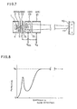
- Figure 1 shows sectional view along the axis showing configuration of a bipotential type electron gun of prior-art
- Figure 2 is a graph showing potential distribution along the axis of the electron gun.
- Thermal electrons emitted from the cathode 1 is focused by means of an electrostatic lens 4 called cathode lens which is constituted with a first grid (G1) as a control grid 2 and a second grid (G2) as an acceleration electrode 3, to produce a crossover 5, which is then preliminarily focused by a pre-focus lens 7 produced between the second grid (G2) 3 and the a third grid (G3) 6 as a focusing grid.
- the pro-focused electron beam is finally focused by a main lens 9 constituted with the third grid (G3) 6 and a fourth grid (G4) 8 as a final acceleration grid, thereby to produce a beam spot 11 on a fluorescent screen 10 by impinging thereto. That is, the beam spot 11 is an image of the crossover 5 projected by the pre-focus lens 7 and the main lens 9.
- the potential gradually rises from the cathode 1 to the rear end (inlet end) of the third grid (G3) 6, thereby forming the cathode lens 4 and the pre-focus lens 7.
- the cathode lens 4 and the pre-focus lens 7 can not be clearly distinguished, hereinafter these two lenses together are comprehensively called a beam forming part.
- the axial distribution in the third grid (G3) 6 is substantially constant at a value of V foc , thereafter the axial potential distribution rapidly rises from the outlet end of the third grid (G3) 6 to the fourth grid (G4) 8 to a high potential V a , thereby forming the main lens 9.
- the actual beam spot 11 projected on the fluorescent screen 10 by the main lens 9 is the image of virtual image of the crossover 5 having a diameter d.
- This virtual image of the crossover 5 can be obtained by extending the straight line part of the electron beam paths 12-17 towards the direction of the cathode 1. The crossing part of the straight lines gives the location of the virtual image.
- the diameter d s of the beam spot 11 on the fluorescent screen 10 is represented by the following equation (1).
- magnification M is represented by the following equation (2). wherein:
- the value of the bracketted part is determined by the size and operation conditions of the cathode ray tube and C s is determined by the diameter of lens used.
- the beam diameter D exists in the form of D- 1 in the leftest part of the right side, and in the form of D 3 in the rightest part, accordingly there is a value that will make d s minimum, and usually such value is selected. Under such condition, when d s is intended to be small, it is necessary to decrease a-do as small as possible.
- FIG. 4 is a graph showing relations between the gap between the second grid (G2) and the third grid (G3) versus the values a - do, a and do as such.
- the gap between the second grid (G2) and third grid (G3) is decreased, do drastically decreases and a increases contrarily, but as a result, a-do decreases.
- the reason that do drastically decreases as shown in Figure 4 is regarded as owing to peripheral aberration at the beam forming part decreases as the potential gradation increases.
- the practically admissible value of the potential gradient has an upper limit which is, according to the inventor's experiments, about 5x10 5 V/cm. Accordingly, when potential difference between the second grid (G2) and the third grid (G3) is selected 8 KV, taking account the above-mentioned admissible potential gradient, the gap between the second grid (G2) and the third grid (G3) becomes 0.8 mm to 0.16 mm.
- the diameter of the beam spot on the fluorescent screen can not be decreased as desired.
- the beam divergence angle a increases when the potential gradient between the second grid (G2) and the third grid (G3) is raised.
- the beam divergence angle a increases, diameter D of the electron beam in the main lens 9 increases, thereby undesirably increasing such part of the rightest part of the equation (3) which is influenced by the aberration of the main lens 9. Since the leftest part is proportional to third power of D, even a small increase of the diameter D of the electron beam prominently increases the rightest part. Accordingly, even though the value a.d o in the first term of the right side of the equation (3) decreases, the diameter d s of the beam spot on the fluorescent screen increases, on the contrary.
- the decrease of the beam diameter D of the electron beam can be prevented by decreasing length of the third grid (G3), but then it becomes necessary that the focal length of the main lens 9 must be shortened in order to satisfy the focusing condition. Accordingly, the potential of the third grid (G3) must be lowered. Such lowering of the third grid potential decreases potential gradient between the second grid (G2) and the third grid (G3), thereby wastly diminishing the effect of decrease of a-do in spite of decreasing the gap between the second grid (G2) and the third grid (G3).
- the present invention intends to dissolve the above-mentioned problems and eliminates the above-mentioned shortcomings of the conventional cathode ray tube, to provide an improved cathode ray tube having uniform small diameter of beam spot even for a wide range of brightness from a low brightness range to a high brightness range of operation.
- the cathode ray apparatus in accordance with the present invention comprises an electron gun, a fluorescent screen and an evacuated enclosure enclosing the electron gun and the fluorescent screen therein,
- the cathode ray tube of the present invention by increasing potential graduation at the beam forming part, spherical aberration as well as the diameter of virtual crossover can be decreased, and focal length of the main lens is shortened by adoption of a novel potential gradient profile in the main lens part formed by a third grid (G3), a fourth grid (G4) and a fifth grid (G5), thereby enabling to limit the diameter of the electron beam in the part of the main lens even under an increase of the beam divergence angle.
- This invention attains smallness of diameter of the beam spot on the fluorescent screen even when a large beam current flows for high brightness, thereby attaining high resolution characteristic.
- FIG. 5 shows a first embodiment wherein the electron gun comprises a first grid (G1) 2, a second grid (G2) 3, a third grid (G3) 22, a fourth grid (G4) 23 and a fifth grid (G5) 21, in this order from the cathode side to the fluorescent screen side.
- the first grid (G1) 2 works as a known control grid
- the second grid (G2) 3 has the same configuration as a known acceleration grid
- a third grid (G3) 22 is shaped a bored disk and is disposed close to the second grid (G2) 3 in order to make a large potential gradient of 10 5 V/cm-5x10 5 V/cm.
- the fourth grid (G4) 23 and the fifth grid (G5) 21 are both in simple cylindrical shape, and the third grid (G3) 22 is impressed with a constant voltage Vg 3 of +10 KV, and the fourth grid (G4) 23 is impressed with a variable focus voltage V foc which is lower than the constant voltage V .3 , and the fifth grid (G5) 21 is impressed with a positive high voltage V a of about 30 KV.
- the axial potential distribution in the fouth grid (G4) 23 is lower than the constant potential Vg 3 of the third grid (G3) 22, therefore the focal length of the main lens 25 is reduced in comparison with the conventional electron gun configuration. From the above-mentioned configuration, even with retaining the potential rise in the beamforming-part very steep, mutual distance between the virtual image crossover and the main lens can be shortened, thereby enabling the diameter of diverged beam at the part of the main lens 25 to decrease even when the beam divergence angle a increases. In view of the equation (3), this means that the value a.d o can be decreased without increase of the diverged beam diameter, and therefore the beam spot diameter d s can be decreased.
- FIG. 7 a second preferred embodiment is described with reference to Figure 7 and Figure 8.
- the mechanical configurations and their relative arrangements are substantially equal to the first embodiment of Figure 5 and Figure 6, but their potential distribution profile is modified. That is, the third grid (G3) 22 is electrically connected to the fifth grid (G5) 21, and the second grid (G2) 3 is impressed with a constant voltage so as to produce a potential gradient of 10 5 V/cm-5xlO 5 V/cm.
- the substantially cylindrical fourth grid (G4) 23 is impressed with a variable potential V foc , variable from almost 0 V to several KV.
- the fifth grid (G5) 21 is impressed with a constant potential of about 30 KV.
- the third grid (G3) 22 and the fifth grid (G5) 21 are impressed with high potentials, and the fourth grid (G4) 23 is impressed with a lower potential of several KV or lower, so that the potential distribution profile as shown in Figure 8 is produced.
- the fourth grid (G4) 23 and the fifth grid (G5) 21 are drawn to have substantially the same diameter, these may be of different diameters. Especially when the variable potential V foc is used at a voltage near 0 volt, the diameter of the fourth grid (G4) 23 should be preferably larger than the diameter of the fifth grid (G5) 21.
- axial potential distribution in the fourth grid (G4) 23 can be lower than the potential of the third grid (G3) 22 of the potential V 93 , accordingly, the focal distance can be shortened. Furthermore, since the electron gun can be shortened, the overall cathode ray tube length can be shortened.
- Fig. 9 shows a third embodiment.
- the components corresponding to the first embodiment of Figure 5 are designated by the corresponding numerals as marks, and their redundant superposed descriptions are omitted for simplicity.
- the principal difference of the third embodiment of Figure 9 from the first embodiment of Figure 5 is that between the fourth grid (G4) 23 and the fifth grid (G5) 21, an auxiliary grid (G4.5) 26 is added.
- the fourth grid (G4) 23, the auxiliary grid (G4.5) 26 and the fifth grid (G5) 21 are equally cylindrical-shaped, and the third grid (G3) 22 and the auxiliary grid (G4.5) 26 are each other electrically connected in the cathode ray tube, and they are to be impressed with a focusing potential V foc of about 6 KV-10 KV.
- the fourth grid (G4) 23 is impressed with a potential Vg 4 which is lower than the focusing potential V foc
- the fifth grid (G5) 21 is impressed with a high potential V a of about 30 KV.
- the axial potential of the fourth grid (G4) 23 is lower than the focusing potential V foc , and therefore the main lens 27 has a shorter focal distance in comparison with the conventional electron gun configuration.
- the thick main lens 27 has electric field distribution which gently changes in a very broad range, the spherical aberration of the main lens is small, thereby making the aberration coefficient C . of the rightest term of the equation (3) very small, accordingly minimizing the diameter d s of tha beam spot.
Claims (5)
Applications Claiming Priority (6)
| Application Number | Priority Date | Filing Date | Title |
|---|---|---|---|
| JP23412982A JPS59123139A (ja) | 1982-12-29 | 1982-12-29 | 受像管装置 |
| JP234130/82 | 1982-12-29 | ||
| JP23413082A JPS59123140A (ja) | 1982-12-29 | 1982-12-29 | 受像管装置 |
| JP234129/82 | 1982-12-29 | ||
| JP12251483A JPS6014733A (ja) | 1983-07-05 | 1983-07-05 | 受像管装置 |
| JP122514/83 | 1983-07-05 |
Publications (2)
| Publication Number | Publication Date |
|---|---|
| EP0113113A1 EP0113113A1 (fr) | 1984-07-11 |
| EP0113113B1 true EP0113113B1 (fr) | 1987-09-16 |
Family
ID=27314467
Family Applications (1)
| Application Number | Title | Priority Date | Filing Date |
|---|---|---|---|
| EP19830113068 Expired EP0113113B1 (fr) | 1982-12-29 | 1983-12-23 | Tube à rayons cathodiques |
Country Status (2)
| Country | Link |
|---|---|
| EP (1) | EP0113113B1 (fr) |
| DE (1) | DE3373746D1 (fr) |
Families Citing this family (1)
| Publication number | Priority date | Publication date | Assignee | Title |
|---|---|---|---|---|
| GB8728481D0 (en) * | 1987-12-04 | 1988-04-27 | Rank Brimar Ltd | Electron gun |
Family Cites Families (5)
| Publication number | Priority date | Publication date | Assignee | Title |
|---|---|---|---|---|
| US2902623A (en) * | 1956-08-17 | 1959-09-01 | Rca Corp | Electron gun structure |
| US2971108A (en) * | 1958-09-26 | 1961-02-07 | Sylvania Electric Prod | Electron discharge device |
| US3036238A (en) * | 1960-04-29 | 1962-05-22 | Sylvania Electric Prod | High resolution c.r. tube |
| DE2850656C2 (de) * | 1977-11-22 | 1984-04-19 | Tokyo Shibaura Denki K.K., Kawasaki, Kanagawa | Elektronenstrahlerzeugungssystem für Kathodenstrahlröhren |
| US4334170A (en) * | 1979-09-28 | 1982-06-08 | Zenith Radio Corporation | Means and method for providing optimum resolution of T.V. cathode ray tube electron guns |
-
1983
- 1983-12-23 DE DE8383113068T patent/DE3373746D1/de not_active Expired
- 1983-12-23 EP EP19830113068 patent/EP0113113B1/fr not_active Expired
Also Published As
| Publication number | Publication date |
|---|---|
| DE3373746D1 (en) | 1987-10-22 |
| EP0113113A1 (fr) | 1984-07-11 |
Similar Documents
| Publication | Publication Date | Title |
|---|---|---|
| EP0126486B1 (fr) | Canon à électrons pour tube d'image en couleurs | |
| US4427917A (en) | Television camera tube with electrostatic focusing | |
| EP0113113B1 (fr) | Tube à rayons cathodiques | |
| US4276495A (en) | Electron gun for cathode-ray tube | |
| US4368405A (en) | Electron gun for a cathode ray tube | |
| EP0081839B1 (fr) | Lentille de focalisation d'un faisceau d'électrons | |
| US4885505A (en) | Electron gun assembly | |
| US6819038B2 (en) | Double dynamic focus electron gun | |
| EP0031679B1 (fr) | Tube de caméra du type "vidicon" | |
| GB2145874A (en) | Cathode ray tubes | |
| US4201933A (en) | Electron gun structure for a pickup tube | |
| KR930009465B1 (ko) | 음극선관용 전자총 | |
| KR900009078B1 (ko) | 전자총 | |
| KR100719526B1 (ko) | 칼라 음극선관용 전자총 | |
| EP0027037A2 (fr) | Tube de caméra de télévision à focalisation électrostatique et déviation magnétique | |
| KR940010985B1 (ko) | 칼라 음극선관용 전자총 | |
| JPH0161220B2 (fr) | ||
| KR910005089B1 (ko) | 다단집속형 전자총 | |
| JPH0132622B2 (fr) | ||
| JPH0158823B2 (fr) | ||
| JPH0253905B2 (fr) | ||
| KR830000279B1 (ko) | 수상관용 전자총(受像管用 電子銃) | |
| JPH0419661B2 (fr) | ||
| KR910003949Y1 (ko) | 다단접속형 음극선관용 전자총 | |
| JPH0415977B2 (fr) |
Legal Events
| Date | Code | Title | Description |
|---|---|---|---|
| PUAI | Public reference made under article 153(3) epc to a published international application that has entered the european phase |
Free format text: ORIGINAL CODE: 0009012 |
|
| AK | Designated contracting states |
Designated state(s): DE GB |
|
| 17P | Request for examination filed |
Effective date: 19841029 |
|
| 17Q | First examination report despatched |
Effective date: 19860116 |
|
| GRAA | (expected) grant |
Free format text: ORIGINAL CODE: 0009210 |
|
| AK | Designated contracting states |
Kind code of ref document: B1 Designated state(s): DE GB |
|
| REF | Corresponds to: |
Ref document number: 3373746 Country of ref document: DE Date of ref document: 19871022 |
|
| PLBE | No opposition filed within time limit |
Free format text: ORIGINAL CODE: 0009261 |
|
| STAA | Information on the status of an ep patent application or granted ep patent |
Free format text: STATUS: NO OPPOSITION FILED WITHIN TIME LIMIT |
|
| 26N | No opposition filed | ||
| REG | Reference to a national code |
Ref country code: GB Ref legal event code: 746 Effective date: 19960819 |
|
| REG | Reference to a national code |
Ref country code: GB Ref legal event code: IF02 |
|
| REG | Reference to a national code |
Ref country code: GB Ref legal event code: 732E |
|
| PGFP | Annual fee paid to national office [announced via postgrant information from national office to epo] |
Ref country code: GB Payment date: 20021218 Year of fee payment: 20 |
|
| PGFP | Annual fee paid to national office [announced via postgrant information from national office to epo] |
Ref country code: DE Payment date: 20021231 Year of fee payment: 20 |
|
| PG25 | Lapsed in a contracting state [announced via postgrant information from national office to epo] |
Ref country code: GB Free format text: LAPSE BECAUSE OF EXPIRATION OF PROTECTION Effective date: 20031222 |
|
| REG | Reference to a national code |
Ref country code: GB Ref legal event code: PE20 |