EP0113031B1 - Apparatus for testing the purity of noble metal shaped bodies - Google Patents
Apparatus for testing the purity of noble metal shaped bodies Download PDFInfo
- Publication number
- EP0113031B1 EP0113031B1 EP83111752A EP83111752A EP0113031B1 EP 0113031 B1 EP0113031 B1 EP 0113031B1 EP 83111752 A EP83111752 A EP 83111752A EP 83111752 A EP83111752 A EP 83111752A EP 0113031 B1 EP0113031 B1 EP 0113031B1
- Authority
- EP
- European Patent Office
- Prior art keywords
- vibration
- moulding
- noble metal
- tested
- testing
- Prior art date
- Legal status (The legal status is an assumption and is not a legal conclusion. Google has not performed a legal analysis and makes no representation as to the accuracy of the status listed.)
- Expired
Links
Images


Classifications
-
- G—PHYSICS
- G01—MEASURING; TESTING
- G01N—INVESTIGATING OR ANALYSING MATERIALS BY DETERMINING THEIR CHEMICAL OR PHYSICAL PROPERTIES
- G01N29/00—Investigating or analysing materials by the use of ultrasonic, sonic or infrasonic waves; Visualisation of the interior of objects by transmitting ultrasonic or sonic waves through the object
- G01N29/04—Analysing solids
- G01N29/12—Analysing solids by measuring frequency or resonance of acoustic waves
-
- G—PHYSICS
- G01—MEASURING; TESTING
- G01H—MEASUREMENT OF MECHANICAL VIBRATIONS OR ULTRASONIC, SONIC OR INFRASONIC WAVES
- G01H13/00—Measuring resonant frequency
-
- G—PHYSICS
- G07—CHECKING-DEVICES
- G07D—HANDLING OF COINS OR VALUABLE PAPERS, e.g. TESTING, SORTING BY DENOMINATIONS, COUNTING, DISPENSING, CHANGING OR DEPOSITING
- G07D5/00—Testing specially adapted to determine the identity or genuineness of coins, e.g. for segregating coins which are unacceptable or alien to a currency
-
- G—PHYSICS
- G01—MEASURING; TESTING
- G01N—INVESTIGATING OR ANALYSING MATERIALS BY DETERMINING THEIR CHEMICAL OR PHYSICAL PROPERTIES
- G01N2291/00—Indexing codes associated with group G01N29/00
- G01N2291/02—Indexing codes associated with the analysed material
- G01N2291/028—Material parameters
- G01N2291/02854—Length, thickness
Definitions
- the invention relates to a device for checking the authenticity of precious metal moldings, in particular of precious metal ingots and precious metal blanks, by exciting the precious metal moldings via a vibration generator with transverse vibrations and measuring the resonance frequency with the aid of a vibration sensor.
- Gold bars and gold coins are preferably to be checked for their authenticity, but the device can also be used for moldings made of other noble metals, such as silver or platinum metals.
- test devices that determine the thermal conductivity of the test specimen can only be used to a limited extent, since this measuring principle places extreme demands on the tolerances of the test specimen dimensions, so that only special types of gold bars can be checked with them.
- a device for detecting counterfeit coins is known, in which the coin is subjected to mechanical transverse waves via a loudspeaker and the resonance frequency of the coin is determined with a microphone.
- this device has the disadvantage that it is only suitable for coins and is complex and bulky due to the necessary additional devices. In addition, it does not work very precisely.
- test specimens are subjected to longitudinal vibrations, an air gap each having to be formed between the test specimen and the vibration transmitter or vibration detector.
- counterfeit gold-plated tungsten-based products should be easy to spot.
- vibration transmitters and vibration sensors are designed as piezoelectric transducers and are coupled directly to the test specimen and one or more supports are provided for the test specimen.
- test specimens of different dimensions can be examined for their composition over their entire volume without destruction and without test residues.
- Every elastic body can be excited to characteristic vibrations, whereby the forms of vibration are limited to fundamental and harmonics.
- these vibration frequencies depend on the dimensions, the modulus of elasticity E and the density p of the test specimen. Lying e.g. rod-shaped body on two cutting edges, so they can perform transverse bending vibrations if they are deflected from their rest position by an external force.
- the frequency of the fundamental vibration of a rod depends on the thickness and length of the rod, the modulus of elasticity of its material and the density of the material. Does the external force with z. B.
- the body vibrates in resonance, i.e. with maximum vibration amplitudes. If various vibrations are applied to the body, the resonance frequency can be determined, which, given known dimensions, is a characteristic variable for the material of the molded body and can be used to identify it.
- Bars or blanks are preferably mounted on a flat plate made of elastic material or on two cutting edges or three support points and excited to transverse vibrations with a piezoelectric transducer, the frequency of which is continuously variable.
- the connection can be made using a thin wire with a diameter of around 1 mm, which is lightly pressed onto the test specimen or to which the test specimen is lightly pressed.
- the vibration amplitude is also measured with a piezoelectric transducer. Their maximum value indicates the resonance frequency, from which the ratio of modulus of elasticity / density can be read for known dimensions.
- the measurement result can be compared with a table value. Fakes are easy to spot, since there is no material or material combination that has the resonance frequency of fine gold. In particular, it is possible to identify tungsten inclusions in gold, which have the same density, but differ by a factor of 5 in the modulus of elasticity.
- the support is designed as a horizontal, flat plate made of an elastic material.
- This elastic plate must be larger than the possible test specimen, which is placed on the plate and lightly pressed against a needle-shaped vibrator attached to the edge of this plate.
- materials are used which allow the vibrations of the test specimens to be of the order of a few micrometers without significant hindrance. Felt, cork, velvet, velor fabrics, rubber and foamed plastics have proven to be suitable. Coarse-pore, foamed polyethylene with very low vibration damping values has proven particularly useful.
- the thickness of the elastic platen is not critical, but it should be greater than 1 mm.
- Test specimens of any shape and weight can be tested on this elastic pad, including any kind of precious metal bars and precious metal coins.
- electronic signals are generated or processed in the device.
- a vibrating test piece can be used to build a vibrating system, the frequency-determining element of which is the resonance frequencies of the test piece.
- the total gain must be greater than 1 and the phase shift equal to 0. This is achieved by amplifying the signal of the piezoelectric vibration sensor (possibly shifted in phase) and feeding it to the piezoelectric vibration sensor.
- This resonant circuit oscillates with a resonance frequency of the test specimen (self-excitation).
- the advantages of the self-excitation measuring circuit are the simple, inexpensive electronic structure. Testing with self-excitation, however, requires certain previous knowledge of the operating personnel, since depending on the location at which the vibration sensor is placed on the test specimen, harmonics can also develop in addition to the fundamental vibration. A discrete sequence of resonance frequencies can then be measured on the same test specimen, which makes it difficult for laypersons to interpret the measurement result.
- the oscillator signal is transmitted to the test specimen by the piezoelectric vibrator.
- the vibration frequency and vibration amplitude are measured and displayed using the vibration sensor. Since with continuous variation of the frequency of the oscillator successive fundamental and harmonics are displayed in resonance, the above-mentioned interpretation problems arise for the operating personnel. For simple handling, it is therefore desirable to store only one resonance frequency of a given test specimen at a time. This is achieved in that the oscillator emits certain characteristic frequencies that can be set and called up for characteristic test specimens (manufacturer, type, size, etc.). This makes the devices more user-friendly.
- Devices can also be used to test precious metal bars, in particular gold bars, in which the supports for the test specimen are designed as cutting edges, the position of which can be changed symmetrically to the center of the test specimen by means of a spindle.
- the supports for the test specimen are designed as cutting edges, the position of which can be changed symmetrically to the center of the test specimen by means of a spindle.
- two stops are also attached to a spindle, with the vibration sensor attached to one of the stops and a vibration sensor located above the center of the test specimen on a movable lever arm.
- the cutting edges and the stops preferably consist of polyacrylates.
- Devices for testing the authenticity of coin blanks made of precious metal can also be used, in which the test specimen rests on three radially displaceable supports designed as cones and the vibration transmitter and the vibration sensor are located together next to each other on a movable lever arm above the test center.
- the measurement of the resonance frequency takes place in the antinode of the oscillation which is formed, which is located in the center or on the edge of the round blank.
- the centering of the round blank is not problematic and can be done by eye.
- Figures I to IV schematically show some exemplary embodiments of devices for checking the authenticity of precious metal moldings
- Figure I representing a device with a flat support plate
- Figure II a device with two cutting edges as supports
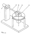
- Figure 111 a device with three tips as a support.
- Figure IV shows more details of the radial support shift.
- a device which can be used for bars, round blanks and other shaped bodies consists of a housing (28) into which the oscillator and the rest of the electronics are installed.
- the support (2) for receiving the test specimen (1) is designed as a flat plate and consists of an elastic material.
- the test specimen (1) is lightly pressed against the vibration transmitter (10), which is attached to the edge of the support (2) and protrudes into the air space above the support (2).
- the for commercially available shaped bodies (bars, coins) characteristic resonance frequencies can be entered into the oscillator using a keyboard (29).
- the vibration sensor (11) is removed from its holder and placed on the means of the test specimen (1).
- the maximum amplitude value of the frequency, ie the resonance frequency can be set precisely with a tuning button (30) and read off on a display window (31).
- a device is described in more detail with the aid of Figure II, with which bars of different dimensions can be tested.
- the bar In order for the basic vibration of the free bar to develop preferentially, the bar must be stored in the two nodes of the standing vibration, which according to physical laws are each 0.22 times the bar length from the center of the bar.
- the distance between the two supports (2) which have the shape of cutting edges, can be changed symmetrically to the center of the test using a spindle (5) with left and right-hand threads.
- the supports (2) are guided in bearings on two guide axes (7).
- Two stops (3, 4) which can also be moved symmetrically by a further spindle (6), are used to center the test specimen (1) with respect to the center of the distance between the two supports (2).
- Both spindles (5, 6) are driven by an actuator (8) with a reduction gear (9).
- the thread pitches of both spindles behave like 1 1.27, so that the distance between the support (2) and the stop (3 or 4) is always 0.22 x bar length.
- the stops (3, 4) are not used to clamp the test specimen (1), but as a centering aid when loading the device.
- the test specimen (1) and stops (3, 4) are separated by a fine gap so that the vibration is undamped. This gap is created by increasing the distance between the two stops (3, 4) immediately before the start of the measurement by turning the spindle (6) slightly backwards.
- the separation of the cutting edges is prevented by a freewheel on the threaded spindle (5), which only responds after the gearbox has been rotated backwards, for example by 120 °.
- the material from which the supports (2) and the stops (3, 4) are made must differ in their acoustic wave resistance of the test specimen in order to keep the transmission of vibrational energy of the ingot to the device structure as low as possible.
- the supports (2) and the stops (3, 4) are therefore preferably made of polyacrylic glass.
- the oscillation is excited laterally at a bar end by a vibration generator (10) which is mounted on a stop (4).
- Piezoelectric transducers which transmit a corresponding frequency range are suitable as vibration transmitters.
- a piezoelectric pickup is used, as is used in phono technology for scanning records. After unlocking a bar, the pickup is moved horizontally by spring force around a pivot point in the direction of the test specimen (1) in order to couple the head to the parallel bars.
- the vibration amplitude is determined in the middle of the bar by placing a lever arm (12) with a vibration sensor (11) on the test object (1).
- the lever arm (12) is provided with a counterweight (13) for adjusting the contact force.
- Any type of piezoelectric transducer is suitable for picking up vibrations.
- a piezoelectric accelerometer with a low weight is preferably used.
- the test process begins by entering the bar to be tested in an input keyboard.
- This input keyboard controls the servomotor (8) in such a way that the cutting edge distance corresponding to the respective bar type is set.
- the ingot is placed between the stops (3, 4) on the supports (2), the vibrator (10) is coupled by releasing the lock and the transducer (11) is placed on the ingot.
- the excitation frequency is varied in an interval with a frequency generator and the resonance frequency is determined. This measured value is compared with the target value, which is stored in the input unit for the corresponding bar types. In this way, any counterfeit can be recognized immediately.
- Figures 111 and IV schematically show a device for checking the authenticity of coin blanks.
- Vibration excitation and measurement of the vibration amplitude take place in the center of the test object (1).
- vibration sensor (15) and vibration sensor (16) are placed next to each other on the test object (18) on a lever arm (17).
- the contact force can be adjusted by means of a counterweight (19) on the lever arm (17).
- Piezoelectric pickups used as vibration transducers and piezoelectric vibration pickups for detecting the vibration amplitude.
- the coins are stored horizontally on three conical supports (20) which are embedded in a disk-shaped base plate (21).
- the base plate (21) contains three radially arranged elongated holes (22), each of which has an angle of 120 ° to one another.
- the supports (20) can be guided in these slots in the radial direction.
- This disc (23) contains spiral elongated holes (24) which extend from the center of the disc (23) to the edge thereof.
- a pin-like extension (25) of the supports (20) projects into each of these three spiral elongated holes (24).
- the supports (20) can be moved synchronously in the radial direction.
- coins of different diameters can be stored in the vibration node.
- the disk (23) is fixed and the base plate (21) is moved into the desired position by a stepper motor (26).
- the stepper motor (26) is mounted below both disks in the direction of the axis of rotation.
- the power is transmitted by a square nut (27) which snaps into the base plate (21).
- the functionality of the authenticity tester is demonstrated using the example of Krugerrand gold coins.
- the fundamental frequency of real coins is 9.1 kHz.
- Tungsten blanks of the same dimensions have resonance frequencies of 17.0 kHz. If tungsten blanks are coated with a gold layer of 200 ⁇ m, their resonance frequency drops to 16.1 kHz. The appearance of this coated modification is indistinguishable from real gold blanks, but the resonance frequencies are clearly separated. Further tests with blanks made of different light and heavy metals also show significant differences in the natural vibration frequencies. This demonstrates that the resonance frequency method is a meaningful authenticity check despite the relatively low expenditure on equipment.
Abstract
Description
Die Erfindung betrifft eine Vorrichtung zur Echtheitsprüfung von Edelmetallformkörpern, insbesondere von Edelmetallbarren und Edelmetallronden, durch Anregung der Edelmetallformkörper über einen Schwingungsgeber mit Transversalschwingungen und Messung der Resonanzfrequenz mit Hilfe eines Schwingungsaufnehmers. Bevorzugt sollen hiermit Goldbarren und Goldmünzen auf ihre Echtheit geprüft werden, jedoch ist die Vorrichtung auch auf Formkörper aus anderen Edelmetallen anwendbar, wie Silber oder Platinmetalle.The invention relates to a device for checking the authenticity of precious metal moldings, in particular of precious metal ingots and precious metal blanks, by exciting the precious metal moldings via a vibration generator with transverse vibrations and measuring the resonance frequency with the aid of a vibration sensor. Gold bars and gold coins are preferably to be checked for their authenticity, but the device can also be used for moldings made of other noble metals, such as silver or platinum metals.
Immer wieder werden Fälschungen von Goldbarren und Goldmünzen entdeckt, die entweder ganz aus unedleren Metallen bestehen oder bei denen ein Kern aus Unedelmetallen, insbesondere Blei oder Wolfram, nur mit einer dünnen Edelmetallschicht bedeckt ist. Solche Fälschungen bedeuten einen erheblichen materiallen Schaden und vermindern gleichzeitig das Vertrauen in Gold bzw. andere Edelmetalle als sichere Wertanlage.Forgeries of gold bars and gold coins are discovered again and again, which either consist entirely of base metals or in which a core of base metals, especially lead or tungsten, is only covered with a thin layer of precious metal. Such counterfeits mean considerable material damage and at the same time reduce trust in gold or other precious metals as a safe investment.
Es gibt daher Geräte, mit denen man beispielsweise bei Banken oder Juwelieren die Echtheit von Formkörpern bestimmter Abmessungen bestimmen kann und deren Messprinzip auf Methoden der zerstörungsfreien Materialprüfung beruht. Zur Materialidentifikation werden in der Praxis bisher Ultraschall- und Wirbelstromgeräte verwendet. Zur Ankoppelung des Ultraschallmesskopfes an den Prüfling muss bei den Ultraschallgeräten jedoch eine ölige Übertragungsflüssigkeit auf das Prüfobjekt aufgebracht werden, was kein sauberes Arbeiten gestattet. Ausserdem analysiert der Messkopf wegen seiner geringen Abmessungen normalerweise nur einen Teil des Prüflings. Ebenso messen Wirbelstromgeräte wegen der begrenzten Eindringtiefe von Hochfrequenz keine grösseren Probenvolumina aus. Auch Prüfgeräte, die die Wärmeleitfähigkeit des Prüflings bestimmen, sind nur begrenzt anwendbar, da bei diesem Messprinzip extreme Anforderungen an die Toleranzen der Prüflingsabmessungen gestellt sind, so dass nur spezielle Goldbarrentypen hiermit überprüft werden können. Aus der CH-PS 553 456 ist eine Vorrichtung zum Nachweis von gefälschten Münzen bekannt, bei der die Münze über einen Lautsprecher mit mechanischen Transversalwellen beaufschlagt wird und die Resonanzfrequenz der Münze mit einem Mikrophon bestimmt wird. Diese Vorrichtung hat aber den Nachteil, dass sie nur für Münzen geeignet ist und durch die notwendigen Zusatzgeräte aufwendig und voluminös gebaut ist. Ausserdem arbeitet sie nicht sehr genau.There are therefore devices that can be used, for example, to determine the authenticity of moldings of certain dimensions at banks or jewelers and whose measuring principle is based on methods of non-destructive material testing. In practice, ultrasound and eddy current devices have been used in practice for material identification. In order to connect the ultrasonic measuring head to the test specimen, however, an oily transmission fluid must be applied to the test object, which does not allow clean work. In addition, due to its small dimensions, the measuring head normally only analyzes a part of the test object. Eddy current devices also do not measure large sample volumes due to the limited penetration depth of high frequency. Even test devices that determine the thermal conductivity of the test specimen can only be used to a limited extent, since this measuring principle places extreme demands on the tolerances of the test specimen dimensions, so that only special types of gold bars can be checked with them. From CH-PS 553 456 a device for detecting counterfeit coins is known, in which the coin is subjected to mechanical transverse waves via a loudspeaker and the resonance frequency of the coin is determined with a microphone. However, this device has the disadvantage that it is only suitable for coins and is complex and bulky due to the necessary additional devices. In addition, it does not work very precisely.
Das gleiche gilt von einer Vorrichtung, wie sie in der GB-PS 1 011 472 beschrieben ist. Dort werden die Prüfkörper mit Längsschwingungen beaufschlagt, wobei zwischen Prüfkörper und Schwingungsgeber bzw. Schwingungsdetektor jeweils ein Luftspalt ausgebildet sein muss.The same applies to a device as described in GB-
Es war daher Aufgabe der vorliegenden Erfindung, eine Vorrichtung zur Echtheitsprüfung von Edelmetallformkörpern zu finden, insbesondere für Edelmetallbarren und Edelmetallronden, durch Anregung der Edelmetallformkörper über einen Schwingungsgeber mit Transversalschwingungen und Messung der Resonanzfrequenz mit Hilfe eines Schwingungsaufnehmers, die universell anwendbar ist, alle Formkörper prüfen kann, ein sauberes Arbeiten gestattet und einfach und handlich aufgebaut ist. Insbesondere sollten Fälschungen auf Wolframbasis mit Goldüberzug leicht erkennbar sein.It was therefore an object of the present invention to find a device for checking the authenticity of noble metal moldings, in particular for noble metal ingots and noble metal blanks, by exciting the noble metal moldings via a vibrator with transverse vibrations and measuring the resonance frequency with the aid of a vibration sensor, which can be used universally, can test all moldings , clean work is allowed and is simple and handy. In particular, counterfeit gold-plated tungsten-based products should be easy to spot.
Diese Aufgabe wurde erfindungsgemäss dadurch gelöst, dass Schwingungsgeber und Schwingungsaufnehmer als piezoelektrische Wandler ausgebildet und direkt an den Prüfkörper angekoppelt sind und eine oder mehrere Auflagen für den Prüfkörper vorhanden sind.This object has been achieved according to the invention in that vibration transmitters and vibration sensors are designed as piezoelectric transducers and are coupled directly to the test specimen and one or more supports are provided for the test specimen.
Mit dieser Vorrichtung können Prüflinge unterschiedlicher Abmessungen zerstörungsfrei und ohne Prüfrückstände über ihr gesamtes Volumen auf ihre Zusammensetzung untersucht werden. Jeder elastische Körper kann zu charakteristischen Schwingungen angeregt werden, wobei die Schwingungsformen auf Grundschwingung und Oberschwingungen beschränkt sind. Für eine vorgegebene Aufhängungsart bzw. Lagerung der Formkörper hängen diese Schwingungsfrequenzen von den Abmessungen, dem Elastizitätsmodul E und der Dichte p des Prüflings ab. Liegen z.B. stabförmige Körper auf zwei Schneiden auf, so können sie transversale Biegeschwingungen ausführen, falls sie durch eine äussere Kraft aus ihrer Ruhelage ausgelenkt werden. Die Frequenz der Grundschwingung eines Stabes ist nach bekannten Gleichungen abhängig von der Dicke und Länge des Stabes, dem Elastizitätsmodul seines Werkstoffs und der Dichte des Werkstoffs. Wirkt die äussere Kraft mit z. B. der Grundfrequenz auf den Körper ein, so schwingt der Körper in Resonanz, d.h. mit maximalen Schwingungsamplituden. Legt man verschiedene Schwingungen an den Körper an, lässt sich die Resonanzfrequenz bestimmen, die bei bekannten Abmessungen eine charakteristische Grösse für den Werkstoff des Formkörpers ist und zu dessen Identifizierung herangezogen werden kann.With this device, test specimens of different dimensions can be examined for their composition over their entire volume without destruction and without test residues. Every elastic body can be excited to characteristic vibrations, whereby the forms of vibration are limited to fundamental and harmonics. For a given type of suspension or storage of the moldings, these vibration frequencies depend on the dimensions, the modulus of elasticity E and the density p of the test specimen. Lying e.g. rod-shaped body on two cutting edges, so they can perform transverse bending vibrations if they are deflected from their rest position by an external force. According to known equations, the frequency of the fundamental vibration of a rod depends on the thickness and length of the rod, the modulus of elasticity of its material and the density of the material. Does the external force with z. B. the fundamental frequency on the body, the body vibrates in resonance, i.e. with maximum vibration amplitudes. If various vibrations are applied to the body, the resonance frequency can be determined, which, given known dimensions, is a characteristic variable for the material of the molded body and can be used to identify it.
Barren bzw. Ronden werden vorzugsweise auf eine aus elastischem Material bestehende, ebene Platte, oder auf zwei Schneiden bzw. drei Auflagepunkten gelagert und mit einem piezoelektrischen Wandler, dessen Frequenz kontinuierlich veränderlich ist, zu Transversalschwingungen angeregt. Die Ankoppelung kann über einen dünnen Draht mit einem Durchmesser von rund 1 mm erfolgen, der leicht an den Prüfling angedrückt wird bzw. an den der Prüfling leicht angedrückt wird. Die Schwingungsamplitude wird ebenfalls mit einem piezoelektrischen Wandler abgenommen. Ihr Maximalwert gibt die Resonanzfrequenz an, aus der bei bekannten Abmessungen das Verhältnis Elastizitätsmodul/Dichte abgelesen werden kann.Bars or blanks are preferably mounted on a flat plate made of elastic material or on two cutting edges or three support points and excited to transverse vibrations with a piezoelectric transducer, the frequency of which is continuously variable. The connection can be made using a thin wire with a diameter of around 1 mm, which is lightly pressed onto the test specimen or to which the test specimen is lightly pressed. The vibration amplitude is also measured with a piezoelectric transducer. Their maximum value indicates the resonance frequency, from which the ratio of modulus of elasticity / density can be read for known dimensions.
Da die Resonanzfrequenz für z. B. jeden Typ eines Feingoldbarrens charakteristisch ist, kann das Messergebnis mit einem Tabellenwert verglichen werden. Fälschungen sind leicht erkennbar, da es kein Material bzw. Materialkombination gibt, die die Resonanzfrequenz von Feingold besitzt. Insbesondere ist es möglich, Wolframeinschlüsse in Gold zu identifizierren, die zwar gleiche Dichte besitzen, aber im Elastizitätsmodul um den Faktor 5 sich unterscheiden.Since the resonance frequency for z. B. each type of fine gold ingot is characteristic, the measurement result can be compared with a table value. Fakes are easy to spot, since there is no material or material combination that has the resonance frequency of fine gold. In particular, it is possible to identify tungsten inclusions in gold, which have the same density, but differ by a factor of 5 in the modulus of elasticity.
Zur Prüfung der Edelmetallformkörper verwendet man vorzugsweise Vorrichtungen, bei denen die Auflage als horizontale, aus einem elastischen Material bestehende, ebene Platte ausgebildet ist. Diese elastische Platte muss grösser sein als der mögliche Prüfkörper, der auf die Platte aufgelegt und leicht gegen einen nadelförmigen Schwingungsgeber angedrückt wird, der am Rand dieser Platte angebracht ist. Für die elastische Platte verwendet man Werkstoffe, die Schwingungsauslenkungen der Prüfkörper, die in der Grössenordnung von einigen Mikrometern liegen können, ohne wesentliche Behinderung zulassen. Als geeignet haben sich Filz, Kork, Samt, Velourstoffe, Gummi und geschäumte Kunststoffe erwiesen. Besonders bewährt hat sich grobporiges, geschäumtes Polyäthylen mit sehr geringen Schwingungsdämpfungswerten. Die Dicke der elastischen Auflageplatte ist nicht entscheidend, sie sollte jedoch grösser als 1 mm sein.To test the precious metal moldings, devices are preferably used in which the support is designed as a horizontal, flat plate made of an elastic material. This elastic plate must be larger than the possible test specimen, which is placed on the plate and lightly pressed against a needle-shaped vibrator attached to the edge of this plate. For the elastic plate, materials are used which allow the vibrations of the test specimens to be of the order of a few micrometers without significant hindrance. Felt, cork, velvet, velor fabrics, rubber and foamed plastics have proven to be suitable. Coarse-pore, foamed polyethylene with very low vibration damping values has proven particularly useful. The thickness of the elastic platen is not critical, but it should be greater than 1 mm.
Auf dieser elastischen Auflage können Prüfkörper beliebiger Form und beliebigen Gewichts geprüft werden, also auch jede Art von Edelmetallbarren und Edelmetallmünzen.Test specimens of any shape and weight can be tested on this elastic pad, including any kind of precious metal bars and precious metal coins.
Zur Prüfung werden im Gerät elektronische Signale erzeugt bzw. verarbeitet. Es gibt zwei Ausführungsformen in der elektronischen Gerätefunktion: Erzeugung der zu beaufschlagenden Schwingungen durch den Probekörper selbst oder durch einen geräteinternen Frequenzgeber.For testing, electronic signals are generated or processed in the device. There are two embodiments in the electronic device function: generation of the vibrations to be applied by the test specimen itself or by an internal frequency transmitter.
Wie in einem elektrischen Schwingkreis, kann mit einem schwingenden Probekörper ein schwingendes System aufgebaut werden, dessen frequenzbestimmendes Element die Resonanzfrequenzen des Probekörpers sind. Dazu muss die Gesamtverstärkung grösser als 1 und die Phasenverschiebung gleich 0 sein. Man erreicht dies, indem das Signal des piezoelektrischen Schwingungsaufnehmers verstärkt (ggf. in der Phase verschoben) und dem piezoelektrischen Schwingungsgeber zugeführt wird. Dieser Schwingkreis oszilliert mit einer Resonanzfrequenz des Probekörpers (Selbsterregung).As in an electrical resonant circuit, a vibrating test piece can be used to build a vibrating system, the frequency-determining element of which is the resonance frequencies of the test piece. To do this, the total gain must be greater than 1 and the phase shift equal to 0. This is achieved by amplifying the signal of the piezoelectric vibration sensor (possibly shifted in phase) and feeding it to the piezoelectric vibration sensor. This resonant circuit oscillates with a resonance frequency of the test specimen (self-excitation).
Vorteile der Selbsterregermessschaltung sind der einfache, kostengünstige elektronische Aufbau. Die Prüfung mit Selbsterregung erfordert jedoch gewisse Vorkenntnisse des Bedienungspersonals, da sich in Abhängigkeit vom Ort, an dem der Schwingungsaufnehmer auf den Probekörper aufgesetzt wird, neben der Grundschwingung auch Oberschwingungen ausbilden können. An demselben Probekörper kann dann eine diskrete Folge von Resonanzfrequenzen gemessen werden, die die Interpretation des Messergebnisses für Laien erschwert.The advantages of the self-excitation measuring circuit are the simple, inexpensive electronic structure. Testing with self-excitation, however, requires certain previous knowledge of the operating personnel, since depending on the location at which the vibration sensor is placed on the test specimen, harmonics can also develop in addition to the fundamental vibration. A discrete sequence of resonance frequencies can then be measured on the same test specimen, which makes it difficult for laypersons to interpret the measurement result.
Es ist daher meist vorteilhaft, die zur Beaufschlagung der Probekörper notwendigen Frequenzen geräteintern von einem Oszillator zu erzeugen, der beliebige Frequenzen generieren kann. Das Oszillatorsignal wird durch den piezoelektrischen Schwingungsgeber auf den Probekörper übertragen. Mit dem Schwingungsaufnehmer wird Schwingungsfrequenz und Schwingungsamplitude gemessen und zur Anzeige gebracht. Da bei kontinuierlicher Variation der Frequenz des Oszillators nacheinander Grund- und Oberschwingungen in Resonanz angezeigt werden, ergeben sich auch hier die oben erwähnten Interpretationsprobleme für das Bedienungspersonal. Für eine einfache Handhabung ist es deshalb wünschenswert, jeweils nur eine Resonanzfrequenz eines gegebenen Prüflings einzuspeichern. Dies erreicht man dadurch, dass der Oszillator bestimmte charakteristische Frequenzen abgibt, die auf charakteristische Prüfkörper (Hersteller, Art, Grösse usw.) eingestellt und abrufbar sind. Dadurch lassen sich die Vorrichtungen bedienungsfreundlicher gestalten.It is therefore usually advantageous to generate the frequencies necessary for the application of the test specimen internally by an oscillator, which can generate any frequencies. The oscillator signal is transmitted to the test specimen by the piezoelectric vibrator. The vibration frequency and vibration amplitude are measured and displayed using the vibration sensor. Since with continuous variation of the frequency of the oscillator successive fundamental and harmonics are displayed in resonance, the above-mentioned interpretation problems arise for the operating personnel. For simple handling, it is therefore desirable to store only one resonance frequency of a given test specimen at a time. This is achieved in that the oscillator emits certain characteristic frequencies that can be set and called up for characteristic test specimens (manufacturer, type, size, etc.). This makes the devices more user-friendly.
Zur Prüfung von Edelmetallbarren, insbesondere Goldbarren, kann man auch Vorrichtungen verwenden, bei denen die Auflagen für den Prüfling als Schneiden ausgebildet sind, die mittels einer Spindel symmetrisch zur Prüflingsmitte in ihrer Lage verändert werden können. Zur Zentrierung des Prüflings sind zwei Anschläge ebenfalls auf einer Spindel befestigt, wobei an einem der Anschläge der Schwingungsgeber angebracht ist und über der Prüflingsmitte an einem beweglichen Hebelarm ein Schwingungsaufnehmer sich befindet. Vorzugsweise bestehen die Schneiden und die Anschläge aus Polyacrylaten.Devices can also be used to test precious metal bars, in particular gold bars, in which the supports for the test specimen are designed as cutting edges, the position of which can be changed symmetrically to the center of the test specimen by means of a spindle. To center the test specimen, two stops are also attached to a spindle, with the vibration sensor attached to one of the stops and a vibration sensor located above the center of the test specimen on a movable lever arm. The cutting edges and the stops preferably consist of polyacrylates.
Zur Echtheitsprüfung von Münzronden aus Edelmetall sind auch Vorrichtungen anwendbar, bei denen der Prüfling auf drei radial verschiebbaren, als Kegel ausgebildeten Auflagen aufliegt und der Schwingungsgeber und der Schwingungs- aufnehmer sich gemeinsam nebeneinander auf einem beweglichen Hebelarm über der Prüfungsmitte befinden. Die Messung der Resonanzfrequenz erfolgt dabei im Schwingungsbauch der sich ausbildenden Schwingung, der sich im Zentrum oder am Rand der Ronde befindet. Die Zentrierung der Ronde ist nicht problematisch und kann nach Augenmass durchgeführt werden.Devices for testing the authenticity of coin blanks made of precious metal can also be used, in which the test specimen rests on three radially displaceable supports designed as cones and the vibration transmitter and the vibration sensor are located together next to each other on a movable lever arm above the test center. The measurement of the resonance frequency takes place in the antinode of the oscillation which is formed, which is located in the center or on the edge of the round blank. The centering of the round blank is not problematic and can be done by eye.
Die Abbildungen I bis IV zeigen schematisch einige beispielhafte Ausführungsformen von Vorrichtungen zur Echtheitsprüfung von Edelmetallformkörpern, wobei Abbildung I eine Vorrichtung mit ebener Auflageplatte, Abbildung II eine Vorrichtung mit zwei Schneiden als Auflagen und Abbildung 111 eine Vorrichtung mit drei Spitzen als Auflage wiedergibt. Aus Abbildung IV sind nähere Einzelheiten der radialen Auflageverschiebung zu entnehmen.Figures I to IV schematically show some exemplary embodiments of devices for checking the authenticity of precious metal moldings, Figure I representing a device with a flat support plate, Figure II a device with two cutting edges as supports and Figure 111 a device with three tips as a support. Figure IV shows more details of the radial support shift.
Eine für Barren, Ronden und sonstige Formkörper verwendbare Vorrichtung besteht aus einem Gehäuse (28), in das der Oszillator und die übrige Elektronik eingebaut ist. Die Auflage (2) zur Aufnahme des Prüfkörpers (1) ist als ebene Platte ausgebildet und besteht aus einem elastischen Material. Der Prüfkörper (1) wird gegen den Schwingungsgeber (10) leicht angedrückt, der am Rande der Auflage (2) angebracht ist und in den Luftraum oberhalb der Auflage (2) hineinragt. Die für handelsübliche Formkörper (Barren, Münzen) charakteristischen Resonanzfrequenzen können über eine Tastatur (29) dem Oszillator eingegeben werden. Der Schwingungsaufnehmer (11) wird aus seiner Halterung entnommen und auf die Mittel des Prüfkörpers (1) aufgesetzt. Mit einem Abstimmknopf (30) lässt sich der maximale Amplitudenwert der Frequenz, d.h. die Resonanzfrequenz, genau einstellen und auf einem Anzeigefenster (31) ablesen.A device which can be used for bars, round blanks and other shaped bodies consists of a housing (28) into which the oscillator and the rest of the electronics are installed. The support (2) for receiving the test specimen (1) is designed as a flat plate and consists of an elastic material. The test specimen (1) is lightly pressed against the vibration transmitter (10), which is attached to the edge of the support (2) and protrudes into the air space above the support (2). The for commercially available shaped bodies (bars, coins) characteristic resonance frequencies can be entered into the oscillator using a keyboard (29). The vibration sensor (11) is removed from its holder and placed on the means of the test specimen (1). The maximum amplitude value of the frequency, ie the resonance frequency, can be set precisely with a tuning button (30) and read off on a display window (31).
Anhand der Abbildung II wird eine Vorrichtung näher beschrieben, mit der Barren verschiedener Abmessungen geprüft werden können. Damit sich die Grundschwingung des freien Barrens bevorzugt ausbilden kann, muss der Barren in den zwei Knoten der stehenden Schwingung gelagert werden, die nach physikalischen Gesetzen jeweils einen Abstand von 0,22 mal Barrenlänge von der Mitte des Barrens besitzen. Dazu kann der Abstand der beiden Auflagen (2), die die Form von Schneiden besitzen, über eine Spindel (5) mit Links- und Rechtsgewinde symmetrisch zur Prüfungsmitte verändert werden. Die Auflagen (2) werden in Lagern auf zwei Führungsachsen (7) geführt. Zur Zentrierung des Prüflings (1) bezüglich der Mitte des Abstands zwischen den beiden Auflagen (2) dienen zwei Anschläge (3, 4), die durch eine weitere Spindel (6) ebenfalls symmetrisch beweglich sind. Beide Spindeln (5, 6) werden von einem Stellmotor (8) mit Untersetzunggetriebe (9) angetrieben. Die Gewindesteigungen beider Spindeln verhalten sich wie 1 1,27, so dass der Abstand zwischen Auflage (2) und Anschlag (3 bzw. 4) stets 0,22 x Barrenlänge ist. Die Anschläge (3, 4) dienen nicht zur Einspannung des Prüflings (1), sondern als Zentrierungshilfe beim Beschicken des Gerätes. Während des Messvorganges sind Prüfling (1) und Anschläge (3, 4) durch einen feinen Spalt getrennt, damit sich die Schwingung ungedämpft ausbildet. Dieser Spalt wird erzeugt, indem unmittelbar vor Beginn der Messung der Abstand beider Anschläge (3, 4) durch ein geringes Rückwärtsdrehen der Spindel (6) vergrössert wird. Die Auseinanderbewegung der Schneiden wird durch einen Freilauf auf der Gewindespindel (5) verhindert, der erst nach einer Rückwärtsdrehung des Getriebes um beispielsweise 120° anspricht.A device is described in more detail with the aid of Figure II, with which bars of different dimensions can be tested. In order for the basic vibration of the free bar to develop preferentially, the bar must be stored in the two nodes of the standing vibration, which according to physical laws are each 0.22 times the bar length from the center of the bar. To do this, the distance between the two supports (2), which have the shape of cutting edges, can be changed symmetrically to the center of the test using a spindle (5) with left and right-hand threads. The supports (2) are guided in bearings on two guide axes (7). Two stops (3, 4), which can also be moved symmetrically by a further spindle (6), are used to center the test specimen (1) with respect to the center of the distance between the two supports (2). Both spindles (5, 6) are driven by an actuator (8) with a reduction gear (9). The thread pitches of both spindles behave like 1 1.27, so that the distance between the support (2) and the stop (3 or 4) is always 0.22 x bar length. The stops (3, 4) are not used to clamp the test specimen (1), but as a centering aid when loading the device. During the measurement process, the test specimen (1) and stops (3, 4) are separated by a fine gap so that the vibration is undamped. This gap is created by increasing the distance between the two stops (3, 4) immediately before the start of the measurement by turning the spindle (6) slightly backwards. The separation of the cutting edges is prevented by a freewheel on the threaded spindle (5), which only responds after the gearbox has been rotated backwards, for example by 120 °.
Das Material, aus dem die Auflagen (2) und die Anschläge (3, 4) hergestellt sind, muss sich in seinem Schallwellenwiderstand des Prüflings unterscheiden, um die Übertragung von Schwingungsenergie des Barrens auf die Gerätestruktur möglichst gering zu halten. Für Goldbarren sind deshalb die Auflagen (2) und die Anschläge (3, 4) vorzugsweise aus Polyacrylglas gefertigt.The material from which the supports (2) and the stops (3, 4) are made must differ in their acoustic wave resistance of the test specimen in order to keep the transmission of vibrational energy of the ingot to the device structure as low as possible. For gold bars, the supports (2) and the stops (3, 4) are therefore preferably made of polyacrylic glass.
Die Schwingungserregung erfolgt seitlich an einem Barrenende durch einen Schwingungsgeber (10), der auf einem Anschlag (4) montiert ist. Als Schwingungsgeber sind piezoelektrische Wandler geeignet, die einen entsprechenden Frequenzbereich übertragen. In der bevorzugten Ausführungsform wird ein piezoelektrischer Tonabnehmer verwendet, wie er in der Phonotechnik zur Abtastung von Schallplatten eingesetzt wird. Nach Entarretierung eines Riegels wird der Tonabnehmer durch Federkraft um einen Drehpunkt horizontal in Richtung des Prüflings (1) bewegt, um den Tonkopf an den Barren anzukoppetn.The oscillation is excited laterally at a bar end by a vibration generator (10) which is mounted on a stop (4). Piezoelectric transducers which transmit a corresponding frequency range are suitable as vibration transmitters. In the preferred embodiment, a piezoelectric pickup is used, as is used in phono technology for scanning records. After unlocking a bar, the pickup is moved horizontally by spring force around a pivot point in the direction of the test specimen (1) in order to couple the head to the parallel bars.
Die Schwingungsamplitude wird in der Barrenmitte bestimmt, indem ein Hebelarm (12) mit einem Schwingungsaufnehmer (11) auf den Prüfling (1) aufgelegt wird. Der Hebelarm (12) ist mit einem Ausgleichsgewicht (13) zur Einstellung der Auflagekraft versehen. Zur Schwingungsaufnahme ist jeder piezoelektrische Wandlertyp geeignet. Bevorzugt wird ein piezoelektrischer Beschleunigungsaufnehmer mit geringem Eigengewicht eingesetzt.The vibration amplitude is determined in the middle of the bar by placing a lever arm (12) with a vibration sensor (11) on the test object (1). The lever arm (12) is provided with a counterweight (13) for adjusting the contact force. Any type of piezoelectric transducer is suitable for picking up vibrations. A piezoelectric accelerometer with a low weight is preferably used.
Der Prüfprozess beginnt mit der Eingabe des zu prüfenden Barrens in eine Eingabetastatur. Diese Eingabetastatur steuert den Stellmotor (8) so, dass der dem jeweiligen Barrentyp entsprechende Schneidenabstand eingestellt wird. Der Barren wird zwischen die Anschläge (3, 4) auf die Auflagen (2) aufgelegt, der Schwingungsgeber (10) durch Lösen der Arretierung angekoppelt und der Aufnehmer (11) auf den Barren aufgesetzt. Die Erregerfrequenz wird mit einem Frequenzgenerator in einem Intervall variiert und die Resonanzfrequenz bestimmt. Dieser Messwert wird mit dem Sollwert, der in der Eingabeeinheit für die entsprechenden Barrentypen gespeichert ist, verglichen. Auf diese Weise lässt sich jede Fälschung sofort erkennen.The test process begins by entering the bar to be tested in an input keyboard. This input keyboard controls the servomotor (8) in such a way that the cutting edge distance corresponding to the respective bar type is set. The ingot is placed between the stops (3, 4) on the supports (2), the vibrator (10) is coupled by releasing the lock and the transducer (11) is placed on the ingot. The excitation frequency is varied in an interval with a frequency generator and the resonance frequency is determined. This measured value is compared with the target value, which is stored in the input unit for the corresponding bar types. In this way, any counterfeit can be recognized immediately.
An einem 100 g-Feingoldbarren wird die Funktionsfähigkeit dieses Prüfverfahrens demonstriert: es wird die Resonanzfrequenz 5,18 kHz gemessen. Barren gleicher Abmessungen, jedoch aus verschiedenen Metallen, sind durch eine abweichende Resonanzfrequenz zu identifizieren: f (AI) = 14,0 kHz, f (Cu) = 10,2 kHz, f (Pb) = 3,8 kHz, f (W) = 13,3 kHz. Gefälschte Feingoldbarren, die Einschlüsse aus Fremdmetallen enthalten, werden ebenfalls durch eine vom echten Barren abweichende Resonanzfrequenz erkannt.The functionality of this test method is demonstrated on a 100 g fine gold bar: the resonance frequency 5.18 kHz is measured. Bars of the same dimensions, but made of different metals, can be identified by a different resonance frequency: f (AI) = 14.0 kHz, f (Cu) = 10.2 kHz, f (Pb) = 3.8 kHz, f (W ) = 13.3 kHz. Fake fine gold bars that contain inclusions from foreign metals are also recognized by a resonance frequency that deviates from the real bar.
Die Abbildungen 111 und IV zeigen schematisch eine Vorrichtung zur Echtheitsprüfung von Münzronden.Figures 111 and IV schematically show a device for checking the authenticity of coin blanks.
Schwingungserregung und Messung der Schwingungsamplitude erfolgen im Zentrum des Prüflings (1). Dazu werden Schwingungsgeber (15) und Schwingungsaufnehmer (16) an einem Hebelarm (17) nebeneinander auf den Prüfling (18) aufgelegt. Die Auflagekraft ist durch ein Gegengewicht (19) am Hebelarm (17) einstellbar. Es werden z.B. piezoelektrische Tonabnehmer als Schwingungsgeber und piezoelektrische Schwingungsaufnehmer zur Erfassung der Schwingungsamplitude verwendet.Vibration excitation and measurement of the vibration amplitude take place in the center of the test object (1). For this purpose, vibration sensor (15) and vibration sensor (16) are placed next to each other on the test object (18) on a lever arm (17). The contact force can be adjusted by means of a counterweight (19) on the lever arm (17). E.g. Piezoelectric pickups used as vibration transducers and piezoelectric vibration pickups for detecting the vibration amplitude.
Mit dieser Vorrichtumg lassen sich Münzronden unterschiedlicher Grösse auf ihre Echtheit prüfen. Dazu werden die Münzen horizontal auf drei kegelförmigen Auflagen (20) gelagert, die in einer scheibenförmigen Grundplatte (21) eingelassen sind. Die Grundplatte (21) enthält drei radialförmig angeordnete Langlöcher (22), die jeweils einen Winkel von 120° zueinander haben. Die Auflagen (20) können in diesen Langlöchern geführt in radialer Richtung bewegt werden. Zur Veränderung der Radialpositionen der Auflagen (4) befindet sich eine weitere Scheibe (23) zentriert unterhalb der Grundplatte (21). Diese Scheibe (23) enthält spiralförmige Langlöcher (24), die sich vom Zentrum der Scheibe (23) zu deren Rand hin erstrekken. In jedes dieser drei spiralförmigen Langlöcher (24) ragt eine stiftartige Verlängerung (25) der Auflagen (20) hinein. Mit einer Drehung von Grundplatte (21) und Scheibe (23) relativ zueinander können die Auflagen (20) synchron in radialer Richtung bewegt werden. Mit dieser konstruktiven Auslegung lassen sich Münzen unterschiedlicher Durchmesser jeweils im Schwingungsknoten lagern. In einer bevorzugten Ausführungsform ist die Scheibe (23) fixiert, und die Grundplatte (21) wird durch einen Schrittmotor (26) in die gewünschte Stellung gefahren. Der Schrittmotor (26) ist unterhalb beider Scheiben in Richtung der Drehachse montiert. Die Kraftübertragung erfolgt durch eine Vierkantmutter (27), die in die Grundplatte (21) einrastet.With this device, coin blanks of different sizes can be checked for their authenticity. For this purpose, the coins are stored horizontally on three conical supports (20) which are embedded in a disk-shaped base plate (21). The base plate (21) contains three radially arranged elongated holes (22), each of which has an angle of 120 ° to one another. The supports (20) can be guided in these slots in the radial direction. To change the radial positions of the supports (4) there is another disc (23) centered below the base plate (21). This disc (23) contains spiral elongated holes (24) which extend from the center of the disc (23) to the edge thereof. A pin-like extension (25) of the supports (20) projects into each of these three spiral elongated holes (24). With a rotation of the base plate (21) and disc (23) relative to each other, the supports (20) can be moved synchronously in the radial direction. With this constructive design, coins of different diameters can be stored in the vibration node. In a preferred embodiment, the disk (23) is fixed and the base plate (21) is moved into the desired position by a stepper motor (26). The stepper motor (26) is mounted below both disks in the direction of the axis of rotation. The power is transmitted by a square nut (27) which snaps into the base plate (21).
Am Beispiel von Krugerrand-Goldmünzen wird die Funktionsfähigkeit des Echtheitsprüfgerätes demonstriert. Die Grundschwingungsfrequenz der echten Münzen ist 9,1 kHz. Wolframronden der gleichen Abmessungen haben Resonanzfrequenzen von 17,0 kHz. Werden Wolframronden mit einer Goldschicht von 200 um überzogen, sinkt ihre Resonanzfrequenz auf 16,1 kHz. Diese beschichtete Modifikation ist dem äusseren Anschein nach nicht von echten Goldronden zu unterscheiden, die Resonanzfrequenzen sind jedoch deutlich voneinander getrennt. Weitere Versuche mit Ronden aus verschiedenen Leicht- und Schwermetallen zeigen ebenfalls wesentliche Unterschiede der Eigenschwingungsfrequenzen. Damit ist demonstriert, dass die Resonanzfrequenzmethode trotz relativ geringen apparativen Aufwandes eine aussagekräftige Echtheitsprüfung ist.The functionality of the authenticity tester is demonstrated using the example of Krugerrand gold coins. The fundamental frequency of real coins is 9.1 kHz. Tungsten blanks of the same dimensions have resonance frequencies of 17.0 kHz. If tungsten blanks are coated with a gold layer of 200 µm, their resonance frequency drops to 16.1 kHz. The appearance of this coated modification is indistinguishable from real gold blanks, but the resonance frequencies are clearly separated. Further tests with blanks made of different light and heavy metals also show significant differences in the natural vibration frequencies. This demonstrates that the resonance frequency method is a meaningful authenticity check despite the relatively low expenditure on equipment.
Claims (4)
Priority Applications (1)
| Application Number | Priority Date | Filing Date | Title |
|---|---|---|---|
| AT83111752T ATE34232T1 (en) | 1982-12-03 | 1983-11-24 | DEVICE FOR TESTING THE AUTHENTICITY OF PRECIOUS METAL MOLDINGS. |
Applications Claiming Priority (2)
| Application Number | Priority Date | Filing Date | Title |
|---|---|---|---|
| DE3244717 | 1982-12-03 | ||
| DE3244717 | 1982-12-03 |
Publications (3)
| Publication Number | Publication Date |
|---|---|
| EP0113031A2 EP0113031A2 (en) | 1984-07-11 |
| EP0113031A3 EP0113031A3 (en) | 1985-04-10 |
| EP0113031B1 true EP0113031B1 (en) | 1988-05-11 |
Family
ID=6179689
Family Applications (1)
| Application Number | Title | Priority Date | Filing Date |
|---|---|---|---|
| EP83111752A Expired EP0113031B1 (en) | 1982-12-03 | 1983-11-24 | Apparatus for testing the purity of noble metal shaped bodies |
Country Status (7)
| Country | Link |
|---|---|
| EP (1) | EP0113031B1 (en) |
| JP (1) | JPS59150338A (en) |
| AT (1) | ATE34232T1 (en) |
| DE (1) | DE3376586D1 (en) |
| HK (1) | HK62590A (en) |
| IL (1) | IL70357A0 (en) |
| ZA (1) | ZA838869B (en) |
Families Citing this family (4)
| Publication number | Priority date | Publication date | Assignee | Title |
|---|---|---|---|---|
| DE4304170C2 (en) * | 1993-02-12 | 1995-10-19 | Isad Ingenieurbuero Gmbh Fuer | Method and device for recognizing surface structures |
| DE19908620C1 (en) * | 1999-02-27 | 2000-11-30 | Degussa | Device and method for checking the authenticity of shaped metal articles |
| GB2512289B (en) * | 2013-03-22 | 2018-12-26 | Ross Nedwell Jeremy | A device for determining the characteristic impedance spectrum of a token |
| FR3007141A1 (en) * | 2013-06-18 | 2014-12-19 | Jacques Clausin | DEVICE FOR CONTROLLING THE METALLURGICAL PURITY OF GOLD OBJECTS, ESPECIALLY INGOTS AND BARS |
Family Cites Families (6)
| Publication number | Priority date | Publication date | Assignee | Title |
|---|---|---|---|---|
| AT200364B (en) * | 1957-03-06 | 1958-10-25 | Horst Dipl Ing Kottas | Device for measuring the resonance frequencies of test specimens |
| GB1011472A (en) * | 1962-10-17 | 1965-12-01 | British Cast Iron Res Ass | Improvements in the non-destructive testing of materials |
| CH553456A (en) * | 1973-04-19 | 1974-08-30 | Kuniaki Miyazawa | COIN VALIDATOR. |
| DE2628178A1 (en) * | 1976-06-23 | 1977-12-29 | Cremer & Breuer Keramische | METHOD AND DEVICE FOR AUTOMATIC, CONTINUOUS, NON-DESTRUCTION-FREE QUALITY CONTROL, IN PARTICULAR OF STONE PIPES |
| DK139597B (en) * | 1977-07-01 | 1979-03-12 | Akad Tekn Videnskaber | Apparatus for recording echo impulses during ultrasound examinations. |
| JPS5734545A (en) * | 1980-08-08 | 1982-02-24 | Canon Inc | Camera |
-
1983
- 1983-11-24 AT AT83111752T patent/ATE34232T1/en not_active IP Right Cessation
- 1983-11-24 EP EP83111752A patent/EP0113031B1/en not_active Expired
- 1983-11-24 DE DE8383111752T patent/DE3376586D1/en not_active Expired
- 1983-11-28 ZA ZA838869A patent/ZA838869B/en unknown
- 1983-12-01 IL IL70357A patent/IL70357A0/en unknown
- 1983-12-02 JP JP58227100A patent/JPS59150338A/en active Pending
-
1990
- 1990-08-09 HK HK625/90A patent/HK62590A/en unknown
Non-Patent Citations (1)
| Title |
|---|
| Dtv-lexikon der Physik, Bd. 7, Seiten 80-83 * |
Also Published As
| Publication number | Publication date |
|---|---|
| JPS59150338A (en) | 1984-08-28 |
| DE3376586D1 (en) | 1988-06-16 |
| ATE34232T1 (en) | 1988-05-15 |
| EP0113031A3 (en) | 1985-04-10 |
| HK62590A (en) | 1990-08-17 |
| EP0113031A2 (en) | 1984-07-11 |
| ZA838869B (en) | 1984-12-24 |
| IL70357A0 (en) | 1984-03-30 |
Similar Documents
| Publication | Publication Date | Title |
|---|---|---|
| US5408882A (en) | Ultrasonic device and method for non-destructive evaluation of polymer composites | |
| EP0718596B1 (en) | Procedure and device to determine dynamically the thickness and/or the weight of a moving object | |
| EP0336224B1 (en) | Sensor and method for acoustic emission examination | |
| DE60014387T2 (en) | METHOD AND DEVICE FOR DETERMINING THE HARDENESS OF A PRODUCT SUCH AS FRUIT | |
| DE2844143A1 (en) | DEVICE FOR MEASURING THE DENSITY OF A LIQUID | |
| DE3045581A1 (en) | DEVICE FOR MEASURING THE SPEED OF SPREADING FROM A MOVING MATERIAL, IN PARTICULAR PAPER, THROUGH ULTRASOUND WAVES | |
| WO1991010131A1 (en) | Process for the acoustic examination of monoliths for damage and device for implementing the process | |
| DE2260932B2 (en) | Method for determining the depth of cracks in workpieces | |
| DE2049550A1 (en) | Test facility for vehicle suspensions | |
| EP0113031B1 (en) | Apparatus for testing the purity of noble metal shaped bodies | |
| CH422383A (en) | Impact testing device | |
| DE1648738B1 (en) | DEVICE FOR NON-DESTRUCTIVE MEASUREMENT OF THE STIFFNESS OF NON-METALLIC FLEXIBLE FLAT FORMS | |
| EP0763732B1 (en) | Device for the acoustic material inspection of molded articles | |
| DE3628313A1 (en) | LASER INDUCED ACOUSTIC GENERATION FOR SOUND MODULE | |
| DE2528575C3 (en) | ||
| DE3342418C2 (en) | Device for checking the authenticity of precious metal moldings | |
| DE19806905C2 (en) | Device for determining viscoelastic parameters of a solid or liquid substance | |
| EP0737861B1 (en) | Method and apparatus for non-destructive determination of properties of a metal component | |
| DE69922205T2 (en) | METHOD AND DEVICE FOR SURFACE TESTING | |
| EP1124125A2 (en) | Process and device for acoustic detection of microparticles | |
| DE3814172C2 (en) | ||
| EP0158929A2 (en) | Method for the ultrasonic testing of bolts with a jump in wall thickness | |
| DE1648738C (en) | Device for the non-destructive measurement of the stiffness of non-metallic, flexible, flat structures | |
| DE3308022C2 (en) | Reflection ultrasonic microscope | |
| DE2421429A1 (en) | Non-destructive material testing using ultrasonics - involves several send-receive units with different resonance surfaces in one housing |
Legal Events
| Date | Code | Title | Description |
|---|---|---|---|
| PUAI | Public reference made under article 153(3) epc to a published international application that has entered the european phase |
Free format text: ORIGINAL CODE: 0009012 |
|
| 17P | Request for examination filed |
Effective date: 19831124 |
|
| AK | Designated contracting states |
Designated state(s): AT BE CH DE FR GB IT LI LU NL SE |
|
| PUAL | Search report despatched |
Free format text: ORIGINAL CODE: 0009013 |
|
| AK | Designated contracting states |
Designated state(s): AT BE CH DE FR GB IT LI LU NL SE |
|
| 17Q | First examination report despatched |
Effective date: 19860801 |
|
| GRAA | (expected) grant |
Free format text: ORIGINAL CODE: 0009210 |
|
| AK | Designated contracting states |
Kind code of ref document: B1 Designated state(s): AT BE CH DE FR GB IT LI LU NL SE |
|
| REF | Corresponds to: |
Ref document number: 34232 Country of ref document: AT Date of ref document: 19880515 Kind code of ref document: T |
|
| ITF | It: translation for a ep patent filed |
Owner name: JACOBACCI & PERANI S.P.A. |
|
| GBT | Gb: translation of ep patent filed (gb section 77(6)(a)/1977) | ||
| REF | Corresponds to: |
Ref document number: 3376586 Country of ref document: DE Date of ref document: 19880616 |
|
| ET | Fr: translation filed | ||
| PLBE | No opposition filed within time limit |
Free format text: ORIGINAL CODE: 0009261 |
|
| STAA | Information on the status of an ep patent application or granted ep patent |
Free format text: STATUS: NO OPPOSITION FILED WITHIN TIME LIMIT |
|
| 26N | No opposition filed | ||
| ITTA | It: last paid annual fee | ||
| EPTA | Lu: last paid annual fee | ||
| EAL | Se: european patent in force in sweden |
Ref document number: 83111752.8 |
|
| PGFP | Annual fee paid to national office [announced via postgrant information from national office to epo] |
Ref country code: LU Payment date: 19951001 Year of fee payment: 13 |
|
| PGFP | Annual fee paid to national office [announced via postgrant information from national office to epo] |
Ref country code: SE Payment date: 19951011 Year of fee payment: 13 |
|
| PGFP | Annual fee paid to national office [announced via postgrant information from national office to epo] |
Ref country code: DE Payment date: 19951019 Year of fee payment: 13 |
|
| PGFP | Annual fee paid to national office [announced via postgrant information from national office to epo] |
Ref country code: BE Payment date: 19951024 Year of fee payment: 13 |
|
| PGFP | Annual fee paid to national office [announced via postgrant information from national office to epo] |
Ref country code: AT Payment date: 19951110 Year of fee payment: 13 |
|
| PGFP | Annual fee paid to national office [announced via postgrant information from national office to epo] |
Ref country code: GB Payment date: 19951115 Year of fee payment: 13 |
|
| PGFP | Annual fee paid to national office [announced via postgrant information from national office to epo] |
Ref country code: CH Payment date: 19951117 Year of fee payment: 13 |
|
| PGFP | Annual fee paid to national office [announced via postgrant information from national office to epo] |
Ref country code: NL Payment date: 19951130 Year of fee payment: 13 Ref country code: FR Payment date: 19951130 Year of fee payment: 13 |
|
| PG25 | Lapsed in a contracting state [announced via postgrant information from national office to epo] |
Ref country code: LU Free format text: LAPSE BECAUSE OF NON-PAYMENT OF DUE FEES Effective date: 19961124 Ref country code: GB Effective date: 19961124 Ref country code: AT Effective date: 19961124 |
|
| PG25 | Lapsed in a contracting state [announced via postgrant information from national office to epo] |
Ref country code: SE Effective date: 19961125 |
|
| PG25 | Lapsed in a contracting state [announced via postgrant information from national office to epo] |
Ref country code: LI Effective date: 19961130 Ref country code: CH Effective date: 19961130 Ref country code: BE Effective date: 19961130 |
|
| BERE | Be: lapsed |
Owner name: DEGUSSA A.G. Effective date: 19961130 |
|
| PG25 | Lapsed in a contracting state [announced via postgrant information from national office to epo] |
Ref country code: NL Effective date: 19970601 |
|
| REG | Reference to a national code |
Ref country code: CH Ref legal event code: PL |
|
| GBPC | Gb: european patent ceased through non-payment of renewal fee |
Effective date: 19961124 |
|
| PG25 | Lapsed in a contracting state [announced via postgrant information from national office to epo] |
Ref country code: FR Effective date: 19970731 |
|
| NLV4 | Nl: lapsed or anulled due to non-payment of the annual fee |
Effective date: 19970601 |
|
| PG25 | Lapsed in a contracting state [announced via postgrant information from national office to epo] |
Ref country code: DE Effective date: 19970801 |
|
| EUG | Se: european patent has lapsed |
Ref document number: 83111752.8 |
|
| REG | Reference to a national code |
Ref country code: FR Ref legal event code: ST |