EP0112977A1 - Shut-off device for aggressive fluids - Google Patents
Shut-off device for aggressive fluids Download PDFInfo
- Publication number
- EP0112977A1 EP0112977A1 EP83109799A EP83109799A EP0112977A1 EP 0112977 A1 EP0112977 A1 EP 0112977A1 EP 83109799 A EP83109799 A EP 83109799A EP 83109799 A EP83109799 A EP 83109799A EP 0112977 A1 EP0112977 A1 EP 0112977A1
- Authority
- EP
- European Patent Office
- Prior art keywords
- shut
- flow
- medium
- housing
- open position
- Prior art date
- Legal status (The legal status is an assumption and is not a legal conclusion. Google has not performed a legal analysis and makes no representation as to the accuracy of the status listed.)
- Withdrawn
Links
Images

Classifications
-
- F—MECHANICAL ENGINEERING; LIGHTING; HEATING; WEAPONS; BLASTING
- F16—ENGINEERING ELEMENTS AND UNITS; GENERAL MEASURES FOR PRODUCING AND MAINTAINING EFFECTIVE FUNCTIONING OF MACHINES OR INSTALLATIONS; THERMAL INSULATION IN GENERAL
- F16K—VALVES; TAPS; COCKS; ACTUATING-FLOATS; DEVICES FOR VENTING OR AERATING
- F16K5/00—Plug valves; Taps or cocks comprising only cut-off apparatus having at least one of the sealing faces shaped as a more or less complete surface of a solid of revolution, the opening and closing movement being predominantly rotary
- F16K5/06—Plug valves; Taps or cocks comprising only cut-off apparatus having at least one of the sealing faces shaped as a more or less complete surface of a solid of revolution, the opening and closing movement being predominantly rotary with plugs having spherical surfaces; Packings therefor
- F16K5/0605—Plug valves; Taps or cocks comprising only cut-off apparatus having at least one of the sealing faces shaped as a more or less complete surface of a solid of revolution, the opening and closing movement being predominantly rotary with plugs having spherical surfaces; Packings therefor with particular plug arrangements, e.g. particular shape or built-in means
Definitions
- the invention relates to a shut-off valve for aggressive media according to the preamble of patent claim 1.
- shut-off valves there is a design-related dead space between the shut-off element and the housing or the sealing rings fixed to the housing. In the open position, this dead space is not flushed out and the aggressive medium located in this dead space can polymerize, crystallize out or otherwise change its state in such a way that the shut-off element finally seizes on the housing during the transition from the open position to the closed position, and only with difficulty or not at all is movable. There is also the risk that the sealing rings fixed to the housing will be damaged when the shut-off element is closed.
- the object of the invention is to make such a shut-off valve more reliable in accordance with the preamble of claim 1.
- the invention is characterized in that in the open position of the shut-off element there is a secondary flow flowing parallel to the main flow and flushing through the dead space.
- the shut-off device is formed as ugelküken K and having on the outer circumference flattenings which assign in the open position, the dead space flow channels.
- the flats on the shut-off element described above are designed so that the outer circumference of the shut-off element is at a distance from the sealing rings fixed to the housing, and that due to this distance a secondary flow from the main flow of the medium can be generated, which flushes through the dead space.
- the upstream flushing channel is inclined towards the media flow with its mouth so that the medium enters this flushing channel under high pressure, while the downstream flushing channel is inclined is inclined in the opposite direction to the media flow, so that the flushing liquid is comparatively sucked out of this flushing channel.
- shut-off device is either a ball plug, a cone plug or a cylinder plug.
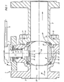
- a two-part housing 1 which consists of a main part 2 and an additional part 3.
- Main part 2 and supplementary part 3 are connected to one another via four connecting flange screws 10, with corresponding flange seals 11 being interposed.
- the main part 2 has a central recess at the top, into which the shaft 6 of an actuating element engages, the shaft 6 being connected at the top in a rotationally fixed manner to an actuating lever 4 via a fastening screw 5.
- a disc spring 7 is arranged in a central recess, which is closed by a cover 30, which presses via a metal ring 8 onto a sealing packing 9 arranged below it .
- a similar packing 9 is arranged on the underside of the shaft 6.
- a square 12 is milled, which is pressed upward via an axially spring-loaded pressure piece 13 in the direction of the arrow 14, the pressure piece 13 being arranged in a slot 16 of a ball plug 15.
- the ball plug 15 takes over the sealing between the inflow and outflow via the sealing rings 22, 23 to the housing 1.
- the ball plug 15 consists of an approximately spherical body which has a central through-hole 17 through which the medium flows in the direction of the arrow 18.
- An essential feature is that in the bypass to the main passage of the ball plug, a secondary passage is created, in which a secondary flow space 20 is present, through which the medium flow flows in the direction of arrow 21 when the ball plug is in the open position.
- This tributary space 20 extends approximately annularly around the entire ball plug 15.
- the medium therefore flows through it in the direction of the arrow 21 Tributary space, rinses it and leaves the tributary space in the direction of arrow 26, where this flow combines with the main flow in the direction of arrow 18.
- a relief bore 19 can be provided on the drain side in a further embodiment of the present invention.
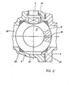
- FIG. 2 It can be seen that in the closed position of the ball plug 15, the central through bore 17 is closed off by the inflow channel 33, the ring seals 22, 23 sealingly abutting the outer circumference of the ball plug 15.
- the medium located in the through-hole 17 can now flow to the discharge side via the relief hole 19, and the lower and upper annular spaces 24 with the medium located there, which flows into the through-hole 17 via the outer circumference of the ball plug, are discharged via the through-hole 19 .
- a tributary space 20 is created in the open position, which thus prevents any dead spaces that are not flushed from being present in the open position.
- FIG. 7 shows a second embodiment of a fickle plug 25.
- the ball plug there corresponds in its shape more like a round ball compared to the embodiment according to FIGS. 1-6, both in the open position and in the closed position a sealing engagement of the sealing rings 22, 23 on the outer circumference of the ball plug 25 is always achieved.
- the medium flow entering in the direction of arrow 18 in turn flows through the through hole 27 and flows out to the drainage channel.
- annular space 34 which is closed per se, is formed, which lies between the sealing rings 22, 23.
- flushing channels 28, 29 are again provided, which preferably lead obliquely in the direction of the flow direction from the inflow channel 33 into the annular space 34.
- the medium thus enters the annular space in the direction of the arrow 31 and this annular space is flushed, after which the medium emerges from the flushed annular space 34 again in the direction of the arrow 32.
- An essential feature is therefore that dead spaces in closed and open positions are not always closed in a shut-off device of any shape, but rather have corresponding channels to the main flow, so that a constant flushing flow takes place into these otherwise existing dead spaces.
- the relief bore 19 can of course also be provided elsewhere and in a different direction.
- it can be arranged in such a way that a complete seepage of the medium present in the through bore 17 is possible in the direction of the drainage channel.
- the material of the ball plug 15.25 is arbitrary. It can be made of plastic or metal.
- flushing channels of the same type can also be provided upwards into the upper annular space 34, which results in an improved flushing effect, although this is not necessary because the annular space 34 is in flow connection at the top and bottom.
Abstract
Description
Die Erfindung betrifft eine Absperrarmatur für aggressive Medien nach dem Oberbegriff des Patentanspruchs 1.The invention relates to a shut-off valve for aggressive media according to the preamble of patent claim 1.
Bei derartigen Absperrarmaturen besteht ein konstruktiv bedingter Totraum zwischen dem Absperrorgan und dem Gehäuse bzw. den gehäusefesten Dichtringen. In Offenstellung wird dieser Totraum nicht durchspült und das in diesem Totraum befindliche aggressive Medium kann Polymerisieren, Auskristallisieren oder sonstwie seinen Zustand derart ändern, daß das Absperrorgan schließlich beim Übergang von der Offenstellung in die Schließstellung am Gehäuse festfrisst, und nur noch schwer oder überhaupt nicht mehr bewegbar ist. Hierbei besteht auch die Gefahr, daß die gehäusefesten Dichtringe beim Schließen des Absperrorgans beschädigt werden.In such shut-off valves there is a design-related dead space between the shut-off element and the housing or the sealing rings fixed to the housing. In the open position, this dead space is not flushed out and the aggressive medium located in this dead space can polymerize, crystallize out or otherwise change its state in such a way that the shut-off element finally seizes on the housing during the transition from the open position to the closed position, and only with difficulty or not at all is movable. There is also the risk that the sealing rings fixed to the housing will be damaged when the shut-off element is closed.
Aufgabe der Erfindung ist es, eine derartige Absperrarmatur nach dem Oberbegriff des Anspruchs 1 betriebssicherer zu gestalten.The object of the invention is to make such a shut-off valve more reliable in accordance with the preamble of claim 1.
Zur Lösung der gestellten Aufgabe ist die Erfindung dadurch gekennzeichnet, daß in der Offenstellung des Absperrorgans ein parallel zum Hauptfluß fliessender, den Totraum durchspülender Nebenfluß vorhanden ist.To achieve the object, the invention is characterized in that in the open position of the shut-off element there is a secondary flow flowing parallel to the main flow and flushing through the dead space.
Mit der Durchspülung des Totraumes in Offenstellung wird also eine Ablagerung des Mediums im Totraum verhindert und damit wird das gefürchtete Festfressen des Absperrorgans vermieden. Um ein Festfressen auch in Schließstellung zu vermeiden, ist es bekannt, entsprechende Entlastungsbohrungen im Absperrorgan vorzusehen, damit das im Absperrorgan noch befindliche Medium zur Abflußseite hin abfließen kann.By flushing the dead space in the open position, a deposition of the medium in the dead space is prevented and the feared seizure of the shut-off element is avoided. To seize too To avoid in the closed position, it is known to provide appropriate relief bores in the shut-off device so that the medium still in the shut-off device can flow off to the outflow side.
Man kann die konstruktive Ausbildung der vom Medium durchflossenen Toträume so gestalten, daß sie nur in einer bestimmten Offenstellung des Absperrorgans durchflossen werden, während sie beispielsweise bei noch nicht voll erreichter Offenstellung nicht durchflossen sind.One can design the constructive design of the dead spaces through which the medium flows so that they flow through only in a certain open position of the shut-off element, while for example when they are not yet fully open, they do not flow through.
Bei einer bevorzugten Ausführungsform der vorliegenden Erfindung ist es vorgesehen, daß das Absperrorgan als Kugelküken ausgebildet ist und am Aussenumfang Abflachungen aufweist, die in der Offenstellung dem Totraum Durchflußkanäle zuordnen.In a preferred embodiment of the present invention, it is provided that the shut-off device is formed as ugelküken K and having on the outer circumference flattenings which assign in the open position, the dead space flow channels.
In Offenstellung wird also stets im Bypass zum Hauptfluß des Mediums ein Nebenfluß durch den sonst vorhandenen Totraum erzeugt.In the open position, a bypass to the main flow of the medium is always generated as a tributary through the otherwise existing dead space.
Es gelingt also auf besonders einfache und kostengünstige Weise, eine solche Absperrarmatur wesentlich betriebssicherer zu gestalten. Statt der Ausbildung von Abflachungen am Kugelküken kann man auch von außen mit irgendeinem Spülsystem den Totraum durchströmen lassen.It is thus possible in a particularly simple and inexpensive way to make such a shut-off valve considerably more reliable. Instead of the formation of flats on the ball plug, you can also flow through the dead space from the outside with some flushing system.
Die vorher beschriebenen Abflachungen am Absperrorgan sind so ausgebildet, daß das Absperrorgan mit seinem Außenumfang von den gehäusefesten Dichtringen einen Abstand aufweist, und daß durch diesen Abstand bedingt ein Nebenfluß vom Hauptfluß des Mediums erzeugbar ist, welcher den Totraum durchspült.The flats on the shut-off element described above are designed so that the outer circumference of the shut-off element is at a distance from the sealing rings fixed to the housing, and that due to this distance a secondary flow from the main flow of the medium can be generated, which flushes through the dead space.
In einer anderen Ausführungsform der iorliegenden Erfindung ist es vorgesehen, daß in der Offenstellung das Absperrorgan mit seinem Außenumfang dichtend an den gehäusefesten Dichtringen anliegt, wobei von der zentralen Durchgangsbohrung des Absperrorgans ausgehende, in den Totraum mündende Spülkanäle vorgesehen sind.In another embodiment of the present invention, it is provided that in the open position The outer circumference of the shut-off element lies sealingly on the sealing rings fixed to the housing, flushing channels opening out from the central through-hole of the shut-off element opening into the dead space being provided.
Um den Durchfluß durch den sonst vorhandenen Totraum zu verbessern, ist es vorgesehen, daß der stromaufwärts gelegene Spülkanal schräg in Richtung zum Medienstrom hin mit seiner Mündung geneigt ist, so daß das Medium unter hohem Druck in diesen Spülkanal eintritt, während der stromabwärts gelegene Spülkanal schräg in Gegenrichtung zur Medienströmung geneigt ist, so daß aus diesem Spülkanal vergleichsweise die Spülflüssigkeit abgesaugt wird.In order to improve the flow through the otherwise existing dead space, it is provided that the upstream flushing channel is inclined towards the media flow with its mouth so that the medium enters this flushing channel under high pressure, while the downstream flushing channel is inclined is inclined in the opposite direction to the media flow, so that the flushing liquid is comparatively sucked out of this flushing channel.
Es liegt im Rahmen der vorliegenden Erfindung, daß das Absperrorgan entweder ein Kugelküken, ein Kegelküken oder ein Zylinderküken ist.It is within the scope of the present invention that the shut-off device is either a ball plug, a cone plug or a cylinder plug.
Der Erfindungsgegenstand der vorliegenden Erfindung ergibt sich nicht nur aus dem Gegenstand der einzelnen Patentansprüche , sondern auch aus der Kombination der einzelnen Patentansprüche untereinander.The subject matter of the present invention results not only from the subject matter of the individual patent claims, but also from the combination of the individual patent claims with one another.
Alle in den Unterlagen offenbarten Angaben und Merkmale, insbesondere die in den Zeichnungen dargestellte, räumliche Ausbildung werden als erfindungswesentlich beansprucht, soweit sie einzeln oder in Kombination gegenüber dem Stand der Technik neu sind.All of the information and features disclosed in the documents, in particular the spatial design shown in the drawings, are claimed to be essential to the invention, insofar as they are new to the prior art, individually or in combination.
Im folgenden wird die Erfindung anhand von mehrere Ausführungswege darstellenden Zeichnungen näher erläutert. Hierbei gehen aus den Zeichnungen und ihrer Beschreibung weitere erfindungswesentliche Merkmale und Vorteile der Erfindung hervor.In the following, the invention will be explained in more detail with reference to drawings showing several possible embodiments. Further features and advantages of the invention which are essential to the invention emerge from the drawings and their description.
Es zeigen:
- Figur 1 Querschnitt durch ein Absperrorgan in einer ersten Ausführungform,
Figur 2 Darstellung des Kugelkükens nach Figur 1 in Schließstellung,Figur 3 perspektivische Seitenansicht des Kugelkükens nach Figur 1 und 2,- Figur 4 Schnitt durch das Kugelküken gemäss der Linie IV-IV in Figur 5,
- Figur 5 Seitenansicht des Kugelkükens gemäss Pfeil V in Figur 4,
Figur 6 Schnitt durch das Kugelküken in einer anderen Schnittführung,Figur 7 Schnittansicht durch ein zweites Ausführungsbeispiel eines Absperrorgans.'
- FIG. 1 cross section through a shut-off element in a first embodiment,
- FIG. 2 shows the ball plug according to FIG. 1 in the closed position,
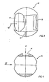
- FIG. 3 perspective side view of the ball plug according to FIGS. 1 and 2,
- FIG. 4 section through the ball plug according to line IV-IV in FIG. 5,
- FIG. 5 side view of the ball plug according to arrow V in FIG. 4,
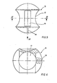
- FIG. 6 section through the ball plug in another cut,
- 7 shows a sectional view through a second exemplary embodiment of a shut-off element.
In Figur 1 ist ein zweiteiliges Gehäuse 1 gezeichnet, das aus einem Hauptteil 2 und aus einem Ergänzungsteil 3 besteht. Hauptteil 2 und Ergänzungsteil 3 sind über vier Verbindungsflansch-Schrauben 10 miteinander verbunden, wobei entsprechende Flanschdichtungen 11 zwischengeschaltet sind.In Figure 1, a two-part housing 1 is drawn, which consists of a
Das Hauptteil 2 weist oben eine zentrale Ausnehmung auf, in die der Schaft 6 eines Betätigungselementes eingreift, wobei der Schaft 6 oben drehfest mit einem Betätigurgshebel 4 über eine Befestigungsschraube 5 verbunden 1st.The
Die Dichtungswirkung zwischen dem Schaft 6, dem Hauptteil 2 und dem Medienraum des Kugelhahns erfolgt dadurch, daß in einer zentralen Ausnehmung, die von einem Deckel 30 abgeschlossen ist, eine Tellerfeder 7 angeordnet ist, die über einen Metallring 8 auf eine darunter angeordnete Dichtpackung 9 drückt.The sealing effect between the
An der Unterseite des Schaftes 6 ist eine gleichartige Dichtpackung 9 angeordnet.A similar packing 9 is arranged on the underside of the
An der Stirnseite des Schaftes 6 ist ein Zweikant 12 angefräst, der über ein axial federbelastetes Druckstück 13 in Pfeilrichtung 14 nach oben gepresst wird, wobei das Druckstück 13 in einem Schlitz 16 eines Kugelkükens 15 angeordnet ist.On the face of the
Die Abdichtung zwischen Zufluß und Abfluß übernimmt das Kugelküken 15 über die Dichtungsringe 22,23 zum Gehäuse 1.The
Gemäss den Fig. 3 bis 6 besteht das Kugelküken 15 aus einem etwa sphärischen Körper, der eine zentrale Durchgangsbohrung 17 aufweist, durch welche das Medium in Pfeilrichtung 18 hindurchströmt.3 to 6, the
Wesentliches Merkmal ist, daß im Bypass zu dem Hauptdurchgang des Kugelkükens ein Nebendurchgang geschaffen wird, in dem ein Nebenflußraum 20 vorhanden ist, der in Offenstellung des Kugelkükens von dem Mediumfluß in Pfeilrichtung 21 durchflossen ist. Dieser Nebenflußraum 20 erstreckt sich etwa ringförmig um das gesamte Kugelküken 15 herum.An essential feature is that in the bypass to the main passage of the ball plug, a secondary passage is created, in which a secondary flow space 20 is present, through which the medium flow flows in the direction of
In Offenstellung des Kugelkükens 15 gemäss Figur 1 strömt damit das Medium in Pfeilrichtung 21 durch diesen Nebenflußraum, spült diesen durch und verlässt den Nebenflußraum in Pfeilrichtung 26, wo sich dieser Durchfluß mit dem Hauptdurchfluß in Pfeilrichtung 18 vereinigt.In the open position of the
Es wird durch die Vereinigung dieser beiden Medienströme noch eine Saugwirkung auf den Nebenfluß im Nebenflußraum 20 erreicht, so daß hier hohe Durchtrittsgeschwindigkeiten erzielt werden. Der Spülungseffekt ist damit optimal.By combining these two media flows, a suction effect on the secondary flow in the secondary flow space 20 is achieved, so that high passage speeds are achieved here. The rinsing effect is optimal.
Zur Lösung der gestellten Aufgabe , daß man alle Tdräume entlasten will und von einem Medium durchspülen will, kann in einer weiteren Ausbildung der vorliegenden Erfindung noch eine Entlastungsbohrung 19 auf der Abflußseite vorgesehen sein. Hierzu wird auf Figur 2 bezug genommen. Es ist ersichtlich, daß in Schließstellung des Kugelkükens 15 die zentrale Durchgangsbohrung 17 von dem Zuflußkanal 33 abgeschlossen, wobei die Ringdichtungen 22,23 dichtend am Außenumfang des Kugelkükens 15 anliegen.To solve the problem that one wants to relieve all Tdreams and flush through a medium, a
Das im in der Durchgangsbohrung 17 befindliche Medium kann nun zur Abflußseite hin über die Entlastungsbohrung 19 abfließen, ebenso wird der untere und obere Ringraum 24 mit dem dort befindlichen Medium, welches über den Außenumfang des Kugelkükens in die Durchgangsbohrung 17 abfliesst, über die Durchgangsbohrung 19 abgeleitet.The medium located in the through-
Wesentliches Merkmal ist also, daß nach der ersten Ausführungsform in Offenstellung ein Nebenflußraum 20 geschaffen wird, der damit verhindert, daß in Offenstellung irgendwelche Toträume vorhanden sind, die nicht gespült sind.It is therefore an essential feature that, according to the first embodiment, a tributary space 20 is created in the open position, which thus prevents any dead spaces that are not flushed from being present in the open position.
In Figur 7 ist eine zweite Ausführungsform eines F igelkükens 25 gezeigt. Das dortige Kugelküken entspricht in seiner Formgebung mehr einer runden Kugel im Vergleich zu dem Ausführungsbeispiel nach den Figuren 1 - 6, wobei sowohl in Offenstellung als auch in Schließstellung stets eine dichtende Anlage der Dichtringe 22,23 am Außenumfang des Kugelkükens 25 erreicht wird.FIG. 7 shows a second embodiment of a
Der in Pfeilrichtung 18 eintretende Mediumstrom strömt wiederum durch die Durchgangsbohrung 27 hindurch und strömt zu dem Abflußkanal hinaus. In diesem Fall wird ein ansich geschlossener Ringraum 34 gebildet, der zwischen den Dichtringen 22,23 liegt. Zur Spülung dieses Ringraumes 34 in Offenstellung sind wiederum Spülkanäle 28,29 vorgesehen, die bevorzugt schräg in Richtung zur Durchströmungsrichtung vom Zuflußkanal 33 in den Ringraum 34 führen. Es erfolgt damit ein Eintritt des Mediums in Pfeilrichtung 31 in den Ringraum und dieser Ringraum wird gespült, wonach das Medium in Pfeilrichtung 32 aus dem gespülten Ringraum 34 wieder heraustritt.The medium flow entering in the direction of
Will man den Ringraum auch in Schließstellung des Kugelkükens 27 spülen, dann findet die gleiche Entlastungsbohrung 19 Anwendung, wie sie inVerbindung mit Fig. 1 und Fig. 2 dargestellt wurde.If one also wants to flush the annular space in the closed position of the
Wesentliches Merkmal ist also, daß stets bei einem Absperrorgan beliebiger Formgebung Toträume in Schließ-und Offenstellung nicht abgeschlossen werden, sondern entsprechende Kanäle zum Hauptfluß haben, so daß ein ständiger Spülfluß in diese sonst vorhandenen Toträume stattfindet.An essential feature is therefore that dead spaces in closed and open positions are not always closed in a shut-off device of any shape, but rather have corresponding channels to the main flow, so that a constant flushing flow takes place into these otherwise existing dead spaces.
Ein Spüleffekt findet selbstverständlich nur in Offenstellung dieses Kugelkükens oder dieses Kugelhahns statt, nicht aber in Schließstellung. In Schließstellung findet nur eine Entlastung des im Totraum befindlichen Mediums und ein langsamer Sickerfluß durch eine entsprechende Entlastungsbohrung statt.A flushing effect naturally only takes place in the open position of this ball plug or this ball valve, but not in the closed position. In the closed position, there is only relief of the medium in the dead space and a slow seepage flow through a corresponding relief hole.
Die Entlastungsbohrung 19 kann selbstverständlich auch an anderer Stelle und in anderer Richtung vorgesehen sein.The relief bore 19 can of course also be provided elsewhere and in a different direction.
Beispielsweise kann sie so angeordnet sein, daß ein vollständiges Absickern des in der Durchgangsbohrung 17 vorhandenen Mediums in Richtung zum Abflußkanal möglich ist.For example, it can be arranged in such a way that a complete seepage of the medium present in the through
Der Werkstoff des Kugelkükens 15,25 ist beliebig. Er kann aus Kunststoff oder Metall bestehen.The material of the ball plug 15.25 is arbitrary. It can be made of plastic or metal.
Statt der Verwendung von zwei Spülkanälen 28,29 kann auch nur ein einziger Spülkanal vorgesehen sein.Instead of using two rinsing
Ebenso können gleichartige Spülkanäle auch nach oben hin in den oberen Ringraum 34 vorgesehen werden, wodurch sich noch ein verbesserter Spüleffekt ergibt, obwohl dies nicht notwendig ist, weil der Ringraum 34 oben und unten in Fließverbindung steht.Likewise, flushing channels of the same type can also be provided upwards into the upper
- 1 Gehäuse1 housing
- 2 Hauptteil2 main part
- 3 Ergänzungsteil3 supplementary part
- 4 Betätigungshebel4 operating levers
- 5 Befestigungsschraube5 fastening screw
- 6 Schaft6 shaft
- 7 Tellerfeder7 disc spring
- 8 Metallring8 metal ring
- 9 Dichtpackung9 sealing packing
- 10 Verbindungsflanschschraube10 connecting flange screw
- 11 Flanschdichtung11 flange seal
- 12 Zweikant12 square
- 13 Druckstück13 pressure piece
- 14 Pfeilrichtung14 arrow direction
- 15 Kugelküken15 ball chicks
- 16 Schlitz16 slot
- 17 Durchgangsbohrung17 through hole
- 18 Pfeilrichtung18 arrow direction
- 19 Entlastungsbohrung19 relief bore
- 20 Nebenflußraum20 creek room
- 21 Pfeilrichtung21 arrow direction
- 22 Dichtungsring22 sealing ring
- 23 Dichtungsring23 sealing ring
- 24 Ringraum24 annulus
- 25 Kugelküken25 ball chicks
- 26 Pfeilrichtung26 direction of arrow
- 27 Durchgangsbohrung27 through hole
- 28 Spülkanal28 rinsing channel
- 29 Spülkanal29 rinsing channel
- 30 Deckel30 lids
- 31 Pfeilrichtung31 arrow direction
- 32 Pfeilrichtung32 arrow direction
- 33 Zuflußkanal33 inflow channel
- 34 Ringraum34 annulus
Claims (6)
Applications Claiming Priority (2)
| Application Number | Priority Date | Filing Date | Title |
|---|---|---|---|
| DE3248704 | 1982-12-30 | ||
| DE19823248704 DE3248704A1 (en) | 1982-12-30 | 1982-12-30 | SHUT-OFF ARMATURE FOR AGGRESSIVE MEDIA |
Publications (1)
| Publication Number | Publication Date |
|---|---|
| EP0112977A1 true EP0112977A1 (en) | 1984-07-11 |
Family
ID=6182205
Family Applications (1)
| Application Number | Title | Priority Date | Filing Date |
|---|---|---|---|
| EP83109799A Withdrawn EP0112977A1 (en) | 1982-12-30 | 1983-09-30 | Shut-off device for aggressive fluids |
Country Status (2)
| Country | Link |
|---|---|
| EP (1) | EP0112977A1 (en) |
| DE (1) | DE3248704A1 (en) |
Cited By (9)
| Publication number | Priority date | Publication date | Assignee | Title |
|---|---|---|---|---|
| EP0458980A1 (en) * | 1989-12-19 | 1991-12-04 | Asahi Yukizai Kogyo Co., Ltd | Ball valve |
| EP1130296A1 (en) * | 2000-03-04 | 2001-09-05 | Honeywell Ag | Closing valve |
| EP1039188A3 (en) * | 1999-03-24 | 2002-04-17 | ASV Stübbe GmbH & Co. KG | Ball valve |
| DE19722509C2 (en) * | 1997-05-30 | 2002-08-01 | Ewe Wilhelm Gmbh & Co Kg | Two-way ball valve |
| WO2003095876A1 (en) * | 2002-05-08 | 2003-11-20 | Imt Armaturen Ag | Shut-off cock |
| EP1522776A1 (en) * | 2003-10-09 | 2005-04-13 | Valvosanitaria Bugatti S.p.A. | Ball plug for valves or taps with the function of washing the seat wherein it is housed |
| EP1614943A1 (en) * | 2004-07-09 | 2006-01-11 | Geberit Technik Ag | Ball valve |
| US20150129788A1 (en) * | 2013-11-14 | 2015-05-14 | Charles C. Hansen, III | Ball valve for cold fluids |
| IT201800007982A1 (en) * | 2018-08-08 | 2020-02-08 | Greiner Spa | Fluid tap |
Families Citing this family (2)
| Publication number | Priority date | Publication date | Assignee | Title |
|---|---|---|---|---|
| IT210002Z2 (en) * | 1987-02-25 | 1988-11-14 | Mec Pagani Aldo Off | BALL VALVES WITH RELEASE FOR THE ELIMINATION OF THE RESIDUES. |
| DE202015006226U1 (en) * | 2015-09-04 | 2016-12-08 | Gebrüder Kemper Gmbh + Co. Kg Metallwerke | ball valve |
Citations (5)
| Publication number | Priority date | Publication date | Assignee | Title |
|---|---|---|---|---|
| DE719919C (en) * | 1937-07-22 | 1942-04-20 | Pleiger Paul | stopcock |
| US3067978A (en) * | 1960-10-31 | 1962-12-11 | Acf Ind Inc | Top entry ball valve |
| DE2321072B1 (en) * | 1973-04-26 | 1974-10-17 | Johannes Erhard, H. Waldenmaier Erben Sueddeutsche Armaturenfabrik, 7920 Heidenheim | Cock with plug eccentrically mounted in the housing |
| US4117694A (en) * | 1977-02-09 | 1978-10-03 | Belmore Richard J | Rotatable refrigerated valve |
| GB2087517A (en) * | 1980-10-14 | 1982-05-26 | Xomox Corp | Ball valve assembly |
Family Cites Families (4)
| Publication number | Priority date | Publication date | Assignee | Title |
|---|---|---|---|---|
| DE858178C (en) * | 1943-07-15 | 1952-12-04 | Escher Wyss Maschinenfabrik Ag | Tap or rotary valve, in particular with a spherical closure piece |
| DK113545B (en) * | 1966-11-01 | 1969-03-31 | W Jensen | Ball valve. |
| FR1556590A (en) * | 1968-02-22 | 1969-02-07 | ||
| US3943959A (en) * | 1974-09-04 | 1976-03-16 | Cutter Laboratories, Inc. | Two-way ball valve |
-
1982
- 1982-12-30 DE DE19823248704 patent/DE3248704A1/en not_active Ceased
-
1983
- 1983-09-30 EP EP83109799A patent/EP0112977A1/en not_active Withdrawn
Patent Citations (5)
| Publication number | Priority date | Publication date | Assignee | Title |
|---|---|---|---|---|
| DE719919C (en) * | 1937-07-22 | 1942-04-20 | Pleiger Paul | stopcock |
| US3067978A (en) * | 1960-10-31 | 1962-12-11 | Acf Ind Inc | Top entry ball valve |
| DE2321072B1 (en) * | 1973-04-26 | 1974-10-17 | Johannes Erhard, H. Waldenmaier Erben Sueddeutsche Armaturenfabrik, 7920 Heidenheim | Cock with plug eccentrically mounted in the housing |
| US4117694A (en) * | 1977-02-09 | 1978-10-03 | Belmore Richard J | Rotatable refrigerated valve |
| GB2087517A (en) * | 1980-10-14 | 1982-05-26 | Xomox Corp | Ball valve assembly |
Non-Patent Citations (1)
| Title |
|---|
| Patent Abstracts of Japan Band 5, Nr. 119, 31. Juli 1981 & JP-A-56-59067 * |
Cited By (12)
| Publication number | Priority date | Publication date | Assignee | Title |
|---|---|---|---|---|
| EP0458980A1 (en) * | 1989-12-19 | 1991-12-04 | Asahi Yukizai Kogyo Co., Ltd | Ball valve |
| EP0458980A4 (en) * | 1989-12-19 | 1992-06-03 | Asahi Yukizai Kogyo Co., Ltd | Ball valve |
| US5181539A (en) * | 1989-12-19 | 1993-01-26 | Asahi Yukizai Kogyo Co., Ltd. | Ball valve |
| DE19722509C2 (en) * | 1997-05-30 | 2002-08-01 | Ewe Wilhelm Gmbh & Co Kg | Two-way ball valve |
| EP1039188A3 (en) * | 1999-03-24 | 2002-04-17 | ASV Stübbe GmbH & Co. KG | Ball valve |
| EP1130296A1 (en) * | 2000-03-04 | 2001-09-05 | Honeywell Ag | Closing valve |
| WO2003095876A1 (en) * | 2002-05-08 | 2003-11-20 | Imt Armaturen Ag | Shut-off cock |
| EP1522776A1 (en) * | 2003-10-09 | 2005-04-13 | Valvosanitaria Bugatti S.p.A. | Ball plug for valves or taps with the function of washing the seat wherein it is housed |
| EP1614943A1 (en) * | 2004-07-09 | 2006-01-11 | Geberit Technik Ag | Ball valve |
| US20150129788A1 (en) * | 2013-11-14 | 2015-05-14 | Charles C. Hansen, III | Ball valve for cold fluids |
| US9518665B2 (en) * | 2013-11-14 | 2016-12-13 | Hantemp Corporation | Ball valve for cold fluids |
| IT201800007982A1 (en) * | 2018-08-08 | 2020-02-08 | Greiner Spa | Fluid tap |
Also Published As
| Publication number | Publication date |
|---|---|
| DE3248704A1 (en) | 1984-07-12 |
Similar Documents
| Publication | Publication Date | Title |
|---|---|---|
| DE19849742B4 (en) | Valve of the diaphragm type | |
| EP0271765B1 (en) | Self fluid controlled valve releasable by an especially solenoid controlled pilot valve | |
| DE3112037C2 (en) | ||
| EP0241880A1 (en) | Pilot valve with pressure relieving pin and main valve controlling the connection between inlet and outlet | |
| DE2450094A1 (en) | SLIDER | |
| EP0122323B1 (en) | Double-seat valve with two valve heads | |
| DE2709386A1 (en) | ONE-DIRECTIONAL FLOW LIMITER | |
| DE2645948A1 (en) | RETURNABLE FILTER DEVICE | |
| DE10203886B4 (en) | pilot valve | |
| DE3226696C2 (en) | ||
| DE2748079A1 (en) | WATER PRESSURE GAIN SYSTEM AND CONTROL VALVE AND CONTROL METHOD | |
| EP0112977A1 (en) | Shut-off device for aggressive fluids | |
| CH639181A5 (en) | LIFT VALVE. | |
| EP0401633A2 (en) | Backwashable filter mounting | |
| CH643042A5 (en) | Solenoid valve arrangement | |
| DE3420400C2 (en) | ||
| DE4012900C2 (en) | ||
| EP0278333B1 (en) | Control device for a pipe separator | |
| EP0621066B1 (en) | Back washing filter assembly | |
| AT395259B (en) | TUBE DISCONNECTOR | |
| EP1217270B1 (en) | Poppet valve | |
| DE102015223894A1 (en) | Pressure relieved valve | |
| EP0195389B1 (en) | Tube disconnector | |
| EP0139839A1 (en) | Solenoid-operated valve | |
| EP0485688B1 (en) | Aerating and venting valve |
Legal Events
| Date | Code | Title | Description |
|---|---|---|---|
| PUAI | Public reference made under article 153(3) epc to a published international application that has entered the european phase |
Free format text: ORIGINAL CODE: 0009012 |
|
| AK | Designated contracting states |
Designated state(s): AT BE CH DE FR GB IT LI LU NL SE |
|
| 17P | Request for examination filed |
Effective date: 19841220 |
|
| STAA | Information on the status of an ep patent application or granted ep patent |
Free format text: STATUS: THE APPLICATION IS DEEMED TO BE WITHDRAWN |
|
| 18D | Application deemed to be withdrawn |
Effective date: 19860402 |
|
| RIN1 | Information on inventor provided before grant (corrected) |
Inventor name: GONSIOR, WOLFGANG |