EP0112909B1 - Magnetische, kraftbeschränkte vorrichtung zum weichmachen von fleisch - Google Patents
Magnetische, kraftbeschränkte vorrichtung zum weichmachen von fleisch Download PDFInfo
- Publication number
- EP0112909B1 EP0112909B1 EP83902477A EP83902477A EP0112909B1 EP 0112909 B1 EP0112909 B1 EP 0112909B1 EP 83902477 A EP83902477 A EP 83902477A EP 83902477 A EP83902477 A EP 83902477A EP 0112909 B1 EP0112909 B1 EP 0112909B1
- Authority
- EP
- European Patent Office
- Prior art keywords
- cutting elements
- meat
- head member
- movable head
- combination according
- Prior art date
- Legal status (The legal status is an assumption and is not a legal conclusion. Google has not performed a legal analysis and makes no representation as to the accuracy of the status listed.)
- Expired
Links
- 235000013372 meat Nutrition 0.000 title claims abstract description 24
- KPLQYGBQNPPQGA-UHFFFAOYSA-N cobalt samarium Chemical compound [Co].[Sm] KPLQYGBQNPPQGA-UHFFFAOYSA-N 0.000 claims description 4
- 238000003780 insertion Methods 0.000 claims description 4
- 230000037431 insertion Effects 0.000 claims description 4
- 229910052761 rare earth metal Inorganic materials 0.000 claims description 3
- 150000002910 rare earth metals Chemical class 0.000 claims description 3
- 239000000835 fiber Substances 0.000 abstract 1
- 239000012530 fluid Substances 0.000 description 3
- 230000004907 flux Effects 0.000 description 3
- 239000000463 material Substances 0.000 description 3
- XWHPIFXRKKHEKR-UHFFFAOYSA-N iron silicon Chemical compound [Si].[Fe] XWHPIFXRKKHEKR-UHFFFAOYSA-N 0.000 description 2
- 229910000976 Electrical steel Inorganic materials 0.000 description 1
- 229910000612 Sm alloy Inorganic materials 0.000 description 1
- 230000009471 action Effects 0.000 description 1
- 238000005452 bending Methods 0.000 description 1
- 210000000988 bone and bone Anatomy 0.000 description 1
- 239000012141 concentrate Substances 0.000 description 1
- 238000010276 construction Methods 0.000 description 1
- 230000006872 improvement Effects 0.000 description 1
- 239000000696 magnetic material Substances 0.000 description 1
- 238000004519 manufacturing process Methods 0.000 description 1
- 108010091431 meat tenderizer Proteins 0.000 description 1
- 230000007246 mechanism Effects 0.000 description 1
- 230000004048 modification Effects 0.000 description 1
- 238000012986 modification Methods 0.000 description 1
- 230000008439 repair process Effects 0.000 description 1
- 210000001519 tissue Anatomy 0.000 description 1
Images

Classifications
-
- A—HUMAN NECESSITIES
- A22—BUTCHERING; MEAT TREATMENT; PROCESSING POULTRY OR FISH
- A22C—PROCESSING MEAT, POULTRY, OR FISH
- A22C9/00—Apparatus for tenderising meat, e.g. ham
- A22C9/008—Apparatus for tenderising meat, e.g. ham by piercing
-
- Y—GENERAL TAGGING OF NEW TECHNOLOGICAL DEVELOPMENTS; GENERAL TAGGING OF CROSS-SECTIONAL TECHNOLOGIES SPANNING OVER SEVERAL SECTIONS OF THE IPC; TECHNICAL SUBJECTS COVERED BY FORMER USPC CROSS-REFERENCE ART COLLECTIONS [XRACs] AND DIGESTS
- Y10—TECHNICAL SUBJECTS COVERED BY FORMER USPC
- Y10T—TECHNICAL SUBJECTS COVERED BY FORMER US CLASSIFICATION
- Y10T83/00—Cutting
- Y10T83/869—Means to drive or to guide tool
- Y10T83/8719—With transmission yieldable on overload
Definitions
- This invention relates to a mechanical apparatus for tenderizing meat.
- the apparatus employs a multiplicity of slender cutting elements to sever the tough, fibrous meat tissues.
- the cutting elements penetrate the meat to be tenderized with a true force-limiting action, thereby allowing bone-in tenderizing treatment of large intermediate cuts of meat prior to the final butchering cuts without damaging the cutting elements on the bone.
- the present invention has for its principal object the provision of a magnetic force-limited apparatus to replace the fluid-operated, force-limited apparatus presently utilized in the apparatus disclosed in United States Patent No. 3,535,734.
- the features of the invention may be realized by the use of rare earth magnets of the cobalt-samarium variety. These magnets are characterized by high field strength and retentivity.
- the magnets may be incorporated in a movable head member which has a vertically-reciprocable set of closely-spaced, independently-movable, cutting elements disposed over a conveyor belt which is programmed for longitudinal and lateral movements as the cutting elements reciprocate vertically.
- the cutting elements may have special pole pieces of electrical steel with a high magnetic saturation level attached to the ends opposite the cutting edges.
- the magnets in the movable head member attract the pole pieces thereby holding the cutting elements in a fully extended downward position until a force is encountered which exceeds the holding power of the magnet, at which time the cutting element retracts before it is damaged by excessive force.
- the magnet size and pole piece design are. selected to provide the desired holding power to be used with a given size of cutting element to prevent damage.
- FIG. 1 is a perspective view in simplified form of an apparatus embodying the features of the present invention
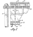
- Fig. 2 is a partial cross-sectional view of a first embodiment of the invention showing the movable head member at the top of its stroke
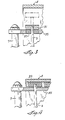
- Fig. 3 is a partial cross-sectional view of the mechanism of Fig. 2 in which the movable head member is on its downward stroke, and in which the cutting element is shown in dotted lines as having met the predetermined resistance required to cause the cutting element to retract
- Fig. 4 is a partial cross-sectional view of a second embodiment of the invention showing the movable head member at the stop of its stroke.
- FIG. 1 shows an apparatus which is generally similar in appearance and function to the meat tenderizer apparatus disclosed in United States Patent No. 3,535,734.
- the principal difference between the two is the absence of the fluid pressure system in the present apparatus.
- the fluid pressure, force-limiting system of the prior art has been replaced with a magnetic force-limiting system in which the cutting elements are held in position by magnetic attraction until a predetermined resistance is encountered by the cutting elements in piercing the meat to be tenderized. When the predetermined resistance exceeds the force of the magnetic attraction, the cutting elements retract and are not damaged by being subjected to excessive force.
- the cabinet 1 has mounted thereon a movable head member 3 which is supported over conveyor belt 2 by a pair of head rod supports 5 and 7.
- a plurality of cutting elements shown generally at 9 depend from the lower surface of movable head member 3, and project through upper guide 13.
- the cutting elements 9 are arranged in two groups, designated generally as 8 and 10.
- the cutting elements within each group have their cutting edges in parallel relationship.
- the cutting edges of the elements in group 8 are disposed orthogonally with respect to the cutting edges of the elements of group 10.
- the groups 8 and 10 are separated by a divider plate 12.
- a lower guide and hold-down member 23 Beneath the cutting elements 9 and depending from movable head member 3 is a lower guide and hold-down member 23 which is mounted on and held in position by hold-down rod supports 15,17,19 and 21. Both upper guide 13 and lower guide and hold-down member 23 are provided with spaced apertures which coincide with the positioning of cutting elements 9 to provide free passage therethrough.
- a partial detail showing of the movable head member 3 can be seen from Fig. 2.
- a cutting element 9 has a pole piece 31 attached to the end opposite the cutting edge 33.
- the cutting element 9 is positioned for vertically reciprocating movement through upper guide member 13.
- Guide member 13 is made up of comb members 14 and 16 having transverse and longitudinal tines, respectively, which form a supporting guide structure for the cutting element 9.
- a supporting plate member 35 is attached to head rod supports 5 and 7 for movement therewith.
- a magnet, such as magnet 37, is inset in supporting plate member 35 to attract the pole piece 31 of the associated cutting element 9, thereby holding it in a rigid downwardly depending position.
- a magnetic flux density which exceeds the flux density obtainable in the material of the magnet being employed.
- the structure shown in Fig. 2 would be slightly modified to insert additional pole piece material between the magnet 37 and the pole piece 31 to concentrate the flux density adjacent the magnet 37 and to increase the magnetic attraction exerted on pole piece 31.
- Such modified structure could be effected in several different variations in accordance with principles which are well known in the art. No specific modification is shown since the elementary use of the magnet 37 and attracted pole piece 31 clearly illustrates the invention.
- Fig. 3 is a partial detail similar to Fig. 2, but in which the supporting plate member 35 has moved downwardly to a point where the cutting element 9 has encountered resistance in excess of the predetermined force required to overcome the magnetic attraction.
- Cutting element 9 with pole piece 31 is shown in phantom view as having been pushed back into movable head member 3, thereby protecting cutting element 9 from bending or breaking.
- the magnetic materials utilized in accordance with the present invention are selected from the rare earth varieties.
- a cobalt-samarium alloy has been found to possess the required high field strength and retentivity necessary to attain the attractive forces consonant with the size limitations in the structure shown.
- Special pole piece material of silicon iron is used in conjunction with the cobalt-samarium magnets.
- the cutting elements 9 are expandable parts and must be replaced from time to time. For this reason it has been more economical to manufacture the cutting elements with pole pieces attached rather than with magnets attached, because the magnets are more expensive than the pole pieces. It will be appreciated, however, that from the standpoint of the invention, it would be just as feasible to place the magnet on the cutting element, and to incorporate the pole piece into the supporting plate member.
- Fig. 4 is a partial detail in which is shown a magnet 39 attached to cutting element 9.
- the supporting plate member 35 is constructed of silicon iron and functions as a pole piece for the magnets associated with the individual cutting elements.
- the operation of this embodiment of the invention is exactly the same as that shown in Figs. 2 and 3.
Landscapes
- Life Sciences & Earth Sciences (AREA)
- Engineering & Computer Science (AREA)
- Wood Science & Technology (AREA)
- Zoology (AREA)
- Food Science & Technology (AREA)
- Processing Of Stones Or Stones Resemblance Materials (AREA)
- Perforating, Stamping-Out Or Severing By Means Other Than Cutting (AREA)
Claims (11)
Applications Claiming Priority (2)
| Application Number | Priority Date | Filing Date | Title |
|---|---|---|---|
| US391835 | 1982-06-24 | ||
| US06/391,835 US4437207A (en) | 1982-06-24 | 1982-06-24 | Magnetic, force-limited apparatus for tenderizing meat |
Publications (3)
| Publication Number | Publication Date |
|---|---|
| EP0112909A1 EP0112909A1 (de) | 1984-07-11 |
| EP0112909A4 EP0112909A4 (de) | 1984-10-31 |
| EP0112909B1 true EP0112909B1 (de) | 1988-11-02 |
Family
ID=23548129
Family Applications (1)
| Application Number | Title | Priority Date | Filing Date |
|---|---|---|---|
| EP83902477A Expired EP0112909B1 (de) | 1982-06-24 | 1983-06-24 | Magnetische, kraftbeschränkte vorrichtung zum weichmachen von fleisch |
Country Status (5)
| Country | Link |
|---|---|
| US (1) | US4437207A (de) |
| EP (1) | EP0112909B1 (de) |
| AU (1) | AU1821483A (de) |
| DE (1) | DE3378350D1 (de) |
| WO (1) | WO1984000096A1 (de) |
Families Citing this family (8)
| Publication number | Priority date | Publication date | Assignee | Title |
|---|---|---|---|---|
| DK166763C (da) * | 1983-03-16 | 1993-07-12 | Immuno Ag | Immunoglobulin-g-holdig fraktion |
| US5525102A (en) * | 1995-09-12 | 1996-06-11 | Jaccard Corporation | Meat-tenderizing machine |
| US6648745B2 (en) | 2001-09-19 | 2003-11-18 | Bobrowski Clamounte R. | Meat tenderizer with force limiting apparatus and orthogonal blade set |
| US6533653B1 (en) | 2001-09-19 | 2003-03-18 | Bobrowski Clamounte R. | Meat tenderizer with force limiting apparatus and orthogonal blade set |
| SI2440558T1 (sl) | 2009-06-08 | 2015-10-30 | Takeda Pharmaceutical Company Limited | Spojine dihidropirolonaftiridinona kot inhibitorji JAK |
| NL2006075C2 (en) | 2011-01-26 | 2012-07-30 | Foodmate B V | Rotationally indexed article support for a conveyor system having an alignment station. |
| US9210946B2 (en) * | 2012-10-15 | 2015-12-15 | Steven P. Hoffman | Potato piercing apparatus |
| ITUA20163218A1 (it) * | 2016-05-06 | 2017-11-06 | Vepa Srl | Macchina inteneritrice per carni a trattenta magnetica |
Family Cites Families (6)
| Publication number | Priority date | Publication date | Assignee | Title |
|---|---|---|---|---|
| US3535734A (en) | 1969-03-04 | 1970-10-27 | Henry M Ross | Fluid-operated,force-limited apparatus for tenderizing meat |
| US3736583A (en) | 1971-01-13 | 1973-05-29 | Heinz Co H J | Apparatus for detecting the presence of hard solid particles in a body of softer solid substance |
| US4055872A (en) | 1976-07-06 | 1977-11-01 | Hollymatic Corporation | Apparatus for tenderizing meat |
| US4086683A (en) | 1976-09-30 | 1978-05-02 | Hollymatic Corporation | Meat tenderizing apparatus |
| US4216566A (en) | 1978-06-19 | 1980-08-12 | Bettcher Industries, Inc. | Tenderizer |
| FR2464029A1 (fr) | 1979-09-04 | 1981-03-06 | Coupax Sa | Dispositif attendrisseur pour viande de boucherie |
-
1982
- 1982-06-24 US US06/391,835 patent/US4437207A/en not_active Expired - Lifetime
-
1983
- 1983-06-24 AU AU18214/83A patent/AU1821483A/en not_active Abandoned
- 1983-06-24 DE DE8383902477T patent/DE3378350D1/de not_active Expired
- 1983-06-24 EP EP83902477A patent/EP0112909B1/de not_active Expired
- 1983-06-24 WO PCT/US1983/000967 patent/WO1984000096A1/en not_active Ceased
Also Published As
| Publication number | Publication date |
|---|---|
| US4437207A (en) | 1984-03-20 |
| EP0112909A1 (de) | 1984-07-11 |
| EP0112909A4 (de) | 1984-10-31 |
| AU1821483A (en) | 1984-01-26 |
| WO1984000096A1 (en) | 1984-01-19 |
| DE3378350D1 (en) | 1988-12-08 |
Similar Documents
| Publication | Publication Date | Title |
|---|---|---|
| EP0112909B1 (de) | Magnetische, kraftbeschränkte vorrichtung zum weichmachen von fleisch | |
| EP0119787B1 (de) | Litzensteuervorrichtung | |
| EP0278122A1 (de) | Vorrichtung zum Trennen von Fleisch und Knochen von Geflügelschenkeln oder Teilen davon | |
| JP2912015B2 (ja) | 細長の人工的な草繊維を地中に挿入するための装置 | |
| EP2656736A1 (de) | Verfahren und Vorrichtung zur Verarbeitung eines Geflügelschlachtkörperteils | |
| US20150313407A1 (en) | Device and method for composing satays | |
| US4575939A (en) | Cutlery storage apparatus | |
| US3535734A (en) | Fluid-operated,force-limited apparatus for tenderizing meat | |
| US4242774A (en) | Meat tenderer | |
| US4055872A (en) | Apparatus for tenderizing meat | |
| ES2246190T1 (es) | Procedimiento para extraer y aislar alambres de acero magnetizables y cortados a medida de un almacenamiento de alambres sueltos. | |
| DE2640727C2 (de) | Selektionseinrichtung einer Jacquardmaschine | |
| US3651541A (en) | Method of guiding piercing instruments | |
| FR2326867A1 (fr) | Attendrisseur de viande | |
| CN210361658U (zh) | 自动裁书模切机 | |
| WO2000010399A1 (en) | Method for filleting of fish and filleting machine for use in the method | |
| SU1501994A1 (ru) | Прив зь дл животных | |
| KR102701989B1 (ko) | 육류발골장치 | |
| US6648745B2 (en) | Meat tenderizer with force limiting apparatus and orthogonal blade set | |
| US6533653B1 (en) | Meat tenderizer with force limiting apparatus and orthogonal blade set | |
| DE1811901U (de) | Querdraht-zufuehrungsvorrichtung fuer gitterschweissmaschinen. | |
| SE406257B (sv) | Anordning for fasthallning av ett eller flera kretskort i en telefonapparat | |
| US3445987A (en) | Device for packing ferromagnetic pieces | |
| SU1727656A1 (ru) | Молотильное устройство | |
| SE9300368D0 (sv) | Fiskfilemaskin |
Legal Events
| Date | Code | Title | Description |
|---|---|---|---|
| PUAI | Public reference made under article 153(3) epc to a published international application that has entered the european phase |
Free format text: ORIGINAL CODE: 0009012 |
|
| AK | Designated contracting states |
Designated state(s): AT BE CH DE FR GB LI LU NL SE |
|
| 17P | Request for examination filed |
Effective date: 19840830 |
|
| RBV | Designated contracting states (corrected) |
Designated state(s): BE DE FR GB NL |
|
| R17P | Request for examination filed (corrected) |
Effective date: 19840523 |
|
| 17Q | First examination report despatched |
Effective date: 19880108 |
|
| GRAA | (expected) grant |
Free format text: ORIGINAL CODE: 0009210 |
|
| AK | Designated contracting states |
Kind code of ref document: B1 Designated state(s): BE DE FR GB NL |
|
| REF | Corresponds to: |
Ref document number: 3378350 Country of ref document: DE Date of ref document: 19881208 |
|
| ET | Fr: translation filed | ||
| PLBE | No opposition filed within time limit |
Free format text: ORIGINAL CODE: 0009261 |
|
| STAA | Information on the status of an ep patent application or granted ep patent |
Free format text: STATUS: NO OPPOSITION FILED WITHIN TIME LIMIT |
|
| 26N | No opposition filed | ||
| PGFP | Annual fee paid to national office [announced via postgrant information from national office to epo] |
Ref country code: GB Payment date: 19900614 Year of fee payment: 8 |
|
| PGFP | Annual fee paid to national office [announced via postgrant information from national office to epo] |
Ref country code: FR Payment date: 19900619 Year of fee payment: 8 |
|
| PGFP | Annual fee paid to national office [announced via postgrant information from national office to epo] |
Ref country code: DE Payment date: 19900622 Year of fee payment: 8 |
|
| PGFP | Annual fee paid to national office [announced via postgrant information from national office to epo] |
Ref country code: BE Payment date: 19900627 Year of fee payment: 8 |
|
| PGFP | Annual fee paid to national office [announced via postgrant information from national office to epo] |
Ref country code: NL Payment date: 19900630 Year of fee payment: 8 |
|
| PG25 | Lapsed in a contracting state [announced via postgrant information from national office to epo] |
Ref country code: GB Effective date: 19910624 |
|
| PG25 | Lapsed in a contracting state [announced via postgrant information from national office to epo] |
Ref country code: BE Effective date: 19910630 |
|
| BERE | Be: lapsed |
Owner name: HENRY M. Effective date: 19910630 |
|
| PG25 | Lapsed in a contracting state [announced via postgrant information from national office to epo] |
Ref country code: NL Effective date: 19920101 |
|
| NLV4 | Nl: lapsed or anulled due to non-payment of the annual fee | ||
| GBPC | Gb: european patent ceased through non-payment of renewal fee | ||
| PG25 | Lapsed in a contracting state [announced via postgrant information from national office to epo] |
Ref country code: FR Effective date: 19920228 |
|
| PG25 | Lapsed in a contracting state [announced via postgrant information from national office to epo] |
Ref country code: DE Effective date: 19920401 |
|
| REG | Reference to a national code |
Ref country code: FR Ref legal event code: ST |