EP0112792A1 - Regelvorrichtung für die Verstellung der Flügel einer grossen Windkraftmaschine - Google Patents
Regelvorrichtung für die Verstellung der Flügel einer grossen Windkraftmaschine Download PDFInfo
- Publication number
- EP0112792A1 EP0112792A1 EP83630180A EP83630180A EP0112792A1 EP 0112792 A1 EP0112792 A1 EP 0112792A1 EP 83630180 A EP83630180 A EP 83630180A EP 83630180 A EP83630180 A EP 83630180A EP 0112792 A1 EP0112792 A1 EP 0112792A1
- Authority
- EP
- European Patent Office
- Prior art keywords
- pitch angle
- blade pitch
- wind turbine
- wind
- output
- Prior art date
- Legal status (The legal status is an assumption and is not a legal conclusion. Google has not performed a legal analysis and makes no representation as to the accuracy of the status listed.)
- Granted
Links
- 230000004044 response Effects 0.000 abstract description 2
- 230000006870 function Effects 0.000 description 13
- 230000001360 synchronised effect Effects 0.000 description 3
- 238000010586 diagram Methods 0.000 description 2
- 230000002708 enhancing effect Effects 0.000 description 2
- 238000005259 measurement Methods 0.000 description 2
- 230000001133 acceleration Effects 0.000 description 1
- 238000004458 analytical method Methods 0.000 description 1
- 238000010276 construction Methods 0.000 description 1
- 230000000694 effects Effects 0.000 description 1
- 239000012530 fluid Substances 0.000 description 1
- 238000000034 method Methods 0.000 description 1
Images

Classifications
-
- F—MECHANICAL ENGINEERING; LIGHTING; HEATING; WEAPONS; BLASTING
- F03—MACHINES OR ENGINES FOR LIQUIDS; WIND, SPRING, OR WEIGHT MOTORS; PRODUCING MECHANICAL POWER OR A REACTIVE PROPULSIVE THRUST, NOT OTHERWISE PROVIDED FOR
- F03D—WIND MOTORS
- F03D7/00—Controlling wind motors
-
- F—MECHANICAL ENGINEERING; LIGHTING; HEATING; WEAPONS; BLASTING
- F03—MACHINES OR ENGINES FOR LIQUIDS; WIND, SPRING, OR WEIGHT MOTORS; PRODUCING MECHANICAL POWER OR A REACTIVE PROPULSIVE THRUST, NOT OTHERWISE PROVIDED FOR
- F03D—WIND MOTORS
- F03D7/00—Controlling wind motors
- F03D7/02—Controlling wind motors the wind motors having rotation axis substantially parallel to the air flow entering the rotor
- F03D7/022—Adjusting aerodynamic properties of the blades
- F03D7/0224—Adjusting blade pitch
-
- F—MECHANICAL ENGINEERING; LIGHTING; HEATING; WEAPONS; BLASTING
- F05—INDEXING SCHEMES RELATING TO ENGINES OR PUMPS IN VARIOUS SUBCLASSES OF CLASSES F01-F04
- F05B—INDEXING SCHEME RELATING TO WIND, SPRING, WEIGHT, INERTIA OR LIKE MOTORS, TO MACHINES OR ENGINES FOR LIQUIDS COVERED BY SUBCLASSES F03B, F03D AND F03G
- F05B2220/00—Application
- F05B2220/70—Application in combination with
- F05B2220/706—Application in combination with an electrical generator
-
- F—MECHANICAL ENGINEERING; LIGHTING; HEATING; WEAPONS; BLASTING
- F05—INDEXING SCHEMES RELATING TO ENGINES OR PUMPS IN VARIOUS SUBCLASSES OF CLASSES F01-F04
- F05B—INDEXING SCHEME RELATING TO WIND, SPRING, WEIGHT, INERTIA OR LIKE MOTORS, TO MACHINES OR ENGINES FOR LIQUIDS COVERED BY SUBCLASSES F03B, F03D AND F03G
- F05B2260/00—Function
- F05B2260/70—Adjusting of angle of incidence or attack of rotating blades
- F05B2260/74—Adjusting of angle of incidence or attack of rotating blades by turning around an axis perpendicular the rotor centre line
-
- F—MECHANICAL ENGINEERING; LIGHTING; HEATING; WEAPONS; BLASTING
- F05—INDEXING SCHEMES RELATING TO ENGINES OR PUMPS IN VARIOUS SUBCLASSES OF CLASSES F01-F04
- F05B—INDEXING SCHEME RELATING TO WIND, SPRING, WEIGHT, INERTIA OR LIKE MOTORS, TO MACHINES OR ENGINES FOR LIQUIDS COVERED BY SUBCLASSES F03B, F03D AND F03G
- F05B2270/00—Control
- F05B2270/30—Control parameters, e.g. input parameters
- F05B2270/328—Blade pitch angle
-
- Y—GENERAL TAGGING OF NEW TECHNOLOGICAL DEVELOPMENTS; GENERAL TAGGING OF CROSS-SECTIONAL TECHNOLOGIES SPANNING OVER SEVERAL SECTIONS OF THE IPC; TECHNICAL SUBJECTS COVERED BY FORMER USPC CROSS-REFERENCE ART COLLECTIONS [XRACs] AND DIGESTS
- Y02—TECHNOLOGIES OR APPLICATIONS FOR MITIGATION OR ADAPTATION AGAINST CLIMATE CHANGE
- Y02E—REDUCTION OF GREENHOUSE GAS [GHG] EMISSIONS, RELATED TO ENERGY GENERATION, TRANSMISSION OR DISTRIBUTION
- Y02E10/00—Energy generation through renewable energy sources
- Y02E10/70—Wind energy
- Y02E10/72—Wind turbines with rotation axis in wind direction
Definitions
- This invention relates to the control of blade pitch angle in horizontal axis wind turbine-generators and particularly to blade pitch angle control under conditions of low wind velocity.
- Modern, large horizontal axis wind turbine-generators generally include two or more variable pitch blades mounted on a rotor which drives a synchronous generator through a gear box, the gear box serving to step up the rotational speed of the main turbine shaft to the speed required for synchronous operation of the generator.
- a suitable blade pitch control system for large wind turbine-generators is disclosed in U.S. Patent No. 4,193,005 to Kos et al. This control system is a closed-loop system which provides a blade pitch angle reference signal to a blade pitch change actuation system based on such parameters as wind conditions, desired turbine-generator operating conditions and actual turbine-generator operating conditions.
- the system of the Kos et al patent includes four discrete controllers: a first controlling rotor acceleration during start up, a second controlling rotor deceleration during shutdown, a third controlling rotor speed when the synchronous generator is off-line and a fourth controlling power or torque when the generator is on-line.
- the controllers provide a time derivative pitch angle reference signal as an input signal to an integrator.
- the output of the integrator is the blade pitch angle reference signal noted hereinabove.
- the integrator includes maximum and minimum blade angle stops. The maximum stop corresponds to a blade pitch angle of 90° (full blade feathering) while the minimum blade angle stop is variable, being a function of rotor speed and measured wind speed.
- the blade pitch angle reference signal set by the controller is limited to a minimum value (the minimumo!ntegrator stop) under wind velocity conditions between cut-in velocity (the minimum wind velocity at which the wind turbine-generator is capable of producing useful power), and rated velocity (the minimum wind velocity at which the wind turbine-generator may produce rated power).
- the pitch angle of the blades be set to such a minimum value for capture of the greatest possible amount of energy from the wind stream. At wind velocities greater than those within this range, more than enough wind energy is available for the generation of rated power and hence, energy is "spilled" from the blades as the wind turbine operates.
- the blades must be precisely set at minimum pitch angles wherein no significant amount of energy is spilled from the blades.
- a minimum pitch angle reference signal for wind turbine blade pitch control at less than rated wind velocity conditions is determined on the basis of turbine output power or torque rather than wind velocity measured at a point location.
- the blade pitch angle reference signal is calculated on the basis of conditions integrated over the entire wind turbine rotor rather than at a single point location removed therefrom.
- torque and power are more accurately measurable than is wind velocity thereby further enhancing the accuracy of the resulting minimum blade pitch angle reference signal.
- Such enhancement of the accuracy of calculated blade pitch angle signal optimizes the wind energy capture capabilities of the turbine and, therefore, the output capabilities thereof.
- the blade pitch angle control system of the present invention is shown generally within broken line 10.
- the system is input with the time derivative (êR) of a blade pitch angle reference signal on line 15, a signal (N R ) indicative of the actual frequency of the rotation of the wind turbine rotor on line 20, and on line 25 a signal (P) indicative of actual output power of the wind turbine.
- the frequency of rotation and power signals may be readily obtained from suitable transducers 30 and 35, respectively, which are well known in the art.
- the time derivative (a R ) of the blade pitch angle signal is obtained from controller 40 which for example, may comprise the controller of the hereinabove noted U.S. Patent No. 4,193,005 less the integrator section thereof shown in Fig. 8 of that patent.
- the R signal on line 15 is provided from, for example, the mode selector 96 of the Kos et al system, further details regarding the construction and operation of the Kos et al system being readily available from the patent.
- control system 10 of the preferred embodiment corresponds generally to that portion of the system shown in Fig. 8 of the patent and referred to at 104 of the block diagram of Fig. 3 thereof.
- the derivative signal on line 15 is fed to a limiter 45 which limits the signal to values consistent with the capabilities of the blade pitch actuators in the pitch change actuation system of the turbine.
- limiter 45 limits the derivative signal to values corresponding to the capabilities of a slew pump which provides pressurized hydraulic fluid to the actuators.
- the limited derivative signal is fed to a summing junction 50 which takes the difference between the limited derivative signal and an output signal on line 60 from circuit 55 and feeds this difference to integrator 70 via line 75.
- Integrator 70 integrates the derivative signal, thereby providing a blade pitch angle reference signal a R along line 80 to a blade pitch actuation system 85 which sets the pitch of the wind turbine blades to that reference signal.
- the pitch actuation system forms no part of the present invention and is, therefore, not described herein.
- a suitable wind turbine pitch actuation system is described in U.S. Patent No. 4,348,155 to Barnes et al.
- the blade pitch angle reference signal from line 80 is fed to circuit 55 through line 90.
- Circuit 55 compares the pitch angle reference signal to maximum and minimum allowable pitch angle values therein and, if the reference signal on line 90 falls between the maximum and allowable signals, provides a zero output to summing junction 50 through line 60.
- circuit 55 provides a high gain output signal on line 60 which effectively cancels the time derivative input signal to summing junction 50 to shut integrator 70 off thereby limiting the maximum allowable pitch angle reference signal provided to actuator system 85 to 90°.
- a minimum allowable pitch angle (MIN B) circuit 55 provides a high gain output signal on line 60 which in summing junction 50, cancels the time derivative signal to prevent the integrator 70 from integrating to a value less than a minimum value corresponding to the desired blade pitch angle setting under minimum (less than rated) wind velocity conditions.
- the maximum blade pitch angle signal within circuit 55 is a constant (90°) stored therein while the minimum pitch angle signal (MIN is a variable which is input to circuit 55 from function generator 95 through line 100.
- the wind turbine's blades are set to the MIN ⁇ position corresponding to optimal capture of wind energy by the blades with no "spillage" of wind therefrom.
- the accuracy of the MIN ⁇ signal must be optimized.
- such signal accuracy is achieved by function generator 95 which provides a MIN ⁇ output signal to line 100 based upon the rotational frequency of the wind turbine rotor and the power output thereof rather than wind velocity at a point location.
- values of MIN ⁇ are stored within function generator 95 as functions of P.
- P is indicative of the actual output power of the turbine and N R the frequency of rotation of the turbine rotor.
- NO is the nominal frequency of rotation of the turbine rotor or, in other words, the maximum frequency of rotation of the rotor at cut-in wind velocity.
- output power is itself a function of wind velocity.
- this signal is in effect based on wind velocity conditions across the entire diameter of the wind turbine rotor thereby enhancing the accuracy of this reference signal.
- the accuracy with which turbine output power is measured further enhances the accuracy of the pitch angle reference signal.
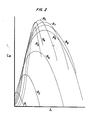
- Function generator 95 may be programmed as follows. Referring to Fig. 2, there is shown a performance map for a typical large wind turbine-generator, the map being determined by known analytical techniques on the basis of turbine geometry. It is seen that the performance map comprises a family of curves which plot power coefficient C (the ratio of the amount of power which may be captured by the turbine to the amount of available power in the wind stream intercepted by the turbine) against velocity ratio for a number of different blade pitch angle settings. It will be seen that for any one value of velocity ratio X, there exists a corresponding single maximum power coefficient at a single pitch angle. Stated conversely, for every maximum power coefficient, there is a blade angle setting by which the wind turbine may attain such a power coefficient for a given velocity ratio. For any velocity ratio X, from the data available in Fig. 2, a nominal wind velocity may be calculated from the following expression: wherein D is the diameter of the wind turbine rotor. Having calculated the nominal wind velocity, nominal power may be calculated from the expression: wherein
- Function generator 95 provides the blade pitch angle setting (MIN ⁇ ) at which such nominal output power is achieved at a given wind velocity, or, in other words, the blade pitch angle setting wherein an optimum amount of energy may be captured from the wind at such a velocity.
- the expression is a correction factor necessitated by the fact that the calculated power is a nominal power. Actual power is related to nominal power by the expression .
- the wind turbine blade pitch control system of the present invention is readily implemented by either analog or digital techniques. Accordingly, the circuit 95 described hereinabove as a function generator may comprise a digital data lookup memory. Likewise, the other components described hereinabove may comprise analog or digital apparatus. While the control system has been described with respect to providing a minimum blade angle system based on output power, it will be appreciated that the pitch angle signal may be based on turbine shaft torque with equal utility, it being recognized that actual torque, like power, provides a basis for a minimum blade angle setting which essentially integrates wind speed conditions across the entire turbine rotor.
Applications Claiming Priority (2)
| Application Number | Priority Date | Filing Date | Title |
|---|---|---|---|
| US44012282A | 1982-11-08 | 1982-11-08 | |
| US440122 | 1982-11-08 |
Publications (2)
| Publication Number | Publication Date |
|---|---|
| EP0112792A1 true EP0112792A1 (de) | 1984-07-04 |
| EP0112792B1 EP0112792B1 (de) | 1987-05-20 |
Family
ID=23747533
Family Applications (1)
| Application Number | Title | Priority Date | Filing Date |
|---|---|---|---|
| EP83630180A Expired EP0112792B1 (de) | 1982-11-08 | 1983-11-04 | Regelvorrichtung für die Verstellung der Flügel einer grossen Windkraftmaschine |
Country Status (14)
| Country | Link |
|---|---|
| EP (1) | EP0112792B1 (de) |
| JP (1) | JPS59101587A (de) |
| KR (1) | KR920001092B1 (de) |
| AU (1) | AU559325B2 (de) |
| BR (1) | BR8306078A (de) |
| CA (1) | CA1234543A (de) |
| DE (2) | DE3371673D1 (de) |
| DK (1) | DK167235B1 (de) |
| ES (1) | ES8407557A1 (de) |
| FI (1) | FI77092C (de) |
| IL (1) | IL70133A (de) |
| IN (1) | IN158707B (de) |
| NO (1) | NO161190C (de) |
| ZA (1) | ZA838157B (de) |
Cited By (5)
| Publication number | Priority date | Publication date | Assignee | Title |
|---|---|---|---|---|
| US5075564A (en) * | 1989-12-19 | 1991-12-24 | Hickey John J | Combined solar and wind powered generator with spiral surface pattern |
| EP2177754A3 (de) * | 2008-10-16 | 2013-07-10 | General Electric Company | Blattwinkelverwaltungsverfahren und Verwaltungssystem. |
| CN104074679A (zh) * | 2014-07-02 | 2014-10-01 | 国电联合动力技术有限公司 | 一种变速变桨距风电机组全风速限功率优化控制方法 |
| CN112055782A (zh) * | 2018-05-03 | 2020-12-08 | 通用电气公司 | 用于控制风力涡轮转子叶片的桨距角的系统和方法 |
| CN112796942A (zh) * | 2021-03-26 | 2021-05-14 | 中国华能集团清洁能源技术研究院有限公司 | 一种风电机组桨距角的控制方法、系统、设备及存储介质 |
Families Citing this family (2)
| Publication number | Priority date | Publication date | Assignee | Title |
|---|---|---|---|---|
| US7452185B2 (en) | 2003-09-10 | 2008-11-18 | Mitsubishi Heavy Industries, Ltd | Blade-pitch-angle control device and wind power generator |
| JP6022416B2 (ja) | 2013-06-27 | 2016-11-09 | 株式会社神戸製鋼所 | チタンまたはチタン合金からなる鋳塊の連続鋳造装置 |
Citations (6)
| Publication number | Priority date | Publication date | Assignee | Title |
|---|---|---|---|---|
| GB1050088A (de) * | ||||
| FR1314086A (fr) * | 1961-12-28 | 1963-01-04 | Brown | Installation génératrice de courant comportant une turbine et une génératrice à vitesse angulaire fortement variable |
| US3974395A (en) * | 1975-06-02 | 1976-08-10 | Clark Bright | Power generating apparatus |
| US4160170A (en) * | 1978-06-15 | 1979-07-03 | United Technologies Corporation | Wind turbine generator pitch control system |
| EP0008584A1 (de) * | 1978-08-17 | 1980-03-05 | United Technologies Corporation | Mehrfach-Kontrollsystem für eine Windkraftmaschine |
| GB2071781A (en) * | 1980-03-17 | 1981-09-23 | United Technologies Corp | Wind turbine blade pitch control system |
-
1983
- 1983-10-28 CA CA000439908A patent/CA1234543A/en not_active Expired
- 1983-11-01 ZA ZA838157A patent/ZA838157B/xx unknown
- 1983-11-02 NO NO833993A patent/NO161190C/no unknown
- 1983-11-04 AU AU20999/83A patent/AU559325B2/en not_active Ceased
- 1983-11-04 DE DE8383630180T patent/DE3371673D1/de not_active Expired
- 1983-11-04 BR BR8306078A patent/BR8306078A/pt not_active IP Right Cessation
- 1983-11-04 IL IL70133A patent/IL70133A/xx not_active IP Right Cessation
- 1983-11-04 EP EP83630180A patent/EP0112792B1/de not_active Expired
- 1983-11-04 DE DE198383630180T patent/DE112792T1/de active Pending
- 1983-11-05 IN IN1365/CAL/83A patent/IN158707B/en unknown
- 1983-11-07 DK DK508483A patent/DK167235B1/da not_active IP Right Cessation
- 1983-11-07 FI FI834074A patent/FI77092C/fi not_active IP Right Cessation
- 1983-11-07 ES ES527072A patent/ES8407557A1/es not_active Expired
- 1983-11-08 KR KR1019830005284A patent/KR920001092B1/ko not_active IP Right Cessation
- 1983-11-08 JP JP58209763A patent/JPS59101587A/ja active Granted
Patent Citations (6)
| Publication number | Priority date | Publication date | Assignee | Title |
|---|---|---|---|---|
| GB1050088A (de) * | ||||
| FR1314086A (fr) * | 1961-12-28 | 1963-01-04 | Brown | Installation génératrice de courant comportant une turbine et une génératrice à vitesse angulaire fortement variable |
| US3974395A (en) * | 1975-06-02 | 1976-08-10 | Clark Bright | Power generating apparatus |
| US4160170A (en) * | 1978-06-15 | 1979-07-03 | United Technologies Corporation | Wind turbine generator pitch control system |
| EP0008584A1 (de) * | 1978-08-17 | 1980-03-05 | United Technologies Corporation | Mehrfach-Kontrollsystem für eine Windkraftmaschine |
| GB2071781A (en) * | 1980-03-17 | 1981-09-23 | United Technologies Corp | Wind turbine blade pitch control system |
Non-Patent Citations (1)
| Title |
|---|
| BROWN BOVERI REVIEW, vol. 69, no. 3, March 1982, pages 57-64, Baden, CH. * |
Cited By (8)
| Publication number | Priority date | Publication date | Assignee | Title |
|---|---|---|---|---|
| US5075564A (en) * | 1989-12-19 | 1991-12-24 | Hickey John J | Combined solar and wind powered generator with spiral surface pattern |
| EP2177754A3 (de) * | 2008-10-16 | 2013-07-10 | General Electric Company | Blattwinkelverwaltungsverfahren und Verwaltungssystem. |
| CN104074679A (zh) * | 2014-07-02 | 2014-10-01 | 国电联合动力技术有限公司 | 一种变速变桨距风电机组全风速限功率优化控制方法 |
| CN104074679B (zh) * | 2014-07-02 | 2017-02-22 | 国电联合动力技术有限公司 | 一种变速变桨距风电机组全风速限功率优化控制方法 |
| CN112055782A (zh) * | 2018-05-03 | 2020-12-08 | 通用电气公司 | 用于控制风力涡轮转子叶片的桨距角的系统和方法 |
| CN112055782B (zh) * | 2018-05-03 | 2023-10-31 | 通用电气公司 | 用于控制风力涡轮转子叶片的桨距角的系统和方法 |
| CN112796942A (zh) * | 2021-03-26 | 2021-05-14 | 中国华能集团清洁能源技术研究院有限公司 | 一种风电机组桨距角的控制方法、系统、设备及存储介质 |
| CN112796942B (zh) * | 2021-03-26 | 2022-02-11 | 中国华能集团清洁能源技术研究院有限公司 | 一种风电机组桨距角的控制方法、系统、设备及存储介质 |
Also Published As
| Publication number | Publication date |
|---|---|
| ES527072A0 (es) | 1984-10-01 |
| DK508483D0 (da) | 1983-11-07 |
| JPS59101587A (ja) | 1984-06-12 |
| ZA838157B (en) | 1984-06-27 |
| DK508483A (da) | 1984-05-09 |
| DE3371673D1 (en) | 1987-06-25 |
| NO161190C (no) | 1989-07-12 |
| IL70133A (en) | 1988-02-29 |
| IL70133A0 (en) | 1984-02-29 |
| AU2099983A (en) | 1984-05-24 |
| FI77092B (fi) | 1988-09-30 |
| EP0112792B1 (de) | 1987-05-20 |
| DE112792T1 (de) | 1984-11-08 |
| NO833993L (no) | 1984-05-09 |
| JPH0377387B2 (de) | 1991-12-10 |
| CA1234543A (en) | 1988-03-29 |
| ES8407557A1 (es) | 1984-10-01 |
| IN158707B (de) | 1987-01-10 |
| AU559325B2 (en) | 1987-03-05 |
| FI834074A (fi) | 1984-05-09 |
| FI77092C (fi) | 1989-01-10 |
| FI834074A0 (fi) | 1983-11-07 |
| KR840007143A (ko) | 1984-12-05 |
| NO161190B (no) | 1989-04-03 |
| KR920001092B1 (ko) | 1992-02-01 |
| DK167235B1 (da) | 1993-09-20 |
| BR8306078A (pt) | 1984-06-12 |
Similar Documents
| Publication | Publication Date | Title |
|---|---|---|
| US4656362A (en) | Blade pitch angle control for large wind turbines | |
| FI76867C (fi) | Regleranordning foer bladstigningsvinkeln av en vindturbingenerator. | |
| EP1770278B1 (de) | Vorrichtung und Verfahren zu einer auf aufwärts gemessene Windgeschwindigkeiten basierten Steuerung einer Windkraftanlage | |
| EP2582973B1 (de) | Steuerverfahren für eine windturbine | |
| US8979492B2 (en) | Methods and systems for determining a pitch angle offset signal and for controlling a rotor frequency of a rotor of a wind turbine for speed avoidance control | |
| EP3607198B1 (de) | Luftdichteabhängiger turbinenbetrieb | |
| EP2056210A2 (de) | Verfahren zur Steuerung einer Windenergieanlage und Windenergieanlage ohne Windgeschwindigkeitsmessvorrichtung | |
| EP2444659A1 (de) | Verfahren und System zur Einstellung eines Betriebsparameters für eine Windturbine | |
| EP2022981A1 (de) | Verfahren zum betreiben eines windgenerators | |
| EP2365215A1 (de) | Drehgeschwindigkeitssteuerung einer Windturbine basierend auf der Rotorbeschleunigung | |
| KR102128848B1 (ko) | 등가 풍속을 결정하는 방법 | |
| AU2005287572A1 (en) | Method for controlling a wind power plant and corresponding wind power plant | |
| SE444599B (sv) | Regleringsanordning for vindturbindriven generator i ett elproducerande vindkraftverk | |
| DK201570570A1 (en) | A wind turbine and a method of operating a wind turbine with a rotational speed exclusion zone | |
| EP4008900A1 (de) | Lastsensoren in windturbinen | |
| EP0199038A1 (de) | Kontrolleinrichtung zum Kontrollieren eines Motors von einem Kraftturbinensystem mit mehr als einem Motor | |
| EP0112792B1 (de) | Regelvorrichtung für die Verstellung der Flügel einer grossen Windkraftmaschine | |
| US20200102934A1 (en) | Method for operating a wind turbine and device for the open-loop and/or closed-loop control of a wind turbine and corresponding wind turbine having a rotor and a generator driven by the rotor for generating electrical power | |
| CN106762405A (zh) | 一种能够抑制风力发电机组超速的控制方法及装置 | |
| CN111472930B (zh) | 演化风速计算方法及基于该方法的前馈统一变桨控制方法 | |
| US20210317818A1 (en) | System and method for improved extreme load control for wind turbine rotor blades | |
| EP2927483A1 (de) | Geräuschkontrolle bei Windturbinen | |
| JPS6076499A (ja) | 可変ピツチプロペラのピツチ制御方法及びその制御装置 | |
| CN114303012A (zh) | 低于额定风速时控制风力涡轮机的功率输出 | |
| US11939958B2 (en) | Method for operating a wind turbine, wind turbine, and computer program product |
Legal Events
| Date | Code | Title | Description |
|---|---|---|---|
| PUAI | Public reference made under article 153(3) epc to a published international application that has entered the european phase |
Free format text: ORIGINAL CODE: 0009012 |
|
| AK | Designated contracting states |
Designated state(s): DE FR GB IT NL SE |
|
| ITCL | It: translation for ep claims filed |
Representative=s name: RICCARDI SERGIO & CO. |
|
| TCNL | Nl: translation of patent claims filed | ||
| EL | Fr: translation of claims filed | ||
| DET | De: translation of patent claims | ||
| 17P | Request for examination filed |
Effective date: 19840914 |
|
| GRAA | (expected) grant |
Free format text: ORIGINAL CODE: 0009210 |
|
| AK | Designated contracting states |
Kind code of ref document: B1 Designated state(s): DE FR GB IT NL SE |
|
| ET | Fr: translation filed | ||
| REF | Corresponds to: |
Ref document number: 3371673 Country of ref document: DE Date of ref document: 19870625 |
|
| ITF | It: translation for a ep patent filed |
Owner name: UFFICIO BREVETTI RICCARDI & C. |
|
| ET1 | Fr: translation filed ** revision of the translation of the patent or the claims | ||
| NLR4 | Nl: receipt of corrected translation in the netherlands language at the initiative of the proprietor of the patent | ||
| PLBE | No opposition filed within time limit |
Free format text: ORIGINAL CODE: 0009261 |
|
| STAA | Information on the status of an ep patent application or granted ep patent |
Free format text: STATUS: NO OPPOSITION FILED WITHIN TIME LIMIT |
|
| 26N | No opposition filed | ||
| ITTA | It: last paid annual fee | ||
| PGFP | Annual fee paid to national office [announced via postgrant information from national office to epo] |
Ref country code: FR Payment date: 19941007 Year of fee payment: 12 |
|
| PGFP | Annual fee paid to national office [announced via postgrant information from national office to epo] |
Ref country code: SE Payment date: 19941014 Year of fee payment: 12 Ref country code: GB Payment date: 19941014 Year of fee payment: 12 |
|
| PGFP | Annual fee paid to national office [announced via postgrant information from national office to epo] |
Ref country code: DE Payment date: 19941024 Year of fee payment: 12 |
|
| PGFP | Annual fee paid to national office [announced via postgrant information from national office to epo] |
Ref country code: NL Payment date: 19941130 Year of fee payment: 12 |
|
| EAL | Se: european patent in force in sweden |
Ref document number: 83630180.4 |
|
| PG25 | Lapsed in a contracting state [announced via postgrant information from national office to epo] |
Ref country code: GB Effective date: 19951104 |
|
| PG25 | Lapsed in a contracting state [announced via postgrant information from national office to epo] |
Ref country code: SE Effective date: 19951105 |
|
| PG25 | Lapsed in a contracting state [announced via postgrant information from national office to epo] |
Ref country code: NL Effective date: 19960601 |
|
| GBPC | Gb: european patent ceased through non-payment of renewal fee |
Effective date: 19951104 |
|
| PG25 | Lapsed in a contracting state [announced via postgrant information from national office to epo] |
Ref country code: FR Effective date: 19960731 |
|
| NLV4 | Nl: lapsed or anulled due to non-payment of the annual fee |
Effective date: 19960601 |
|
| PG25 | Lapsed in a contracting state [announced via postgrant information from national office to epo] |
Ref country code: DE Effective date: 19960801 |
|
| EUG | Se: european patent has lapsed |
Ref document number: 83630180.4 |
|
| REG | Reference to a national code |
Ref country code: FR Ref legal event code: ST |