EP0112112A1 - Variable ratio transmission - Google Patents
Variable ratio transmission Download PDFInfo
- Publication number
- EP0112112A1 EP0112112A1 EP83307387A EP83307387A EP0112112A1 EP 0112112 A1 EP0112112 A1 EP 0112112A1 EP 83307387 A EP83307387 A EP 83307387A EP 83307387 A EP83307387 A EP 83307387A EP 0112112 A1 EP0112112 A1 EP 0112112A1
- Authority
- EP
- European Patent Office
- Prior art keywords
- contact elements
- transmission device
- control means
- movement
- sprocket
- Prior art date
- Legal status (The legal status is an assumption and is not a legal conclusion. Google has not performed a legal analysis and makes no representation as to the accuracy of the status listed.)
- Ceased
Links
Images


Classifications
-
- F—MECHANICAL ENGINEERING; LIGHTING; HEATING; WEAPONS; BLASTING
- F16—ENGINEERING ELEMENTS AND UNITS; GENERAL MEASURES FOR PRODUCING AND MAINTAINING EFFECTIVE FUNCTIONING OF MACHINES OR INSTALLATIONS; THERMAL INSULATION IN GENERAL
- F16H—GEARING
- F16H9/00—Gearings for conveying rotary motion with variable gear ratio, or for reversing rotary motion, by endless flexible members
- F16H9/02—Gearings for conveying rotary motion with variable gear ratio, or for reversing rotary motion, by endless flexible members without members having orbital motion
- F16H9/04—Gearings for conveying rotary motion with variable gear ratio, or for reversing rotary motion, by endless flexible members without members having orbital motion using belts, V-belts, or ropes
- F16H9/10—Gearings for conveying rotary motion with variable gear ratio, or for reversing rotary motion, by endless flexible members without members having orbital motion using belts, V-belts, or ropes engaging a pulley provided with radially-actuatable elements carrying the belt
-
- B—PERFORMING OPERATIONS; TRANSPORTING
- B62—LAND VEHICLES FOR TRAVELLING OTHERWISE THAN ON RAILS
- B62M—RIDER PROPULSION OF WHEELED VEHICLES OR SLEDGES; POWERED PROPULSION OF SLEDGES OR SINGLE-TRACK CYCLES; TRANSMISSIONS SPECIALLY ADAPTED FOR SUCH VEHICLES
- B62M9/00—Transmissions characterised by use of an endless chain, belt, or the like
- B62M9/04—Transmissions characterised by use of an endless chain, belt, or the like of changeable ratio
- B62M9/06—Transmissions characterised by use of an endless chain, belt, or the like of changeable ratio using a single chain, belt, or the like
- B62M9/08—Transmissions characterised by use of an endless chain, belt, or the like of changeable ratio using a single chain, belt, or the like involving eccentrically- mounted or elliptically-shaped driving or driven wheel; with expansible driving or driven wheel
Definitions
- This invention relates to a variable ratio transmission system of the type which includes a looped endless flexible tension element, such as a belt or chain running over two wheels one or both of which is of variable effective diameter.
- a looped endless flexible tension element such as a belt or chain running over two wheels one or both of which is of variable effective diameter.
- wheel as used herein is intended also to include a toothed rotary member or sprocket arranged to engage with the links of a chain.
- One particular application is to a bicycle chain transmission with automatic adjustment of the ratio, but the invention can also be applied to industrial or other transmissions.
- the invention consists in a rotary drive device for a variable ratio transmission mechanism including an endless flexible tension element, the device comprising a rotary support carrying a plurality of angularly spaced contact elements for the tension element, the contact elements being movable to vary their radial displacement from the axis of the support, and including resilient means urging the contact elements outwards, and control means arranged to exert a variable, adjustable, or controllable 'resisting force on the movement of the contact elements.
- the control means is preferably adjustable automatically and in one form it is adjusted in accordance with the movement of the contact elements relative to the support. Alternatively the force may be adjusted automatically in response to the rotary speed or the torque applied to the rotary support.
- the rotary support is connected to an input drive member, which is capable of limited relative rotation,and the control means is responsive to changes in the torque transmitted between the drive member and the rotary support.
- the input drive member may be the crank of a bicycle and the control means may act to vary the braking force in dependence on the torque applied by the crank.
- the control means preferably provides a hysteresis effect between the inward and outward movement and preferably resists inward movement of the contact elements more strongly than outward movement.
- the control may include a uni-directional friction brake, and according to a preferred feature of the invention the device also includes means for compensating automatically for wear in the brake.
- the control means may include a hydraulic damper or control system, which preferably includes means for altering the flow to vary the damping effect.
- the damper may be uni- directional, to resist inward movement of the contact elements, and in one form of the invention the damper also provides an inward resisting force and acts to prevent sudden outward movement of the contact elements.
- the device includes an adjustable stop, limiting the radial movement of the contact elements either inwards or outwards.
- the tension element is a chain and there are less than four toothed contact elements engaging the chain, each toothed contact element being mounted on a pivoted arm.
- non-toothed contact elements interposed between the toothed contact elements, all the elements being rigidly secured to swinging arms pivotally mounted on the rotary support, and so arranged that the contact elements can move into positions closer to the main rotary axis than the pivots of the arms.
- the device preferably is included in combination with a system for locking the contact elements against radial movement over a sector of their movement around the axis of rotation.
- the essential elements of a variable ratio drive for a bicycle are illustrated in Figure 1, - parts of the bicycle frame and wheels being omitted for convenience.
- the chain 10 runs over the rear sprocket 11 connected to the rear bicycle wheel, and also around the variable diameter drive sprocket 12 mounted to rotate in a bearing 13 on the frame, and attached to a pair of cranks 14 each having a pedal 15. Slack in the chain is taken up automatically by a pair of idler sprockets 16,17 mounted on a bracket and twisted in the direction of arrow X by a spring (not illustrated).
- the diameter of the sprocket 12 is varied automatically, as shown in detail in Figures 3 and 4, etc.
- One of the problems is to provide effective control of the diameter of the variable sprocket 12 as the bicycle experiences varying road conditions such as adverse gradients, head winds, and acceleration at start-up, and also to accommodate changes in the state of tiredness or strength of the rider, and the weight of the bicycle.' A serious problem also arises from the cyclic variations in chain tension which occur naturally and inevitably as the bicyclist rotates the cranks 14.
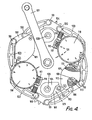
- variable diameter sprocket illustrated in Figures 3,4 and 5 comprises a rotary disc 101, carrying six bell-crank levers 102, each mounted on a pivot spindle 108, with axis P, the disc also being rigidly secured to the crank 107.
- Each lever arm 102 carries a contact element for engagement with the chain 10, two of these elements having teeth 104, while the other four elements 105 are smooth.
- the arms 102 pivot the contact elements move radially in and out, thus altering the effective diameter of the sprocket.
- the smooth elements 105 merely contribute to the effective diameter of the sprocket, but do not apply tension to the chain.
- the arms 102 are caused to pivot in unison by six interconnecting links 103, pivotally connected to the six arms respectively at pivots 99,100 at opposite ends of each link. It will be seen that each link 103 with the respective two arms 102 forms a parallelogram linkage via the adjacent two pivots P, which are spaced apart by the same distance as the length of the link 103. This maintains exactly equal pivoting movement of all the arms, and ensures that the contact elements are always at the same radial distance from the rotary axis 20 of the disc.
- the varying tension in the chain 10 not only applies a force to the toothed elements l04 but also causes a radial inward force acting on all the elements.
- the sprockets exhibit no internal friction, if a simple spring acting outwardly is used to resist the rapidly varying inward radial force, it is necessary to "lock" the radial movement of the contact elements over the sectors of rotation where the spring would overcome the inward radial force, or when the radial force acts outwardly, otherwise the sprocket would repeatedly expand and contract at every revolution.
- Figure 2 shows the cyclic changes in the turning "moment" exerted on each pivoted arm 102 about its pivot axis P, for five different effective sprocket diameters D 1 to D 5 , taking into account the cyclic changes in chain tension, and illustrates graphically the need for "locking" of the contact elements, whenever the outward spring force S exceeds the radial force represented by the graph R.
- the sectors L where locking is required may be.reduced by incorporating a one-way brake which exerts radial force B in parallel with and greater than the spring force S.
- the one-way brake resists movement of the contact elements inwards, but does not oppose outward movement and expansion of the sprocket diameter.
- Cyclists of different strengths will create different inward radial forces and it is important that the mechanism should provide adjustment of the resisting force.
- the design of the contact elements 104,105, both toothed and smooth, fixed on the ends of the arms 102, is very economical in manufacture and allows the effective diameter of the sprocket to contract to a small radius and also contributes to a nearly circular sprocket profile, particularly at minimum diameter. If the upper and lower "runs" of the transmission chain 10 are approximately parallel, the arrangement provides two "locked sectors" of approximately 60° rotation of the sprocket over which both toothed arms 104 engage with the chain 10 simultaneously, thereby effectively locking any possible wheel expansion.
- the locking sectors can be enlarged to 90° sectors by causing the chain to wrap around a larger part of the circumference of the sprocket. This may be achieved by locating the tensioning sprockets 16,17 closer to the variable sprocket 12 as shown in Figure 1.
- the mechanism also includes two spring units 109 and two one-way brake units 110 acting directly on the pivot spindles P of the arms 102 and hence influencing the radial positions of the contact elements 104,105.
- Each spring unit consists of a spiral spring 111 hooked at one end to a stop on a case 112 fixed rigidly to the disc 101. The other end of the spring is hooked onto a lug 113 secured to the adjacent pivot spindle P of one of the pivoting arms.
- There are two such spring units 108 symmetrically positioned, and thus creating a substantially constant outward radial spring force on all six contact elements.
- Each of the two one-way brake units 110 comprises a drum 114 (see Figure 5) secured to the respective spindle P so as to pivot with the attached arm 102.
- a one-way roller clutch or freewheel 115 connects the drum 114 to a male cone 116 when the arm 102 turns in a direction to reduce the diameter of the sprocket.
- the clutch 115 freewheels when the sprocket expands.
- the male cone 116 is adjustably pressed into a female cone 117 by means of a resilient cap 118 screwed onto the cone 117 which is itself held rigidly onto the disc 101, by means of a bolt 120.
- a lining 121 made of special friction material is incorporated into the female cone 117.
- the angular position of the cap 118 may be adjusted by means of a worm gear 119 with an adjusting knob. Adjustment of the worm gear 119 varies the engaging pressure between the two cones 116,117,and so varies the effective radial braking force B exerted on the contact elements 104,105, quite independently of the spring force urging the contact elements outwards.
- the bicyclist Before using the bicycle, the bicyclist adjusts the level of pedal pressure required to cause contraction of the sprocket diameter by rotating the two worm gears 119. Graduations on each cap 118 display the angular position of the cap relative to the female cone 117, and-hence the amount of braking.
- the sprocket mechanism also incorporates an annular stop 122 ( Figure 3) which limits the inward pivotal movement of the arms 102 and limits the value of the twisting force to which the arms are subjected, thus preventing damage.
- an adjustable limiter 124 ( Figure 4) is provided to vary the maximum effective sprocket diameter, and thereby compensate for lengthening of the links as the chain wears.
- the limiter includes a lever fixed to the spindle 108 of one of the arms 102, and arranged to abut against an adjustable polygon stop 125 having sides at different radii, and adjustably mounted on a pivot pin attached to the disc 101.
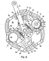
- the one-way brake is replaced by an automatic device to control the brake force in accordance with the force exerted on the crank 127.
- crank 127 is free to pivot through a small angle relative to the disc 101 about the axis of rotation 20.
- Each brake unit includes an inner drum 142 secured to the respective spindle pivot 108 of one of the arms 102, and a resilient housing 137 having a cylindrical wall 138 which surrounds the drum 142, with an interposed friction brake lining 141.
- the housing 137 is rigidly attached to the disc 101 and cannot rotate.
- the housing wall 138 which acts as the outer brake drum, is surrounded by a band 135, which exerts an adjustable grip, the ends of the band being pivotally connected to two toggle links 134,136,which are both connected at 132 to a tension link 133.
- the two links 133 are pivotally attached to a flange 126 fixed to the crank 127, so that small twisting movement of the crank in one direction relative to the disc 101 creates tension in the links 133, and thereby operates the toggle links to cause the band 135 to grip the outer brake drum 138.
- the torque applied by the crank is resisted by the natural resilience of the parts 133-136, so that increasing torque produces a small pivotal movement of the crank and generates an increasing brake force.
- the torque transmitted by the crank 127 is transferred to the disc 101 via the links 133, and the amount of braking may be adjusted by limiting the amount of crank torque transmitted in this way.It will also be seen that when the crank torque is reversed or falls below a predetermined value there will be no braking force,thus providing an effect somewhat similar to the one-way brake of Figures 3 and 4.
- the travel of the crank is limited by means of an adjustable stop which comprises a spring-loaded slider 145 having a sloping flank 144, and moveable along the crank 127, the flank being arranged to contact a pivoted cam 146 which is fixed to the spindle 108 of one of the pivoting arms 102.
- the brake linings 141 in the brake units of Figure 6 are, of course, liable to wear and as the linings become thinner certain problems may develop.
- the band 135 can close more tightly around the brake drums and the links 134,136,133, can therefore extend, thus reducing the efficiency of the toggle linkage geometry 134,136 and also reducing the useful travel of the crank 127.
- This problem is obviated by an automatic wear compensator, as illustrated in Figure 8, combined with a pair of tension springs 148 ( Figure 6), each acting between one of the links 133 and a fixed pin. 149 attached to the disc 101. The springs thus tend to rotate each band 135 clockwise.
- the band 135 has six internal ramps 158 and the wall 138 of the housing 137 has six corresponding ramps 159. Therefore if the lining 141 wears and a small radial gap develops between the inner drum 142 and the lining 141, the band 135 will rotate clockwise under the springs 148 thus causing the band to tighten onto the drum. If the incline of the ramps 158,159 is correctly chosen this arrangement compensates for wear in the brake lining without affecting the operation of the brake.
- the springs 111 can cause difficulties. For example, if the bicycle is parked with the contact elements fully contracted and the springs fully stressed, there is a risk that the arms 102 may jump outwards if the mechanism moves away from the locked position. This could be dangerous and accordingly the mechanism also includes a hydraulic damper, as shown in Figure 6.
- One of the spindles 108 is attached to a hydraulic damper vane 157 movable in a sextant casing 156, the casing being filled with a viscous silicone fluid and the vane being arranged to provide a controlled clearance, which allows pivotal movement of the spindle 108 at a controlled rate.
- the housing 137 also encloses a detent system ( Figure 7) which tends to bias the effective diameter of the sprocket to the values which correspond to whole numbers of effective teeth.
- the detent system comprises a quadrant plate 152 having notches engaging with a pawl 153 pivotally mounted on a pin 154 attached to the disc 101, and engaged by a spring 155. This is the non-positive resilient detent system referred to above, which urges the mechanism into one of a series of preferential positions.
- Figures 9 and 10 illustrate another form of the invention having a hydraulic control system.
- there are two hydraulic modules 161 each pivotally attached to the disc 101 at one end by means of a pin 163, and having a piston rod 166 at the other end, which engages a lever arm 165 secured to the spindle 108 of one of the swinging arms 102.
- the piston rod therefore either maintains or expands the sprocket diameter or resists contraction of the sprocket.
- each hydraulic control module 161 comprises a common housing 175 containing a cylinder 171, an adjustable relief vaive 173, and a gas accumulator 174.
- the rod 166 is connected to a piston 160, arranged to displace fluid from the cylinder 171 into a cross passage 176.
- the relief valve 173 opens and oil flows to the accumulator 174 through the port 177.
- the piston 160 moves down the cylinder 171 and the effective diameter of the sprocket contracts.
- the relief valve pressure is a function of both the gas-oil pressure in the accumulator 174 and the setting of the spring 178, which may be adjusted by means of a screw 181.
- the value of the pressure setting is displayed on the hydraulic housing 175 by means of a slider 182 working jointly with a scale 183 (see Figure 9).
- the hydraulic module as described differs fundamentally from a simple hydraulic dynamic damper.
- the relief valve 173 only opens when the pressure differential exceeds a datum level, and thus tends to prevent the piston moving from its instantaneous position.
- the check valve 172 set at a very low pressure, opens immediately allowing relatively free reverse movement.
- the resilient means acting outwardly on the contact elements are conveniently adjustable, to accommodate riders of different strength.
- the gas-oil accummulator may be adjusted, for example, by supplying or removing gas under pressure through the filling valve 184.
- the adjustment can be achieved by turning the whole case 112 and fixing it in a new angular position on the disc 101. It will be seen that the design of the sprocket also provides an automatic control of sprocket diameter in accordance with changes in the rotary speed of the disc 101.
- each of the arms 102 is displaced from the centre of gravity of the arm and the centrifugal force on each arm tends to throw the contact element 104,105 outwards to increase the effective diameter. This effect is more pronounced of course in high-speed industrial transmissions.
Landscapes
- Engineering & Computer Science (AREA)
- Mechanical Engineering (AREA)
- General Engineering & Computer Science (AREA)
- Chemical & Material Sciences (AREA)
- Combustion & Propulsion (AREA)
- Transportation (AREA)
- Transmissions By Endless Flexible Members (AREA)
- Devices For Conveying Motion By Means Of Endless Flexible Members (AREA)
- Transmission Devices (AREA)
- Control Of Transmission Device (AREA)
Applications Claiming Priority (2)
| Application Number | Priority Date | Filing Date | Title |
|---|---|---|---|
| GB8235574 | 1982-12-14 | ||
| GB8235574 | 1982-12-14 |
Publications (1)
| Publication Number | Publication Date |
|---|---|
| EP0112112A1 true EP0112112A1 (en) | 1984-06-27 |
Family
ID=10534961
Family Applications (1)
| Application Number | Title | Priority Date | Filing Date |
|---|---|---|---|
| EP83307387A Ceased EP0112112A1 (en) | 1982-12-14 | 1983-12-06 | Variable ratio transmission |
Country Status (7)
| Country | Link |
|---|---|
| US (1) | US4618331A (es) |
| EP (1) | EP0112112A1 (es) |
| JP (1) | JPS59121245A (es) |
| KR (1) | KR840006945A (es) |
| AU (1) | AU2235583A (es) |
| ES (1) | ES528004A0 (es) |
| ZA (1) | ZA839223B (es) |
Cited By (8)
| Publication number | Priority date | Publication date | Assignee | Title |
|---|---|---|---|---|
| US4836046A (en) * | 1987-05-04 | 1989-06-06 | Chappel Gilmore H | Automatic bicycle transmission |
| WO1995001277A1 (de) * | 1993-06-29 | 1995-01-12 | Jaroslaw Piotr Warszewski | Stufenlos selbsttätig verstellbarer fahrradantrieb |
| US5772546A (en) * | 1993-06-29 | 1998-06-30 | Warszewski; Jaroslaw Piotr | Continuously variable automatic drive |
| WO1999036710A1 (en) * | 1998-01-15 | 1999-07-22 | Tae Hoon Kim | Continuously variable transmission and method of changing speed using the same |
| WO2012169796A2 (ko) * | 2011-06-07 | 2012-12-13 | Cho Youngsang | 무단변속형 체인 전동장치 |
| WO2014105096A1 (en) | 2012-12-28 | 2014-07-03 | Promptlink Communications, Inc. | Video quality analysis and detection of blockiness artifacts and color variation |
| IT201700035616A1 (it) * | 2017-03-31 | 2018-10-01 | Bycly S R L | Trasmissione automatica per bicicletta |
| IT201700035600A1 (it) * | 2017-03-31 | 2018-10-01 | Bycly S R L | Trasmissione automatica per bicicletta |
Families Citing this family (14)
| Publication number | Priority date | Publication date | Assignee | Title |
|---|---|---|---|---|
| DE4318648C1 (de) * | 1993-06-04 | 1994-07-14 | Kraemer Hubert Dipl Ing Fh | Riementrieb mit selbttätiger stufenloser Übersetzungsänderung, insbesondere für Fahrräder |
| LT3943B (en) | 1993-12-23 | 1996-05-27 | Ciba Geigy Ag | Remedy for cultured plants protection, use of sulphamoyl-phenyl-carbamides for cultured plant protection, herbicidal preparation, process for preparing sulphamoyl-phenyl-carbamides |
| ES2125122B1 (es) * | 1994-10-28 | 1999-10-16 | Rodriguez Jose Antonio Tovar | Sistema de transmision auto-adaptable del par fuerza-velocidad para vehiculos. |
| US5655982A (en) * | 1995-06-16 | 1997-08-12 | Fyfe; Scott A. | Hydraulic shifting system for rider propelled vehicle |
| US6432009B1 (en) | 1998-08-06 | 2002-08-13 | Brigham Young University | Continuously variable transmission |
| US6332852B1 (en) | 2000-05-30 | 2001-12-25 | 3561020 Canada Inc. | Variable ratio drive system |
| WO2003078869A1 (en) | 2002-03-18 | 2003-09-25 | Johannes Jacobus Naude | Variable sprocket ivt machine |
| US7713153B2 (en) * | 2003-10-13 | 2010-05-11 | Varibox Ip (Pty) Limited | Infinitely variable transmission |
| US8393984B2 (en) * | 2003-10-13 | 2013-03-12 | Varibox (Pty) Limited | Infinitely variable transmission |
| DE602004006006T2 (de) | 2003-10-13 | 2008-01-03 | Varibox (Pty.) Ltd. | Stufenloses getriebe |
| US9139169B2 (en) * | 2006-08-18 | 2015-09-22 | Dura Operating Llc | Release mechanism for a parking brake clutch |
| US20110059821A1 (en) * | 2009-09-08 | 2011-03-10 | Vmt Technologies, Llc | Infinitely variable transmission |
| US9188205B2 (en) * | 2009-09-08 | 2015-11-17 | Gary D. Lee | Moon gear assembly |
| CN112594343B (zh) * | 2020-12-07 | 2022-08-09 | 南京昱晟机器人科技有限公司 | 差速传动设备 |
Citations (5)
| Publication number | Priority date | Publication date | Assignee | Title |
|---|---|---|---|---|
| FR653449A (fr) * | 1928-04-26 | 1929-03-21 | Changement de vitesses automatique | |
| DE6926728U (de) * | 1969-07-03 | 1971-03-18 | Koltze Ruediger | Fahrradgetriebe mit veraenderlicher uebersetsung |
| US3969948A (en) * | 1975-08-25 | 1976-07-20 | Pipenhagen Jr Charles A | Automatic bicycle transmission |
| WO1980002129A1 (en) * | 1979-04-10 | 1980-10-16 | Haagsche Smederij Constructiew | Sprocket wheel assembly for a chain transmission in particular adapted to bicycles |
| GB2062142A (en) * | 1979-10-29 | 1981-05-20 | Deal M | Variable diameter transmission wheel |
Family Cites Families (4)
| Publication number | Priority date | Publication date | Assignee | Title |
|---|---|---|---|---|
| US1092098A (en) * | 1912-08-13 | 1914-03-31 | Jeremiah C Fitzgerald | Pulley. |
| US3798989A (en) * | 1972-07-10 | 1974-03-26 | Tokheim Corp | Multiple speed drive transmission |
| DE3137018A1 (de) * | 1981-09-17 | 1983-04-07 | Alois 6833 Fraxern Kathan | Stufenloses riemengetriebe |
| US4478594A (en) * | 1982-05-10 | 1984-10-23 | Dayco Corporation | Belt tensioning means |
-
1983
- 1983-12-06 EP EP83307387A patent/EP0112112A1/en not_active Ceased
- 1983-12-13 ZA ZA839223A patent/ZA839223B/xx unknown
- 1983-12-13 ES ES528004A patent/ES528004A0/es active Granted
- 1983-12-13 AU AU22355/83A patent/AU2235583A/en not_active Abandoned
- 1983-12-14 JP JP58236006A patent/JPS59121245A/ja active Pending
- 1983-12-14 US US06/561,204 patent/US4618331A/en not_active Expired - Fee Related
- 1983-12-14 KR KR1019830005933A patent/KR840006945A/ko not_active Application Discontinuation
Patent Citations (5)
| Publication number | Priority date | Publication date | Assignee | Title |
|---|---|---|---|---|
| FR653449A (fr) * | 1928-04-26 | 1929-03-21 | Changement de vitesses automatique | |
| DE6926728U (de) * | 1969-07-03 | 1971-03-18 | Koltze Ruediger | Fahrradgetriebe mit veraenderlicher uebersetsung |
| US3969948A (en) * | 1975-08-25 | 1976-07-20 | Pipenhagen Jr Charles A | Automatic bicycle transmission |
| WO1980002129A1 (en) * | 1979-04-10 | 1980-10-16 | Haagsche Smederij Constructiew | Sprocket wheel assembly for a chain transmission in particular adapted to bicycles |
| GB2062142A (en) * | 1979-10-29 | 1981-05-20 | Deal M | Variable diameter transmission wheel |
Non-Patent Citations (1)
| Title |
|---|
| ENGINEERING, September 1983 "Developing drives on bicycles", page 656 * |
Cited By (10)
| Publication number | Priority date | Publication date | Assignee | Title |
|---|---|---|---|---|
| US4836046A (en) * | 1987-05-04 | 1989-06-06 | Chappel Gilmore H | Automatic bicycle transmission |
| WO1995001277A1 (de) * | 1993-06-29 | 1995-01-12 | Jaroslaw Piotr Warszewski | Stufenlos selbsttätig verstellbarer fahrradantrieb |
| US5772546A (en) * | 1993-06-29 | 1998-06-30 | Warszewski; Jaroslaw Piotr | Continuously variable automatic drive |
| WO1999036710A1 (en) * | 1998-01-15 | 1999-07-22 | Tae Hoon Kim | Continuously variable transmission and method of changing speed using the same |
| WO2012169796A2 (ko) * | 2011-06-07 | 2012-12-13 | Cho Youngsang | 무단변속형 체인 전동장치 |
| WO2012169796A3 (ko) * | 2011-06-07 | 2013-02-07 | Cho Youngsang | 무단변속형 체인 전동장치 |
| WO2014105096A1 (en) | 2012-12-28 | 2014-07-03 | Promptlink Communications, Inc. | Video quality analysis and detection of blockiness artifacts and color variation |
| IT201700035616A1 (it) * | 2017-03-31 | 2018-10-01 | Bycly S R L | Trasmissione automatica per bicicletta |
| IT201700035600A1 (it) * | 2017-03-31 | 2018-10-01 | Bycly S R L | Trasmissione automatica per bicicletta |
| WO2018178898A1 (en) * | 2017-03-31 | 2018-10-04 | Bycly S.R.L. | Automatic transmission for bicycles |
Also Published As
| Publication number | Publication date |
|---|---|
| ZA839223B (en) | 1985-02-27 |
| AU2235583A (en) | 1984-06-21 |
| JPS59121245A (ja) | 1984-07-13 |
| ES8502771A1 (es) | 1985-01-16 |
| US4618331A (en) | 1986-10-21 |
| ES528004A0 (es) | 1985-01-16 |
| KR840006945A (ko) | 1984-12-04 |
Similar Documents
| Publication | Publication Date | Title |
|---|---|---|
| US4618331A (en) | Variable ratio transmission | |
| US3995508A (en) | Automatic bicycle transmission | |
| CN111703536B (zh) | 用于自行车部件的阻尼器 | |
| US4713042A (en) | Automatic transmission for a bicycle | |
| US7874955B2 (en) | Bicycle transmission system | |
| EP1980484B1 (en) | Mounting system for an internal bicycle transmission | |
| CA1077743A (en) | Stepless, variable stroke drive having a non-rotating cam | |
| US4701152A (en) | Automatic transmission for multi-speed bicycle | |
| EP0615587B1 (en) | Automatic transmission for multi-speed bicycle | |
| AU774149B2 (en) | Continuously variable transmission | |
| US4598920A (en) | Automatic transmission for a bicycle and the like-pedaled apparatus | |
| GB2062142A (en) | Variable diameter transmission wheel | |
| EP4149830A1 (en) | Bicycle drivetrain | |
| EP0310617B1 (en) | Automatic variable transmission for vehicles | |
| US4277986A (en) | Stepless, variable stroke drive having a non-rotating cam | |
| EP0380828A1 (en) | Power transmission apparatus | |
| US6432009B1 (en) | Continuously variable transmission | |
| US4098147A (en) | Waddington drive having a cam actuated by an integral flyweight | |
| DE102016008839B3 (de) | Stufenlose mechanische Getriebevorrichtung mit drehmomentabhängiger Veränderung des Übersetzungsverhältnisses für formschlüssige Kraftübertragungen. | |
| EP0261139B1 (en) | Continuous speed gear functioning by means of cog wheels with cogs of variable radius | |
| US4124107A (en) | Multistage freewheel for bicycles | |
| US3388617A (en) | Automatic variable speed bicycle transmission | |
| US5165510A (en) | Centrifugal friction clutch | |
| US5597056A (en) | Torque controlled infinite ratio friction drive hub | |
| US6007441A (en) | Automatic gear shifting mechanism for multi-speed manually powered vehicles |
Legal Events
| Date | Code | Title | Description |
|---|---|---|---|
| PUAI | Public reference made under article 153(3) epc to a published international application that has entered the european phase |
Free format text: ORIGINAL CODE: 0009012 |
|
| AK | Designated contracting states |
Designated state(s): AT BE CH DE FR GB IT LI LU NL SE |
|
| 17P | Request for examination filed |
Effective date: 19841109 |
|
| 17Q | First examination report despatched |
Effective date: 19860127 |
|
| STAA | Information on the status of an ep patent application or granted ep patent |
Free format text: STATUS: THE APPLICATION HAS BEEN REFUSED |
|
| 18R | Application refused |
Effective date: 19880319 |