EP0111969B1 - Filter device - Google Patents
Filter device Download PDFInfo
- Publication number
- EP0111969B1 EP0111969B1 EP83201764A EP83201764A EP0111969B1 EP 0111969 B1 EP0111969 B1 EP 0111969B1 EP 83201764 A EP83201764 A EP 83201764A EP 83201764 A EP83201764 A EP 83201764A EP 0111969 B1 EP0111969 B1 EP 0111969B1
- Authority
- EP
- European Patent Office
- Prior art keywords
- filter device
- valve
- housing
- arm
- coffee
- Prior art date
- Legal status (The legal status is an assumption and is not a legal conclusion. Google has not performed a legal analysis and makes no representation as to the accuracy of the status listed.)
- Expired
Links
Images


Classifications
-
- A—HUMAN NECESSITIES
- A47—FURNITURE; DOMESTIC ARTICLES OR APPLIANCES; COFFEE MILLS; SPICE MILLS; SUCTION CLEANERS IN GENERAL
- A47J—KITCHEN EQUIPMENT; COFFEE MILLS; SPICE MILLS; APPARATUS FOR MAKING BEVERAGES
- A47J31/00—Apparatus for making beverages
- A47J31/06—Filters or strainers for coffee or tea makers ; Holders therefor
- A47J31/0605—Filters or strainers for coffee or tea makers ; Holders therefor with a valve at the filter-outlet; Anti-drip devices
- A47J31/061—Filters or strainers for coffee or tea makers ; Holders therefor with a valve at the filter-outlet; Anti-drip devices activated by the beverage container
-
- A—HUMAN NECESSITIES
- A47—FURNITURE; DOMESTIC ARTICLES OR APPLIANCES; COFFEE MILLS; SPICE MILLS; SUCTION CLEANERS IN GENERAL
- A47J—KITCHEN EQUIPMENT; COFFEE MILLS; SPICE MILLS; APPARATUS FOR MAKING BEVERAGES
- A47J31/00—Apparatus for making beverages
- A47J31/06—Filters or strainers for coffee or tea makers ; Holders therefor
- A47J31/0621—Filters or strainers for coffee or tea makers ; Holders therefor with means for varying the infusion outflow velocity, e.g. for brewing smaller quantities
Definitions
- the invention relates to a filter device for, for example, a coffee machine with a housing, in the bottom area of which there is only one outflow opening, the size of which can be regulated by means of a manually operated adjusting mechanism, which adjusting mechanism is rotatably arranged in the housing of the filter device and a protruding from the housing of the filter device, is assigned to a slidable actuating button in a slot of the housing, with which the lifting height of the valve can be regulated.
- Such a filter device is known from DE-A-26 25 650.
- the water can only touch the ground coffee for a short time. The consequence of this is that the coffee extract is not optimal in terms of quality.
- a longer contact of the hot water with the ground coffee can be achieved through a smaller outflow opening of the filter device.
- the contact of the hot water with the ground coffee will be too long when preparing large amounts of coffee, which means that the quality of the coffee extract is again not optimal.
- Such a controllable filter device is shown in the aforementioned DE-A-26 25 650.
- the outflow opening can also be closed in the aforementioned DE-A-26 25 650.
- the valve is carried by means of elastic webs in a sealing collar arranged below the filter housing.
- the size of the outflow opening is regulated by twisting or shifting the sealing collar and thus the valve relative to the outflow opening.
- the valve is not under the spring pressure of the elastic webs until the outflow opening is closed.
- the adjustment mechanism comprises a bayonet-type guide between the closure sleeve and the filter housing.
- a vertical displacement of the sealing collar is achieved by means of an actuating cam mounted in the coffee machine housing with an actuating arm.
- the invention has for its object to provide a construction with which the valve can be reliably controlled for regulating the size of the outflow opening and for closing off the outflow opening.
- the filter device is characterized in a first embodiment by the fact that the adjustment mechanism is formed by an arm, a part of the arm which is located under the valve being provided with support surfaces at different levels, between which oblique run-up surfaces extend, which support surfaces work with a valve lifter of the valve.
- the closing of the outflow opening is effected by the actuation button, the valve keeping the outflow opening closed by the force of the resilient element.
- a second embodiment of the filter device according to the invention is characterized in that a pin which protrudes from the housing of the filter device and is coupled by means of an arm which can be rotated in the housing of the filter device is coupled to the valve, the arm being on a Side of the fulcrum connected to the valve and coupled to the pin on the other side of the fulcrum by means of the second resilient element, and the pin can be pressed in by a coffee pot which can be placed under the filter device in such a way that the outflow opening is released from the valve in a coffee pot placed underneath and when the coffee pot is removed, the outflow opening is closed by the valve and that the adjustment mechanism is formed by a slide which is provided with support surfaces at different levels, between which an inclined run-up surface extends Which support areas are effective as stops for the arm.
- the outflow opening is always closed automatically after the coffee pot is removed, regardless of the size of the outflow opening set by the adjusting mechanism.
- a coffee machine is known per se from CH-A-616 064, in which a rotatable, spring-loaded rocker is provided below a coffee filter to close the outflow opening when the filter is removed. the pitcher.
- the filter device according to the invention is preferably provided with an overflow opening.
- the housing of the filter device 1 is formed by a conical part 2 for receiving a filter bag, a cylindrical part 3 and a second shorter cylindrical part 4 concentrically around the same.
- the second cylindrical part 4 is supported on the edge 6 of the coffee pot.
- In the bottom of the conical part 2 there is only one outflow opening 7, in which a valve 8 is arranged.
- the valve has a valve body 9, which consists of a valve disk 10 and a valve stem 11, on which there are four radially extending wings 12, an elastic sealing ring 13 and a spring 14. In the closed position of the outflow opening, the sealing ring lies on the edge 15 of the outflow opening .
- the manually operable adjustment mechanism 16 includes an arm 17, one end of which is attached to an actuation button 18.
- the actuation button protrudes through slots 19 and 20 in the housing parts 3 and 4, respectively.
- the other end of the arm is rotatable about a point 21 in the floor.
- a portion 22 of the arm extends from the fulcrum towards the arm.
- This part there is an opening 23, a circular arc-shaped edge part 24 of the opening which is furthest from the pivot point 21 being located under the valve stem 11.
- This circular arc-shaped edge part is provided on the side facing the valve stem with support surfaces 25, 26, 27 at different levels, between which oblique run-up surfaces 28, 29 extend and which support surfaces cooperate with the valve stem 11.
- the edge part 24 has a low-lying support surface 25, a middle support surface 26 and a high-lying support surface 27. If the low-lying support surface 25 is below the valve stem 11, the valve closes the outflow opening completely and no drops can leak out of the filter device . If the middle support surface 26 is located below the valve stem (the position shown in FIG. 4), the valve is raised to such an extent that an annular opening 30 is formed between the edge 15 of the outflow opening 7 and the valve disk 10 of the valve body. The size of this annular opening determines the flow rate of the coffee extract that flows out of the filter device. This position is meant for preparing a small number of cups of coffee. If the high support surface is under the valve stem, the valve is raised even further and a large outflow opening is free. This position is best used when preparing a large number of cups of coffee. The respective positions can be obtained by moving the operating button 18 to the left or right.
- the circular arc-shaped edge part 24 has a small thickness in order to impair the outflow of the coffee extract as little as possible.
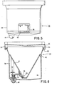
- FIG. 5 to 8 another filter device according to the invention is shown.
- This filter device 33 hangs in an overhanging arm 34 of a coffee machine, not shown.
- the housing of the filter device has cams 35 which are supported on an edge 36 of the arm 34.
- the filter device can be easily removed from the arm for cleaning and filling.
- the housing of the filter device 34 is formed by a conical part 37, specifically for receiving a filter bag and by a cylindrical part 38 lying around this part. In the bottom region of the conical part there is only one outflow opening 39 with a valve 40.
- An arm 41 is in the housing of the filter device rotatably mounted.
- the arm has a cam 43 which can rotate in a cavity 43 of the conical part 37.
- the valve On one side of the fulcrum is the valve, which forms a whole with this part of the arm.
- a leaf spring 44 which is clamped in the housing on one side, presses with the other side against the arm 41, as a result of which the valve 40 is pressed in the direction of the closed position of the outflow opening.
- the arm On the other side of the fulcrum, the arm is coupled by means of a second spring 45 to a pin 46 which is displaceable in the bottom 47 of the cylindrical part 38. In the bottom 47 there is a large passage opening 48.
- the spring 45 is enclosed between the hollow pin 46 and a bush 49 which is displaceable in the hollow pin.
- the arm 41 supports against the upper edge of the sleeve.
- the pin 46 protrudes with the spherical underside below the bottom part 47 of the cylindrical part 38 and can be pressed in by a coffee pot which can be placed under the filter device. If you place a coffee pot under the filter device, the pin 46 is pressed in by the edge of the coffee pot against the spring force of the second spring 45, whereby the arm rotates about the pivot point (cavity 43) and the valve opens the outflow opening. When turned on When the pin is pressed, the spring force of the second spring 45 is greater than that of the leaf spring 44.
- the second spring presses the pin down, as a result of which the spring force is reduced and less than the spring force of the leaf spring 44, as a result of which the leaf spring presses the valve with the elastic ring 50 against the edge 51 of the outflow opening and closes it completely. Dripping after the coffee pot has been removed is no longer possible.
- the adjustment mechanism 52 is formed by an arcuate slider 53 (Fig. 8), one end of which through a slot 54 in the. protrudes cylindrical housing part 38 of the filter device and to which an actuating button 55 is attached.
- the slide is provided on the underside with two support surfaces 56 and 57 at different levels, between which there is an inclined run-up surface 58.
- the two support surfaces each serve as a stop for the arm.
- the annular opening 60 between the cylindrical part 59 and the inner wall 61 of the outflow opening then essentially determines the actual passage opening and consequently the amount of coffee extract that flows out of the filter device.
- This position is meant for preparing a small number of cups of coffee. If the support surface 57 is opposite the arm 41, the angle of rotation of the arm is larger and the whole cylindrical part 59 of the valve will be outside the edge of the outflow opening. The real passage is now much larger. This position is meant for preparing a large number of cups of coffee.
Description
Die Erfindung bezieht sich auf eine Filtervorrichtung für beispielsweise einen Kaffeeautomaten mit einem Gehäuse, in dessen Bodenbereich sich nur eine Ausströmungsöffnung befindet, deren Größe mittels eines handbetätigbaren Einstellmechanismus regelbar ist, welcher Einstellmechanismus drehbar im Gehäuse der Filtervorrichtung angeordnet und einem aus dem Gehäuse der Filtervorrichtung herausragenden, in einem Schlitz des Gehäuses verschiebbaren Betätigungsknopf zugeordnet ist, womit die Hubhöhe des Ventils regelbar ist.The invention relates to a filter device for, for example, a coffee machine with a housing, in the bottom area of which there is only one outflow opening, the size of which can be regulated by means of a manually operated adjusting mechanism, which adjusting mechanism is rotatably arranged in the housing of the filter device and a protruding from the housing of the filter device, is assigned to a slidable actuating button in a slot of the housing, with which the lifting height of the valve can be regulated.
Eine derartige Filtervorrichtung ist aus der DE-A-26 25 650 bekannt. Beim Zubereiten geringer Kaffeemengen, wofür eine entsprechend geringe Wassermenge notwendig ist, kann das Wasser nur während kurzer Zeit den Kaffeemehl berühren. Die Folge davon ist, daß der Kaffee-Extrakt qualitativ nicht optimal ist. Ein längerer Kontakt des heißen Wassers mit dem Kaffeemehl läßt sich durch eine kleinere Ausströmungsöffnung der Filtervorrichtung erzielen. Dadurch wird jedoch beim Zubereiten großer Kaffeemengen der Kontakt des heißen Wassers mit dem Kaffeemehl zu lange sein, wodurch der Kaffee-Extrakt qualitativ dann wieder nicht optimal ist. Dies führt zu dem Wunsch, die Durchlaufgeschwindigkeit des Kaffee-Extraktes durch die Filtervorrichtung abhängig von der Anzahl zuzubereitender Tassen regelbar zu machen. In der obengenannten DE-A-26 25 650 ist eine derartige regelbare Filtervorrichtung dargestellt.Such a filter device is known from DE-A-26 25 650. When preparing small amounts of coffee, which requires a correspondingly small amount of water, the water can only touch the ground coffee for a short time. The consequence of this is that the coffee extract is not optimal in terms of quality. A longer contact of the hot water with the ground coffee can be achieved through a smaller outflow opening of the filter device. As a result, however, the contact of the hot water with the ground coffee will be too long when preparing large amounts of coffee, which means that the quality of the coffee extract is again not optimal. This leads to the desire to make the throughput speed of the coffee extract through the filter device adjustable depending on the number of cups to be prepared. Such a controllable filter device is shown in the aforementioned DE-A-26 25 650.
Es ist zugleich erwünscht, die Ausströmungsöffnung völlig abschließbar zu machen um zu vermeiden, daß nach dem Zubereiten von Kaffee und bei entfernter Kaffeekanne, Kaffee-Extrakttropfen aus der Filtervorrichtung herauslecken,-die eine darunter liegende Wärmeplatte verschmutzen können. Auch bei der genannten DE-A-26 25 650 ist die Ausströmungsöffnung abschließbar. Das Ventil ist dabei mittels elastischer Stege in einer unterhalb des Filtergehäuses angeordneten Verschlußmanschette getragen. Die Regelung der Größe der Ausströmungsöffnung erfolgt durch Verdrehung oder Verschiebung der Verschlußmanschette und damit des Ventils gegenüber der Ausströmungsöffnung. Erst beim Abschließen der Ausströmungsöffnung steht das Ventil unter dem Federdruck der elastischen Stege. Zum Verdrehen der Verschlußmanschette umfaßt der Einstellmechanismus eine bajonettverschlußartige Führung zwischen der Verschlußmanschette und dem Filtergehäuse. In einer alternativen Konstruktion wird eine vertikale Verschiebung der Verschlußmanschette erreicht mittels eines im Kaffeemaschinengehäuse gelagerten Stellnockens mit einem Stellarm.At the same time, it is desirable to make the outflow opening completely lockable in order to prevent coffee extract drops from leaking out of the filter device after making coffee and with the coffee pot removed, which can contaminate an underlying heating plate. The outflow opening can also be closed in the aforementioned DE-A-26 25 650. The valve is carried by means of elastic webs in a sealing collar arranged below the filter housing. The size of the outflow opening is regulated by twisting or shifting the sealing collar and thus the valve relative to the outflow opening. The valve is not under the spring pressure of the elastic webs until the outflow opening is closed. To rotate the closure sleeve, the adjustment mechanism comprises a bayonet-type guide between the closure sleeve and the filter housing. In an alternative construction, a vertical displacement of the sealing collar is achieved by means of an actuating cam mounted in the coffee machine housing with an actuating arm.
Der Erfindung liegt die Aufgabe zugrunde, eine Konstruktion zu schaffen, mit der das Ventil zuverlässig gesteuert werden kann zum Regeln der Größe der Ausströmungsöffnung und zum Abschließen der Ausströmungsöffnung.The invention has for its object to provide a construction with which the valve can be reliably controlled for regulating the size of the outflow opening and for closing off the outflow opening.
Die erfindungsgemäße Filtervorrichtung weist dazu in einer ersten Ausführungsform das Kennzeichnen auf, daß der Einstellmechanismus durch einen Arm gebildet ist, wobei ein Teil des Arms, der sich unter dem Ventil befindet, mit Unterstützungsflächen auf unterschiedlichen Pegeln versehen ist, zwischen denen sich schräge Auflaufflächen erstrecken, welche Unterstützungsflächen mit einem Ventilstößel des Ventils zusammenarbeiten.To this end, the filter device according to the invention is characterized in a first embodiment by the fact that the adjustment mechanism is formed by an arm, a part of the arm which is located under the valve being provided with support surfaces at different levels, between which oblique run-up surfaces extend, which support surfaces work with a valve lifter of the valve.
Das Abschließen der Ausströmungsöffnung wird bei dieser Ausführungsform vom Betätigungsknopf bewirkt, wobei das Ventil durch die Kraft des federnden Elementes die Ausströmungsöffnung geschlossen hält.In this embodiment, the closing of the outflow opening is effected by the actuation button, the valve keeping the outflow opening closed by the force of the resilient element.
Eine zweite Ausführungsform der erfindungsgemäßen Filtervorrichtung weist das Kennzeichen auf, daß ein durch ein zweites federndes Element beanspruchter unter dem Gehäuse der Filtervorrichtung herausragender Stift vorgesehen ist, der mittels eines in dem Gehäuse der Filtervorrichtung drehbaren Armes mit dem Ventil gekuppelt ist, wobei der Arm auf einer Seite des Drehpunktes mit dem Ventil verbunden und auf der anderen Seite des Drehpunktes mittels des zweiten federnden Elementes mit dem Stift gekuppelt ist, und der Stift durch eine unter die Filtervorrichtung stellbare Kaffeekanne derart eindrückbar ist, daß bei einer daruntergestellten Kaffeekanne die Ausströmungsöffnung von dem Ventil freigegeben ist und bei einer entfernten Kaffeekanne die Ausströmungsöffnung von dem Ventil geschlossen wird, und daß der Einstellmechanismus durch einen Schieber gebildet wird, der mit Unterstützungsflächen auf unterschiedlichen Pegeln versehen ist, zwischen denen sich eine schräge Auflauffläche erstreckt, welche Unterstützungsflächen als Anschläge für den Arm wirksam sind.A second embodiment of the filter device according to the invention is characterized in that a pin which protrudes from the housing of the filter device and is coupled by means of an arm which can be rotated in the housing of the filter device is coupled to the valve, the arm being on a Side of the fulcrum connected to the valve and coupled to the pin on the other side of the fulcrum by means of the second resilient element, and the pin can be pressed in by a coffee pot which can be placed under the filter device in such a way that the outflow opening is released from the valve in a coffee pot placed underneath and when the coffee pot is removed, the outflow opening is closed by the valve and that the adjustment mechanism is formed by a slide which is provided with support surfaces at different levels, between which an inclined run-up surface extends Which support areas are effective as stops for the arm.
Das Abschließen der Ausströmungsöffnung wird dabei immer automatisch bewirkt nach Wegziehen der Kaffeekanne, unabhängig von der vom Einstellmechanismus eingestellten Größe der Ausströmungsöffnung. Dabei sei bemerkt, daß an sich aus CH-A-616 064 eine Kaffeemaschine bekannt ist, in der unterhalb eines Kaffeefilters eine drehbare, federbelastete Wippe vorgesehen ist zum Verschließen der Ausströmungsöffnung beim Herausnehmen des Filters bezw. des Kruges.The outflow opening is always closed automatically after the coffee pot is removed, regardless of the size of the outflow opening set by the adjusting mechanism. It should be noted that a coffee machine is known per se from CH-A-616 064, in which a rotatable, spring-loaded rocker is provided below a coffee filter to close the outflow opening when the filter is removed. the pitcher.
Vorzugsweise ist die Filtervorrichtung nach der Erfindung mit einer Überlauföffnung versehen.The filter device according to the invention is preferably provided with an overflow opening.
Ausführungsbeispiele der Erfindung sind in der Zeichnung dargestellt und werden im folgenden näher beschrieben. Es zeigen:
- Fig. 1 eine schaubildliche Ansicht einer Filtervorrichtung,
- Fig. 2 einen Schnitt durch die Filtervorrichtung nach Fig. 1 gemäß der Linie 11-11,
- Fig. 3 eine Ansicht der Unterseite der Filtervorrichtung nach Fig. 1,
- Fig. 4 einen Schnitt in vergrößertem Maßstab durch die Filtervorrichtung nach Fig. 3 gemäß der Linie IV-IV,
- Fig. 5 eine schaubildliche Ansicht einer anderen Filtervorrichtung,
- Fig. 6 eine Ansicht der Filtervorrichtung nach Fig. 5,
- Fig. 7 einen teilweisen Schnitt durch die Filtervorrichtung nach Fig. 5 in vergrößertem Maßstab,
- Fig. 8 eine Ansicht des Schiebers für den Einstellmechanismus der Filtervorrichtung nach Fig. 5.
- 1 is a perspective view of a filter device,
- 2 shows a section through the filter device according to FIG. 1 along the line 11-11,
- 3 is a view of the underside of the filter device of FIG. 1,
- 4 shows a section on an enlarged scale through the filter device according to FIG. 3 along the line IV-IV,
- 5 is a perspective view of another filter device,
- 6 is a view of the filter device of FIG. 5,
- 7 is a partial section through the filter device of FIG. 5 on an enlarged scale,
- 8 is a view of the slide for the adjustment mechanism of the filter device of FIG .. 5
In den Figuren 1 bis 4 ist eine Filtervorrichtung dargestellt, die sich dazu eignet, auf eine Kaffeekanne gestellt zu werden. Das Gehäuse der Filtervorrichtung 1 wird durch einen kegelförmigen Teil 2 zum Aufnehmen einer Filtertüte, einen zylinderförmigen Teil 3 und einen zweiten konzentrisch um denselben liegenden kürzeren zylinderförmigen Teil 4 gebildet. Beim Aufstellen auf die Kaffeekanne 5 stützt der zweite zylinderförmige Teil 4 auf den Rand 6 der Kaffeekanne. In dem Boden des kegelförmigen Teils 2 befindet sich nur eine Ausströmungsöffnung 7, worin ein Ventil 8 angeordnet ist. Das Ventil hat einen Ventilkörper 9, der aus einer Ventilscheibe 10 und einem Ventilstiel 11 besteht, woran sich vier radial erstreckende Flügel 12 befinden, einen elastischen Dichtungsring 13 und eine Feder 14. In geschlossener Lage der Ausströmungsöffnung liegt der Dichtungsring auf dem Rand 15 der Ausströmungsöffnung. In geöffneter Lage kann der Kaffee-Extrakt zwischen die Flügel 12 hindurch in die Kaffeekanne strömen. Der handbetätigbare Einstellmechanismus 16 umfaßt einen Arm 17, von dem ein Ende an einem Betätigungsknopf 18 befestigt ist. Der Betätigungsknopf ragt durch Schlitze 19 und 20 in den Gehäuseteilen 3 bzw. 4 heraus. Das andere Ende des Arms ist um einen Punkt 21 in dem Boden drehbar. Ein Teil 22 des Arms erstreckt sich von dem Drehpunkt in Richtung quer zu dem Arm. In diesem Teil befindet sich eine Öffnung 23, wobei ein kreisbogenförmiger Randteil 24 der Öffnung, der am weitesten von dem Drehpunkt 21 liegt, sich unter dem Ventilstiel 11 befindet. Dieser kreisbogenförmige Randteil ist zu der Seite, die dem Ventilstiel zugewandt ist, mit Unterstützungsflächen 25, 26, 27 auf unterschiedlichen Pegeln versehen, zwischen denen sich schräge Auflaufflächen 28, 29 erstrecken und welche Unterstützungsflächen mit dem Ventilstiel 11 zusammenarbeiten. Der Randteil 24 hat eine niedrig liegende Unterstützungsfläche 25, eine mittlere Unterstützungsfläche 26 und eine hoch liegende Unterstützungsfläche 27. Befindet sich die niedrig liegende Unterstützungsfläche 25 unter dem Ventilstiel 11, so schließt das Ventil die Ausströmungsöffnung völlig ab und es können keine Tropfen aus der Filtervorrichtung weglecken. Befindet sich die mittlere Unterstützungsfläche 26 unter dem Ventilstiel (die in Fig. 4 dargestellte Lage), so wird das Ventil soweit gehoben, daß zwischen dem Rand 15 der Ausströmungsöffnung 7 und der Ventilscheibe 10 des Ventilkörpers eine ringförmige Öffnung 30 entsteht. Die Größe dieser ringförmigen Öffnung bestimmt die Durchströmungsgeschwindigkeit des Kaffee-Extraktes, das aus der Filtervorrichtung herausströmt. Diese Stellung ist gemeint zum Zubereiten einer geringen Anzahl Tassen Kaffee. Befindet sich die hoch liegende Unterstützungsfläche unter dem Ventilstiel, so wird das Ventil noch weiter gehoben und wird eine große Ausströmungsöffnung frei. Diese Stellung kann am besten benutzt werden beim Zubereiten einer größeren Anzahl Tassen Kaffee. Die jeweiligen Stellungen können durch eine Links- bzw. Rechtsverschiebung des Betätigungsknopfes 18 erhalten werden.1 to 4 show a filter device which is suitable for being placed on a coffee pot. The housing of the
Der kreisbogenförmige Randteil 24 hat eine geringe Dicke um die Ausströmung des Kaffee-Extraktes möglichst wenig zu beeinträchtigen.The circular arc-
Zwischen den zwei zylinderförmigen Teilen 3 und 4 des Gehäuses befindet sich noch eine Überlauföffnung 31. Wenn beim Zubereiten von Kaffee das Ventil aus Versehen geschlossen wird oder wenn man viel Kaffee zubereiten möchte und das Ventil befindet sich in der Stellung für eine kleine Ausströmungsöffnung, so kann der Kaffee-Extrakt über den Rand 33 des punktförmigen Teils 2 strömen und durch die Überlauföffnung 31 zwischen die zylinderförmigen Teile 3 und 4 hindurch in die Kaffeekanne 5 strömen.There is an overflow opening 31 between the two
In den Fig. 5 bis 8 ist eine andere Filtervorrichtung nach der Erfindung dargestellt. Diese Filtervorrichtung 33 hängt in einem überhängenden Arm 34 eines weiterhin nicht dargestellten Kaffee-Automaten. Das Gehäuse der Filtervorrichtung weist dazu Nocken 35 auf, die auf einen Rand 36 des Arms 34 stützen. Die Filtervorrichtung läßt sich auf einfache Weise aus dem Arm entfernen und zwar zum Reinigen und zum Füllen. Das Gehäuse der Filtervorrichtung 34 wird durch einen kegelförmigen Teil 37 gebildet und zwar zum Aufnehmen einer Filtertüte und durch einen um diesen Teil liegenden zylinderförmigen Teil 38. Im Bodenbereich des kegelförmigen Teils befindet sich nur eine Ausströmungsöffnung 39 mit einem Ventil 40. Ein Arm 41 ist in dem Gehäuse der Filtervorrichtung drehbar gelagert. Dazu weist der Arm einen Nocken 43 auf, der in einem Hohlraum 43 des kegelförmigen Teils 37 drehen kann. Auf der einen Seite des Drehpunktes befindet sich das Ventil, das mit diesem Teil des Arms ein Ganzes bildet. Eine Blattfeder 44, die auf einer Seite in dem Gehäuse festgeklemmt ist, drückt mit der anderen Seite gegen den Arm 41, wodurch das Ventil 40 in Richtung der geschlossenen Lage der Ausströmungsöffnung gedrückt wird. Auf der anderen Seite des Drehpunktes ist der Arm mittels einer zweiten Feder 45 mit einem Stift 46 gekuppelt, der in dem Boden 47 des zylinderförmigen Teils 38 verschiebbar ist. In dem Boden 47 befindet sich eine große Durchlaßöffnung 48. Die Feder 45 liegt zwischen dem Hohlsift 46 und einer in dem Hohlstift verschiebbaren Büchse 49 eingeschlossen. Gegen den oberen Rand der Büchse stützt der Arm 41. Der Stift 46 ragt mit der kugelförmigen Unterseite unter den Bodenteil 47 des zylinderförmigen Teils 38 heraus und ist durch eine unter die Filtervorrichtung stellbare Kaffeekanne eindrückbar. Stellt man eine Kaffeekanne unter die Filtervorrichtung, so wird der Stift 46 durch den Rand der Kaffeekanne entgegen der Federkraft der zweiten Feder 45 eingedrückt, wodurch der Arm um den Drehpunkt (Hohlraum 43) dreht und das Ventil die Ausströmungsöffnung öffnet. Bei eingedrücktem Stift ist die Federkraft der zweiten Feder 45 größer als die der Blattfeder 44. Nimmt man die Kaffeekanne unter der Filtervorrichtung weg, so drückt die zweite Feder den Stift nach unten, wodurch die Federkraft verringert und kleiner wird als die Federkraft der Blattfeder 44, wodurch die Blattfeder das Ventil mit dem elastischen Ring 50 gegen den Rand 51 der Ausströmungsöffnung drückt und diese völlig abschließt. Nachtropfen, nachdem die Kaffeekanne entfernt ist, ist dadurch nicht mehr möglich.5 to 8, another filter device according to the invention is shown. This
Der Einstellmechanismus 52 wird durch einen bogenförmigen Schieber 53 (Fig. 8) gebildet, dessen eines Ende durch einen Schlitz 54 in dem. zylinderförmigen Gehäuseteil 38 der Filtervorrichtung ragt und an dem ein Betätigungsknopf 55 befestigt ist. Der Schieber ist auf der Unterseite mit zwei Unterstützungsflächen 56 und 57 auf unterschiedlichen Pegeln versehen, zwischen denen sich eine schiefe Auflauffläche 58 befindet. Die zwei Unterstützungsflächen dienen je als Anschlag für den Arm. Wenn die Unterstützungsflächen 56 gegenüber dem Arm 41 gedreht ist, kann der Arm bei einer unter die Filtervorrichtung gestellten Kaffeekanne nur über einen geringfügigen Winkel drehen, wodurch das Ventil sich zwar öffnet, wobei jedoch ein zylinderförmiger Teil 59 des Ventils sich noch in der Ausströmungsöffnung 39 befindet. Die ringförmige Öffnung 60 zwischen dem zylinderförmigen Teil 59 und der Innenwand 61 der Ausströmungsöffnung bestimmt dann im wesentlichen die wirkliche Durchlaßöffnung und folglich die Menge Kaffee-Extrakt, die aus der Filtervorrichtung strömt. Diese Stellung ist gemeint zum Zubereiten einer geringen Anzahl Tassen Kaffee. Wenn die Unterstützungsfläche 57 sich gegenüber dem Arm 41 befindet, ist der Verdrehungswinkel des Arms größer und wird der ganze zylinderförmige Teil 59 des Ventils sich außerhalb des Randes der Ausströmungsöffnung befinden. Der wirkliche Durchgang ist nun viel größer. Diese Stellung ist gemeint zum Zubereiten einer größeren Anzahl Tassen Kaffee.The
Zwischen dem kegelförmigen Teil 37 und dem zylinderförmigen Teil 38 der Filtervorrichtung befindet sich ebenfalls eine Überlauföffnung 62.There is also an
Claims (4)
Applications Claiming Priority (2)
| Application Number | Priority Date | Filing Date | Title |
|---|---|---|---|
| DE8235364U | 1982-12-16 | ||
| DE19828235364U DE8235364U1 (en) | 1982-12-16 | 1982-12-16 | FILTER DEVICE |
Publications (2)
| Publication Number | Publication Date |
|---|---|
| EP0111969A1 EP0111969A1 (en) | 1984-06-27 |
| EP0111969B1 true EP0111969B1 (en) | 1989-03-22 |
Family
ID=6746570
Family Applications (1)
| Application Number | Title | Priority Date | Filing Date |
|---|---|---|---|
| EP83201764A Expired EP0111969B1 (en) | 1982-12-16 | 1983-12-14 | Filter device |
Country Status (3)
| Country | Link |
|---|---|
| EP (1) | EP0111969B1 (en) |
| DE (2) | DE8235364U1 (en) |
| FR (1) | FR2537863A1 (en) |
Cited By (1)
| Publication number | Priority date | Publication date | Assignee | Title |
|---|---|---|---|---|
| DE102015219196A1 (en) | 2015-10-05 | 2017-04-06 | BSH Hausgeräte GmbH | Coffeemaker |
Families Citing this family (10)
| Publication number | Priority date | Publication date | Assignee | Title |
|---|---|---|---|---|
| NL8800257A (en) * | 1988-02-03 | 1989-09-01 | Smitdesign Bv | ADJUSTABLE QUICK FILTER. |
| FR2704409B1 (en) * | 1993-04-30 | 1995-06-09 | Seb Sa | ELECTRIC COFFEE MACHINE. |
| FR2725120B1 (en) * | 1994-09-30 | 1998-06-19 | Moulinex Sa | COFFEE MAKER COMPRISING A DEVICE FOR SELECTING THE COFFEE POWDER WATERING MODE |
| GB9700839D0 (en) * | 1997-01-16 | 1997-03-05 | Kenwood Marks Ltd | Valve arrangement |
| FR2768319B1 (en) * | 1997-09-17 | 2001-06-15 | Krups Fa Robert | HOUSEHOLD COFFEE MAKER |
| FR2886830B1 (en) * | 2005-06-10 | 2012-04-20 | Seb Sa | FILTER HOLDER FOR COFFEE MILLING AND COFFEE MACHINE COMPRISING SUCH A FILTER HOLDER |
| CN1803076A (en) * | 2006-01-13 | 2006-07-19 | 邵志成 | Drink kettle convenient for changing foodstuff |
| WO2017062284A1 (en) * | 2015-10-05 | 2017-04-13 | Grindmaster Corporation | Brew basket with adjustable flow rate |
| TWI627929B (en) * | 2016-02-15 | 2018-07-01 | 快達實業有限公司 | Coffee filter |
| DE202019103927U1 (en) | 2019-07-16 | 2019-07-25 | Melitta Europa Gmbh & Co. Kg | Device for preparing coffee |
Family Cites Families (10)
| Publication number | Priority date | Publication date | Assignee | Title |
|---|---|---|---|---|
| DE7203807U (en) * | 1972-02-02 | 1972-05-04 | J Schlenker-Maier Elektrotechnische Fab | coffee machine |
| DE7436286U (en) * | 1974-10-30 | 1975-07-17 | Stiebel Eltron Gmbh & Co Kg | Electric household appliance for preparing filter beverages, in particular coffee machines |
| DE2625650C2 (en) * | 1976-06-08 | 1984-06-20 | Bosch-Siemens Hausgeräte GmbH, 7000 Stuttgart | Electric coffee maker |
| CH616064A5 (en) * | 1977-03-11 | 1980-03-14 | Widmann Gottlob Wigo & Soehne | Electric coffee-maker with a coffee filter |
| FR2457095A1 (en) * | 1979-05-22 | 1980-12-19 | Moulinex Sa | HOUSEHOLD COFFEE MAKER |
| DE8027643U1 (en) * | 1980-10-16 | 1981-03-12 | Emide-Metallindustrie Gebr. Streicher, 7209 Denkingen | Filter supports for coffee machines |
| DE8110818U1 (en) * | 1981-04-09 | 1981-07-30 | Emide-Metallindustrie Gebr. Streicher, 7209 Denkingen | Electric coffee machine |
| DE8135217U1 (en) * | 1981-12-03 | 1982-03-18 | Robert Krups Stiftung & Co KG, 5650 Solingen | Filter funnels, in particular for household appliances for preparing hot drinks, such as coffee, tea or the like. |
| DE8200962U1 (en) * | 1982-01-16 | 1982-07-01 | Rowenta-Werke Gmbh, 6050 Offenbach | Attachment filter |
| FR2524790B1 (en) * | 1982-04-09 | 1986-07-25 | Moulinex Sa | HOUSEHOLD COFFEE MAKER |
-
1982
- 1982-12-16 DE DE19828235364U patent/DE8235364U1/en not_active Expired
-
1983
- 1983-12-14 EP EP83201764A patent/EP0111969B1/en not_active Expired
- 1983-12-14 FR FR8320045A patent/FR2537863A1/en active Granted
- 1983-12-14 DE DE8383201764T patent/DE3379446D1/en not_active Expired
Cited By (2)
| Publication number | Priority date | Publication date | Assignee | Title |
|---|---|---|---|---|
| DE102015219196A1 (en) | 2015-10-05 | 2017-04-06 | BSH Hausgeräte GmbH | Coffeemaker |
| DE102015219196B4 (en) * | 2015-10-05 | 2018-09-20 | BSH Hausgeräte GmbH | Coffeemaker |
Also Published As
| Publication number | Publication date |
|---|---|
| FR2537863B3 (en) | 1985-03-08 |
| DE3379446D1 (en) | 1989-04-27 |
| DE8235364U1 (en) | 1984-03-15 |
| FR2537863A1 (en) | 1984-06-22 |
| EP0111969A1 (en) | 1984-06-27 |
Similar Documents
| Publication | Publication Date | Title |
|---|---|---|
| DE3743050C1 (en) | Beverage preparation machine | |
| EP0111969B1 (en) | Filter device | |
| DE3612988A1 (en) | MIXED BATTERY | |
| CH681685A5 (en) | ||
| DE1501696A1 (en) | Automatic switch for cylinder gas systems with two gas tanks | |
| DE3425943C1 (en) | Beverage outlet | |
| DE3600959C2 (en) | ||
| DE3603229A1 (en) | DRIP VALVE FOR STEAM IRON | |
| DE2558810A1 (en) | DEVICE FOR CREATING AND APPLYING FOAMED CLEANING AGENTS THAT CAN BE MOVED OVER THE GOOD TO BE TREATED | |
| DE3811675A1 (en) | Device for preventing the opening of a pressure cooker which is under pressure | |
| DE2829848C2 (en) | Mixing valve | |
| DE4111140C2 (en) | Detector device for entering data, switching signals and the like. the like | |
| DE587199C (en) | Gas tap | |
| DE19540885A1 (en) | Automatic domestic coffee making machine providing espresso or normal coffee selectively | |
| DE2123914A1 (en) | Multi-way cock, especially mixing valve | |
| DE1573008A1 (en) | Float switch | |
| DE3216373A1 (en) | Electric coffee machine | |
| DE3633995A1 (en) | SANITARY INTERVENTION MIXER TAP | |
| DE659700C (en) | Electrically heated overflow hot water storage tank | |
| DE10213514C1 (en) | coffee brewer | |
| DE2457426A1 (en) | MIXING VALVE FOR HOT AND COLD LIQUIDS | |
| AT212477B (en) | Flow regulator for oil burners or the like. | |
| DD296196A5 (en) | ZAPFENTRAENKER FOR ANIMALS | |
| DE885008C (en) | Automatic record changer | |
| DE4415476A1 (en) | Apparatus for the automatic filling of liquids and pasty substances |
Legal Events
| Date | Code | Title | Description |
|---|---|---|---|
| PUAI | Public reference made under article 153(3) epc to a published international application that has entered the european phase |
Free format text: ORIGINAL CODE: 0009012 |
|
| AK | Designated contracting states |
Designated state(s): DE FR GB IT NL |
|
| 17P | Request for examination filed |
Effective date: 19841207 |
|
| 17Q | First examination report despatched |
Effective date: 19860910 |
|
| GRAA | (expected) grant |
Free format text: ORIGINAL CODE: 0009210 |
|
| AK | Designated contracting states |
Kind code of ref document: B1 Designated state(s): DE FR GB IT NL |
|
| REF | Corresponds to: |
Ref document number: 3379446 Country of ref document: DE Date of ref document: 19890427 |
|
| ITF | It: translation for a ep patent filed |
Owner name: ING. C. GREGORJ S.P.A. |
|
| GBT | Gb: translation of ep patent filed (gb section 77(6)(a)/1977) | ||
| ET | Fr: translation filed | ||
| PGFP | Annual fee paid to national office [announced via postgrant information from national office to epo] |
Ref country code: NL Payment date: 19891231 Year of fee payment: 7 |
|
| PLBE | No opposition filed within time limit |
Free format text: ORIGINAL CODE: 0009261 |
|
| STAA | Information on the status of an ep patent application or granted ep patent |
Free format text: STATUS: NO OPPOSITION FILED WITHIN TIME LIMIT |
|
| 26N | No opposition filed | ||
| PGFP | Annual fee paid to national office [announced via postgrant information from national office to epo] |
Ref country code: GB Payment date: 19901130 Year of fee payment: 8 |
|
| PGFP | Annual fee paid to national office [announced via postgrant information from national office to epo] |
Ref country code: FR Payment date: 19901218 Year of fee payment: 8 |
|
| ITTA | It: last paid annual fee | ||
| PGFP | Annual fee paid to national office [announced via postgrant information from national office to epo] |
Ref country code: DE Payment date: 19910225 Year of fee payment: 8 |
|
| PG25 | Lapsed in a contracting state [announced via postgrant information from national office to epo] |
Ref country code: NL Effective date: 19910701 |
|
| NLV4 | Nl: lapsed or anulled due to non-payment of the annual fee | ||
| PG25 | Lapsed in a contracting state [announced via postgrant information from national office to epo] |
Ref country code: GB Effective date: 19911214 |
|
| GBPC | Gb: european patent ceased through non-payment of renewal fee | ||
| PG25 | Lapsed in a contracting state [announced via postgrant information from national office to epo] |
Ref country code: FR Effective date: 19920831 |
|
| PG25 | Lapsed in a contracting state [announced via postgrant information from national office to epo] |
Ref country code: DE Effective date: 19920901 |
|
| REG | Reference to a national code |
Ref country code: FR Ref legal event code: ST |