EP0111461A1 - Decoring apparatus for hollow metal castings - Google Patents
Decoring apparatus for hollow metal castings Download PDFInfo
- Publication number
- EP0111461A1 EP0111461A1 EP83830254A EP83830254A EP0111461A1 EP 0111461 A1 EP0111461 A1 EP 0111461A1 EP 83830254 A EP83830254 A EP 83830254A EP 83830254 A EP83830254 A EP 83830254A EP 0111461 A1 EP0111461 A1 EP 0111461A1
- Authority
- EP
- European Patent Office
- Prior art keywords
- fixture
- casting
- axis
- shaft
- decoring
- Prior art date
- Legal status (The legal status is an assumption and is not a legal conclusion. Google has not performed a legal analysis and makes no representation as to the accuracy of the status listed.)
- Withdrawn
Links
- 238000005058 metal casting Methods 0.000 title claims abstract description 4
- 238000005266 casting Methods 0.000 claims abstract description 46
- 239000004927 clay Substances 0.000 claims abstract description 14
- NJPPVKZQTLUDBO-UHFFFAOYSA-N novaluron Chemical compound C1=C(Cl)C(OC(F)(F)C(OC(F)(F)F)F)=CC=C1NC(=O)NC(=O)C1=C(F)C=CC=C1F NJPPVKZQTLUDBO-UHFFFAOYSA-N 0.000 claims description 6
- 230000008878 coupling Effects 0.000 claims description 4
- 238000010168 coupling process Methods 0.000 claims description 4
- 238000005859 coupling reaction Methods 0.000 claims description 4
- 230000000295 complement effect Effects 0.000 claims description 3
- 230000000694 effects Effects 0.000 claims description 3
- 238000007664 blowing Methods 0.000 description 4
- 229910001234 light alloy Inorganic materials 0.000 description 3
- 238000002485 combustion reaction Methods 0.000 description 2
- SMANXXCATUTDDT-UHFFFAOYSA-N Flunarizinum Chemical compound C1=CC(F)=CC=C1C(C=1C=CC(F)=CC=1)N1CCN(CC=CC=2C=CC=CC=2)CC1 SMANXXCATUTDDT-UHFFFAOYSA-N 0.000 description 1
- 238000007599 discharging Methods 0.000 description 1
- 230000006698 induction Effects 0.000 description 1
- 230000002093 peripheral effect Effects 0.000 description 1
Images

Classifications
-
- B—PERFORMING OPERATIONS; TRANSPORTING
- B22—CASTING; POWDER METALLURGY
- B22D—CASTING OF METALS; CASTING OF OTHER SUBSTANCES BY THE SAME PROCESSES OR DEVICES
- B22D29/00—Removing castings from moulds, not restricted to casting processes covered by a single main group; Removing cores; Handling ingots
- B22D29/001—Removing cores
- B22D29/005—Removing cores by vibrating or hammering
Definitions
- the present invention relates to a decoring apparatus for hollow metal castings of elongate form with end apertures, of the type comprising a fixture provided with positioning, supporting and retaining means for the casting to be decored, means for vibrating the casting and blower means, the fixture being arranged to support the casting in a position in which one of its end apertures is located at a lower level than the other in order to facilitate the discharge of core clay through the said aperture.
- Apparatus of this type are already known for discharging the core clay from castings and for dropping it into an underlying container. At the same time the blowing applied to the casting facilitates the detachment of the clay from externally accessible parts.
- Such apparatus are widely used for decoring elongate work-pieces such as light alloy cylinder heads of internal combustion.engines, induction and exhaust manifolds and other hollow castings with complex internal shapes.
- the end apertures are formed intentionally in the casting for the discharge of the clay.
- thes ' e apertures exist for a specific purpose in the finished piece.
- twin fixtures which are located one adjacent the other and so arranged as to hold the casting in respective fixed positions with opposite inclinations so that one of the end apertures of the casting is located lowermost on one of the fixtures and the other aperture is lowermost on the other fixture.
- Apparatus with such twin fixtures involves rather long decoring times given the need to transfer any one casting from one fixture to the other.
- Apparatus which include a platform carrying one or more fixtures.
- the platform can be overturned between a horizontal position for loading and unloading the castings and a vertical position in which one of the end apertures of the casting faces downwardly.
- the clay can be discharged through only one aperture and its discharge is not ensured for certain types of casting of complex internal shape.
- the problem which is at the root of the present invention is that of providing a decoring apparatus of the type mentioned at the beginning which does not have these disadvantages.
- this problem is solved by means of a decoring apparatus characterised in that the fixture is supported by an assembly which is rotatable about a horizontal axis and is so arranged that, with the casting held by the fixture, the axis of alignment of its two end apertures is at an angle other than zero to the horizontal axis of rotation of the device.
- the apparatus comprises a rugged pedestal 10 which carries an elongate horizontal sleeve 12 at its upper end.
- a strong shaft 14 is rotatably mounted in bearings, not .shown, in the sleeve 12 and its horizontal axis is indicated A in Figure 2.
- the pedestal 10 supports, on a bracket 16, a geared motor unit the reduction gear of which, indicated 18, is of the worm screw type and the motor of which, of the pneumatic type, is indicated 20.
- the output shaft of the reduction gear 18 is connected through a flexible coupling 22 to the corresponding end of the shaft 14.
- the shaft 14 carries a strong attachment flange 24 the general plane of which is at an angle d to the horizontal axis of rotation A for the purposes which will be clarified below.
- the shaft 14 with its flange 24 constitutes a rotary assembly for rotating a fixture generally indicated 26 about the horizontal axis A.
- the fixture 26 comprises a base plate 28 having an attachment flange 30 at one end (to the left in the drawings).
- the general planes of the plate 28 and of the flange 30 are perpendicular to each other.
- the attachment flange 30 is bolted to the attachment flange 24 of the shaft 14.
- the structure of the base plate 28 and of the attachment flange 30 is reinforced by lateral welded fillets 32 and 34.
- Lateral pillars 40 are upstanding from the platform 38 and carry respective pneumatic vibratory hammers 42 the striker members 44 whereof are directed towards the space between the pillars 40.
- the platform 38 On the platform 38 are mounted resilient pads 46 for supporting a casting to be decored, generally indicated C and shown in broken outline in Figure 2.
- the casting is a light alloy cylinder head of an internal combustion engine.
- the pillar 48 carries two upper-pads 52 which are adjustable in height and the pillar 50 carries a toggle clamp 54, also with an adjustable pad 56.
- the platform 38 also carries lateral fixed pads 58 and the pillar 48 carries end pads 60.
- the casting C to be decored is mounted on the fixture 26 disposed as in Figure 2, the casting C being inserted in the direction of the arrow D onto the bearing .pads 46 and between the lateral pads 58 until it is brought against the end pads 60. Under these conditions the more forward part of the casting C is clamped under the upper pads 52 and the clamp 54 is then closed so as to grip and position the casting C on the fixture 26.
- the arrangement of the positioning and support means for the casting, constituted by the various pads as well as that of the retaining means constituted by the clamp 54 is not limitative since this will be chosen according to the shape of the casting to be clamped. Thus the disposition of the pneumatic hammers is also not limitative.
- the tool is also provided with blower means in the form of nozzles 62 directed towards the casting C and carried by manifold tubes (not shown).
- Two compressed air tubes 64 and 66 terminate at the sleeve 12 and communicate with corresponding annular peripheral grooves 68 and 70 formed in the shaft 14 to constitute rotary joints.
- the grooves 68 and 70 communicate in their turn with respective longitudinal ducts 72 and 74 in the shaft 14.
- These ducts extend through the attachment flange 24 and communicate sealingly with respective ports (not shown) formed in the attachment flange 30.
- These ports have- connectors from which extend respective tubes for supplying the pneumatic hammers 42 and the nozzles 62 respectively.
- the casting C at its right. and left-hand ends in Figure 2, has respective apertures E which communicate with its internal cavities.
- the arrangement of the fixture 26 is such that the axis F of alignment of the two apertures E intercepts the axis A at an angle other than zero.
- the angle ⁇ is also other than 90°.
- the rotation of the fixture 26 about the axis A causes a precessing movement of the axis F, which describes a cone the half angle of which at the vertix is ⁇ .
- the left hand aperture E is lower than the right hand aperture and vice versa when the fixture 26 is rotated through 180°, as illustrated in broken outline in the same Figure 2.
- the angle p and hence the angle ⁇ which is complementary thereto, is chosen experimentally so as to achieve optimum discharge of the clay from the end apertures of the casting.
- the angle ⁇ may conveniently be 30°.
- the operation of the apparatus may be made completely automatic and to advantage the rotation is stopped by a timer.
- the reduction gear 18 carries a wheel 78 on a second output shaft, a cam 80 being fixed in an angularly adjustable position to this wheel.
- the cam cooperates at each revolution of the wheel 78 with a switch 82.
- the control circuit is such that operation of the switch 82, which occurs at each passage of the cam 80, has no effect until the start of the final revolution in which the timer brings the switch 82 into the control circuit and on passage of the cam 80 causes the stoppage of the pneumatic motor 20 and stops the pneumatic supply to the hammers'42 and to the nozzles 62.
Landscapes
- Engineering & Computer Science (AREA)
- Mechanical Engineering (AREA)
- Casting Devices For Molds (AREA)
Abstract
The apparatus is intended for decoring, that is for removing the core clay from the cavities of hollow metal castings of elongate form with end apertures, It includes a fixture (26) provided with positioning, support and retaining means (46, 52, 54, 56, 58, 60) for the casting (C) to be decored, means (42) for vibrating the casting and blower means (62). This fixture (26) is supported by an assembly (14, 24) which is rotatable about a horizontal axis (A) and is so arranged that, with the casting (C) held on the fixture (26), the axis of alignment (E) of its two end apertures is at an angle (β) other than zero to the horizontal axis (A) of rotation of the assembly (14, 24).
Description
- The present invention relates to a decoring apparatus for hollow metal castings of elongate form with end apertures, of the type comprising a fixture provided with positioning, supporting and retaining means for the casting to be decored, means for vibrating the casting and blower means, the fixture being arranged to support the casting in a position in which one of its end apertures is located at a lower level than the other in order to facilitate the discharge of core clay through the said aperture.
- Apparatus of this type are already known for discharging the core clay from castings and for dropping it into an underlying container. At the same time the blowing applied to the casting facilitates the detachment of the clay from externally accessible parts.
- Such apparatus are widely used for decoring elongate work-pieces such as light alloy cylinder heads of internal combustion.engines, induction and exhaust manifolds and other hollow castings with complex internal shapes.
- In certain castings, such as cylinder heads, the end apertures are formed intentionally in the casting for the discharge of the clay. In other castings thes'e apertures exist for a specific purpose in the finished piece.
- In certain known apparatus twin fixtures are used which are located one adjacent the other and so arranged as to hold the casting in respective fixed positions with opposite inclinations so that one of the end apertures of the casting is located lowermost on one of the fixtures and the other aperture is lowermost on the other fixture. After the casting has been subjected to vibration and blowing in one of the fixtures, with the resulting partial discharge of the clay through one of the apertures, it is transferred to the other fixture in order to effect the discharge of the rest of the clay through the other aperture.
- Apparatus with such twin fixtures involves rather long decoring times given the need to transfer any one casting from one fixture to the other.
- Apparatus are also known which include a platform carrying one or more fixtures. The platform can be overturned between a horizontal position for loading and unloading the castings and a vertical position in which one of the end apertures of the casting faces downwardly. In this case the clay can be discharged through only one aperture and its discharge is not ensured for certain types of casting of complex internal shape.
- The problem which is at the root of the present invention is that of providing a decoring apparatus of the type mentioned at the beginning which does not have these disadvantages.
- According to the present invention this problem is solved by means of a decoring apparatus characterised in that the fixture is supported by an assembly which is rotatable about a horizontal axis and is so arranged that, with the casting held by the fixture, the axis of alignment of its two end apertures is at an angle other than zero to the horizontal axis of rotation of the device.
- By virtue of this solution, during rotation of the casting about the horizontal axis its end apertures are cyclically and alternately higher and lower whereby the clay is discharged alternately through one aperture and the other. By determining experimentally, for each type of casting, the angle of the axis of alignment of the two end apertures to the axis of rotation, the number of revolutions which the casting must undergo during vibration and/or the vibration time, one can achieve complete decoring of the internal cavities (in addition to the removal of clay from accesible parts to which the blowing contributes) without the need to transfer the casting from one fixture to another and thus with a clear reduction in the decoring time.
- Further characteristics of the' invention will become apparent from a reading of the detailed description which follows of a preferred embodiment, given by way of non-limiting example, and illustrated in the appended drawings, in which:
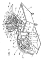
- Figure 1 is a perspective view of an excavating apparatus according to the invention and
- Figure 2 is a partially sectioned side elevational view thereof.
- With reference to the drawings, the apparatus comprises a
rugged pedestal 10 which carries an elongatehorizontal sleeve 12 at its upper end. - A
strong shaft 14 is rotatably mounted in bearings, not .shown, in thesleeve 12 and its horizontal axis is indicated A in Figure 2. - At one end of the sleeve 12 (the left-hand end in the drawings), the
pedestal 10 supports, on abracket 16, a geared motor unit the reduction gear of which, indicated 18, is of the worm screw type and the motor of which, of the pneumatic type, is indicated 20. The output shaft of thereduction gear 18 is connected through aflexible coupling 22 to the corresponding end of theshaft 14. - At the opposite end (to the right in the drawings) the
shaft 14 carries astrong attachment flange 24 the general plane of which is at an angle d to the horizontal axis of rotation A for the purposes which will be clarified below. - The
shaft 14 with itsflange 24 constitutes a rotary assembly for rotating a fixture generally indicated 26 about the horizontal axis A. - The
fixture 26 comprises abase plate 28 having anattachment flange 30 at one end (to the left in the drawings). The general planes of theplate 28 and of theflange 30 are perpendicular to each other. - The
attachment flange 30 is bolted to theattachment flange 24 of theshaft 14. - The structure of the
base plate 28 and of theattachment flange 30 is reinforced by lateralwelded fillets - On that face of the
base plate 28 which in the condition of Figure 2 faces upwardly there areresilient supports 36 on which is mounted aplatform 38. -
Lateral pillars 40 are upstanding from theplatform 38 and carry respective pneumaticvibratory hammers 42 thestriker members 44 whereof are directed towards the space between thepillars 40. - On the
platform 38 are mountedresilient pads 46 for supporting a casting to be decored, generally indicated C and shown in broken outline in Figure 2. In the specific case, the casting is a light alloy cylinder head of an internal combustion engine. - Two further pillars upstand from the
platform 38, one of which located nearer theflange 30 is indicated 48. The other pillar, located at the opposite end of the platform 38 (to the right in the drawings), is indicated 50. - The
pillar 48 carries two upper-pads 52 which are adjustable in height and thepillar 50 carries atoggle clamp 54, also with anadjustable pad 56. - The
platform 38 also carries lateralfixed pads 58 and thepillar 48 carriesend pads 60. - The casting C to be decored is mounted on the
fixture 26 disposed as in Figure 2, the casting C being inserted in the direction of the arrow D onto the bearing .pads 46 and between thelateral pads 58 until it is brought against theend pads 60. Under these conditions the more forward part of the casting C is clamped under theupper pads 52 and theclamp 54 is then closed so as to grip and position the casting C on thefixture 26. - Under these conditions the risers of the casting C are located in correspondence with the
strikers 44 of thepneumatic hammers 42. - The arrangement of the positioning and support means for the casting, constituted by the various pads as well as that of the retaining means constituted by the
clamp 54 is not limitative since this will be chosen according to the shape of the casting to be clamped. Thus the disposition of the pneumatic hammers is also not limitative. - The tool is also provided with blower means in the form of
nozzles 62 directed towards the casting C and carried by manifold tubes (not shown). - Two
compressed air tubes sleeve 12 and communicate with corresponding annularperipheral grooves shaft 14 to constitute rotary joints. Thegrooves longitudinal ducts shaft 14. These ducts extend through theattachment flange 24 and communicate sealingly with respective ports (not shown) formed in theattachment flange 30. These ports have- connectors from which extend respective tubes for supplying thepneumatic hammers 42 and thenozzles 62 respectively. - In order to decore the casting C after it has been installed in a manner illustrated in Figure 2, the
pneumatic hammers 42 and thenozzles 62 are supplied and thefixture 26 is rotated by the pneumatic motor 20. - The casting C, at its right. and left-hand ends in Figure 2, has respective apertures E which communicate with its internal cavities. The arrangement of the
fixture 26 is such that the axis F of alignment of the two apertures E intercepts the axis A at an angle other than zero. Preferably the angle β is also other than 90°. Thus the rotation of thefixture 26 about the axis A causes a precessing movement of the axis F, which describes a cone the half angle of which at the vertix is β. - As will be understood, when the
fixture 26 is in the position indicated in continuous outline in Figure 2, the left hand aperture E is lower than the right hand aperture and vice versa when thefixture 26 is rotated through 180°, as illustrated in broken outline in the same Figure 2. - .Thus, during vibration and blowing, the clay within the inner cavities of the casting C is discharged alternately from one aperture E and the other, being collected in a removable skip 76 (Figure 1) which is located under the
fixture 26. - The angle p and hence the angle α, which is complementary thereto, is chosen experimentally so as to achieve optimum discharge of the clay from the end apertures of the casting. In a specific case in which the casting is a light alloy cylinder head, the angle β may conveniently be 30°.
- Further to ensure optimum discharge conditions of the clay from the end apertures of the casting, the speed of rotation about the axis A, the number of rotations and the rotation time will be determined experimentally.
- The operation of the apparatus may be made completely automatic and to advantage the rotation is stopped by a timer.
- In order to ensure that the
fixture 26 stops in the position illustrated in continuous line in Figure 2, thereduction gear 18 carries awheel 78 on a second output shaft, acam 80 being fixed in an angularly adjustable position to this wheel. The cam cooperates at each revolution of thewheel 78 with aswitch 82. The control circuit is such that operation of theswitch 82, which occurs at each passage of thecam 80, has no effect until the start of the final revolution in which the timer brings theswitch 82 into the control circuit and on passage of thecam 80 causes the stoppage of thepneumatic motor 20 and stops the pneumatic supply to the hammers'42 and to thenozzles 62. - The position of the
tool 26 relative to theshaft 14, in which the "upper" face of theplatform 38 faces upwardly and has a slope descending towards theshaft 14 is convenient both for loading and unloading the cast ing C, these being carried out by an operator or by a transfer system placed "frontally" (to the right in Figure 2).
Claims (10)
1. Decoring apparatus for hollow metal castings of elongate form with end aperture, of the type comprising a fixture (26) provided with positioning, support and retaining means (46,52,54,56,58,60) for the casting (C) to be decored, means (42) for vibrating the casting and blower means (62), the fixture being arranged to support the casting in a position in which one of the end apertures (E) is located at a lower level than the other in order to facilitate the discharge of core clay through the said aperture, characterised in that the fixture (26) is supported by an assembly (14, 24) which is rotatable about a horizontal axis (A) and is so arranged that, with the casting (C) held by the fixture (26) the axis (F) of alignment of its two end apertures (E) is at an angle (p) other than zero to the horizontal axis (A) of rotation of the assembly (12,24).
2. Decoring apparatus according to Claim 1, characterised in that the fixture (26) is so arranged that, with the casting (C) held by the fixture, the said axis of alignment (F) is at an angle (p) other than zero and other than 90° to the said horizontal axis (A) so that this axis of alignment (F) effects a precessing movement about the horizontal axis (A).
3. Decoring apparatus according to Claim 1 or Claim 2, characterised in that it includes a pedestal (10) on which a horizontal driven shaft (14) is rotatably mounted and at one end of which the fixture (26) is secured.
4. Decoring apparatus according to Claim 3, characterised in that the fixture (26) includes a base plate (28) on which is mounted, by resilient support means (36), a platform (38) which in its turn carries the positioning means (46, 56, 58, 60), the support means (58), the retaining means (52, 54), the hammer means (42) and the blower means (62), the shaft (14) has an end attachment flange (24) and the base plate (28) has a corresponding attachment flange (30), the flanges (24, 30) lying in a general plane which is at an angle (α) to the axis of rotation (A) which is complementary to that formed by the said axis of alignment (F) with the said axis (A).
5. Decoring apparatus according to Claim 4, characterised in that the flange (30) of the base plate (28) of the tool (26) lies in a plane which is generally perpendicular to that of the plate (28), "and the flange (24) of the shaft (14) is at the said complementary angle (d) to the axis of rotation (A).
6. Decoring apparatus according to Claim 4, characterised in that the positioning, support and retaining means are located on a face of the platform (38) which, when facing upwardly, has a slope which descends towards the shaft (14).
7. Decoring apparatus according to any one of Claims 4 to 6, characterised in that longitudinal ducts (72,74) are formed in the shaft (14) and terminate at one end at respective rotary joints (68, 70) connected to respective compressed air sources and at the other end open into the attachment flange (24) of the shaft (14) and sealingly communicate with respective ports in the attachment flange (30) of the platform (28), these ports being connected by respective tubes to the vibratory means (42) and the blower means (62).
8. Decoring apparatus according to any one of Claims 4 to 7, characterised in that at the end of the shaft (14) opposite its attachment flange (24) the pedestal (10) carries a geared motor (18, 20) to which this opposite end is connected by means of a coupling (22).
9. Decoring apparatus according to Claim 8, characterised.in that the coupling (22) is-a flexible coupling.
10. Decoring apparatus according to Claim 8, characterised in that the geared motor (18, 20) is of the pneumatic type.
Applications Claiming Priority (2)
| Application Number | Priority Date | Filing Date | Title |
|---|---|---|---|
| IT68464/82A IT1157143B (en) | 1982-12-14 | 1982-12-14 | GROUNDING DEVICE FOR CABLE METAL JETS |
| IT6846482 | 1982-12-14 |
Publications (1)
| Publication Number | Publication Date |
|---|---|
| EP0111461A1 true EP0111461A1 (en) | 1984-06-20 |
Family
ID=11309487
Family Applications (1)
| Application Number | Title | Priority Date | Filing Date |
|---|---|---|---|
| EP83830254A Withdrawn EP0111461A1 (en) | 1982-12-14 | 1983-12-07 | Decoring apparatus for hollow metal castings |
Country Status (3)
| Country | Link |
|---|---|
| EP (1) | EP0111461A1 (en) |
| BR (1) | BR8306978A (en) |
| IT (1) | IT1157143B (en) |
Cited By (12)
| Publication number | Priority date | Publication date | Assignee | Title |
|---|---|---|---|---|
| JPH01241372A (en) * | 1988-03-23 | 1989-09-26 | Osaka Shell Kogyosho:Kk | Method and apparatus for discharging core raw material for casting |
| US5460219A (en) * | 1991-02-07 | 1995-10-24 | Massin Limited Company | Method and devices for decoring castings |
| WO2000054910A1 (en) * | 1999-03-17 | 2000-09-21 | Cestaro Fonderie S.R.L. | Device for decoring casting pieces |
| EP1040884A1 (en) * | 1999-04-02 | 2000-10-04 | Fata Aluminium Division of Fata Group S.p.A. | Vibratory decoring machine |
| FR2800999A1 (en) * | 1999-11-12 | 2001-05-18 | Osborm Emi | Device for the mechanical removal of cores from hollow foundry pieces, such as cylinder heads, engine blocks, inlet collectors and suspension arms for motor cars and similar applications |
| GB2385549A (en) * | 1999-04-17 | 2003-08-27 | Yoshitaka Aoyama | Casting sand shake-out apparatus |
| GB2348839B (en) * | 1999-04-17 | 2003-10-08 | Yoshitaka Aoyama | Casting sand shake-out method and its apparatus |
| EP1995002A3 (en) * | 2007-05-08 | 2010-01-27 | August Moessner GmbH & Co. KG. | Shaking device and method for removing core sand from hollow moulds |
| WO2014158098A1 (en) | 2013-03-29 | 2014-10-02 | Rc Simit D.O.O. | Boring of sand cores from castings |
| WO2020163886A1 (en) * | 2019-02-11 | 2020-08-20 | Fill Gesellschaft M.B.H. | Decoring hammer for decoring castings and decoring machine and method for decoring a casting |
| WO2020234818A1 (en) * | 2019-05-22 | 2020-11-26 | O.M.Ler S.R.L. | De-coring machine for foundry castings with rotating housing for foundry castings and related method for de-coring foundry castings |
| WO2020234820A1 (en) * | 2019-05-22 | 2020-11-26 | O.M.Ler S.R.L. | De-coring machine for de-coring a plurality of foundry castings and method for de-coring |
Citations (2)
| Publication number | Priority date | Publication date | Assignee | Title |
|---|---|---|---|---|
| GB262851A (en) * | 1925-09-14 | 1926-12-14 | John Taylor Stoney | Improvements in and relating to the method of and apparatus for cleaning articles such as castings |
| DE3010964A1 (en) * | 1979-04-04 | 1980-11-06 | Fischer Ag Georg | METHOD AND DEVICE FOR EMPTYING WORKPIECES HAVING CAVITIES |
-
1982
- 1982-12-14 IT IT68464/82A patent/IT1157143B/en active
-
1983
- 1983-12-07 EP EP83830254A patent/EP0111461A1/en not_active Withdrawn
- 1983-12-14 BR BR8306978A patent/BR8306978A/en unknown
Patent Citations (2)
| Publication number | Priority date | Publication date | Assignee | Title |
|---|---|---|---|---|
| GB262851A (en) * | 1925-09-14 | 1926-12-14 | John Taylor Stoney | Improvements in and relating to the method of and apparatus for cleaning articles such as castings |
| DE3010964A1 (en) * | 1979-04-04 | 1980-11-06 | Fischer Ag Georg | METHOD AND DEVICE FOR EMPTYING WORKPIECES HAVING CAVITIES |
Cited By (12)
| Publication number | Priority date | Publication date | Assignee | Title |
|---|---|---|---|---|
| JPH01241372A (en) * | 1988-03-23 | 1989-09-26 | Osaka Shell Kogyosho:Kk | Method and apparatus for discharging core raw material for casting |
| US5460219A (en) * | 1991-02-07 | 1995-10-24 | Massin Limited Company | Method and devices for decoring castings |
| WO2000054910A1 (en) * | 1999-03-17 | 2000-09-21 | Cestaro Fonderie S.R.L. | Device for decoring casting pieces |
| EP1040884A1 (en) * | 1999-04-02 | 2000-10-04 | Fata Aluminium Division of Fata Group S.p.A. | Vibratory decoring machine |
| GB2385549A (en) * | 1999-04-17 | 2003-08-27 | Yoshitaka Aoyama | Casting sand shake-out apparatus |
| GB2348839B (en) * | 1999-04-17 | 2003-10-08 | Yoshitaka Aoyama | Casting sand shake-out method and its apparatus |
| FR2800999A1 (en) * | 1999-11-12 | 2001-05-18 | Osborm Emi | Device for the mechanical removal of cores from hollow foundry pieces, such as cylinder heads, engine blocks, inlet collectors and suspension arms for motor cars and similar applications |
| EP1995002A3 (en) * | 2007-05-08 | 2010-01-27 | August Moessner GmbH & Co. KG. | Shaking device and method for removing core sand from hollow moulds |
| WO2014158098A1 (en) | 2013-03-29 | 2014-10-02 | Rc Simit D.O.O. | Boring of sand cores from castings |
| WO2020163886A1 (en) * | 2019-02-11 | 2020-08-20 | Fill Gesellschaft M.B.H. | Decoring hammer for decoring castings and decoring machine and method for decoring a casting |
| WO2020234818A1 (en) * | 2019-05-22 | 2020-11-26 | O.M.Ler S.R.L. | De-coring machine for foundry castings with rotating housing for foundry castings and related method for de-coring foundry castings |
| WO2020234820A1 (en) * | 2019-05-22 | 2020-11-26 | O.M.Ler S.R.L. | De-coring machine for de-coring a plurality of foundry castings and method for de-coring |
Also Published As
| Publication number | Publication date |
|---|---|
| BR8306978A (en) | 1984-07-24 |
| IT1157143B (en) | 1987-02-11 |
| IT8268464A0 (en) | 1982-12-14 |
Similar Documents
| Publication | Publication Date | Title |
|---|---|---|
| EP0111461A1 (en) | Decoring apparatus for hollow metal castings | |
| US4643243A (en) | Machine for impact cleaning casting | |
| US4511125A (en) | Ladle scraper mechanism | |
| US5071487A (en) | Method and apparatus for cleaning passageways in metal castings | |
| US4256167A (en) | Apparatus for centrifugal casting | |
| DE58900385D1 (en) | DEVICE FOR COREING CASTING PIECES. | |
| US5054155A (en) | Apparatus for cleaning passageways in metal castings | |
| JP3004170B2 (en) | Cleaning device for hollow part of cast camshaft | |
| JP3386148B2 (en) | Casting equipment | |
| US3648762A (en) | Centrifugal casting machine | |
| JPH0647524A (en) | Device for taking out casting core | |
| US4625465A (en) | Hone stop assembly | |
| SU1560381A1 (en) | Unit for surfacing internal cylindrical surfaces of parts by centrifugal casting | |
| SU874228A1 (en) | Device for cleaning articles by vibration | |
| CN215038647U (en) | A prefabricated component spraying device on both sides of the front and back | |
| CN222095784U (en) | High-precision engine crankshaft casting manufacturing device | |
| CN115262355B (en) | Crack pouring machine | |
| US4428414A (en) | Apparatus for cleaning faced metal moulds of used facing | |
| CN219787991U (en) | Surface sand blasting equipment for automatic feeding and discharging of dental implant | |
| JPH06277977A (en) | Chip removing device | |
| JPH07241665A (en) | Slab deburring device | |
| JPH0112952Y2 (en) | ||
| CN215357976U (en) | Shot blasting machine for cleaning brake disc | |
| JPS619961A (en) | Casting product core ejection method | |
| JPH0527247Y2 (en) |
Legal Events
| Date | Code | Title | Description |
|---|---|---|---|
| PUAI | Public reference made under article 153(3) epc to a published international application that has entered the european phase |
Free format text: ORIGINAL CODE: 0009012 |
|
| AK | Designated contracting states |
Designated state(s): AT BE CH DE FR GB LI LU NL SE |
|
| 17P | Request for examination filed |
Effective date: 19841214 |
|
| R17P | Request for examination filed (corrected) |
Effective date: 19841214 |
|
| STAA | Information on the status of an ep patent application or granted ep patent |
Free format text: STATUS: THE APPLICATION IS DEEMED TO BE WITHDRAWN |
|
| 18D | Application deemed to be withdrawn |
Effective date: 19860701 |
|
| RIN1 | Information on inventor provided before grant (corrected) |
Inventor name: GADDI, ROBERTO |