EP0111353B1 - Blanket-medium/brine interface detection in a solution-mining process - Google Patents
Blanket-medium/brine interface detection in a solution-mining process Download PDFInfo
- Publication number
- EP0111353B1 EP0111353B1 EP83201618A EP83201618A EP0111353B1 EP 0111353 B1 EP0111353 B1 EP 0111353B1 EP 83201618 A EP83201618 A EP 83201618A EP 83201618 A EP83201618 A EP 83201618A EP 0111353 B1 EP0111353 B1 EP 0111353B1
- Authority
- EP
- European Patent Office
- Prior art keywords
- medium
- tool
- blanket
- electrode means
- brine
- Prior art date
- Legal status (The legal status is an assumption and is not a legal conclusion. Google has not performed a legal analysis and makes no representation as to the accuracy of the status listed.)
- Expired
Links
Images


Classifications
-
- G—PHYSICS
- G01—MEASURING; TESTING
- G01F—MEASURING VOLUME, VOLUME FLOW, MASS FLOW OR LIQUID LEVEL; METERING BY VOLUME
- G01F23/00—Indicating or measuring liquid level or level of fluent solid material, e.g. indicating in terms of volume or indicating by means of an alarm
- G01F23/22—Indicating or measuring liquid level or level of fluent solid material, e.g. indicating in terms of volume or indicating by means of an alarm by measuring physical variables, other than linear dimensions, pressure or weight, dependent on the level to be measured, e.g. by difference of heat transfer of steam or water
- G01F23/26—Indicating or measuring liquid level or level of fluent solid material, e.g. indicating in terms of volume or indicating by means of an alarm by measuring physical variables, other than linear dimensions, pressure or weight, dependent on the level to be measured, e.g. by difference of heat transfer of steam or water by measuring variations of capacity or inductance of capacitors or inductors arising from the presence of liquid or fluent solid material in the electric or electromagnetic fields
- G01F23/263—Indicating or measuring liquid level or level of fluent solid material, e.g. indicating in terms of volume or indicating by means of an alarm by measuring physical variables, other than linear dimensions, pressure or weight, dependent on the level to be measured, e.g. by difference of heat transfer of steam or water by measuring variations of capacity or inductance of capacitors or inductors arising from the presence of liquid or fluent solid material in the electric or electromagnetic fields by measuring variations in capacitance of capacitors
-
- E—FIXED CONSTRUCTIONS
- E21—EARTH DRILLING; MINING
- E21B—EARTH DRILLING, e.g. DEEP DRILLING; OBTAINING OIL, GAS, WATER, SOLUBLE OR MELTABLE MATERIALS OR A SLURRY OF MINERALS FROM WELLS
- E21B43/00—Methods or apparatus for obtaining oil, gas, water, soluble or meltable materials or a slurry of minerals from wells
- E21B43/28—Dissolving minerals other than hydrocarbons, e.g. by an alkaline or acid leaching agent
-
- E—FIXED CONSTRUCTIONS
- E21—EARTH DRILLING; MINING
- E21B—EARTH DRILLING, e.g. DEEP DRILLING; OBTAINING OIL, GAS, WATER, SOLUBLE OR MELTABLE MATERIALS OR A SLURRY OF MINERALS FROM WELLS
- E21B47/00—Survey of boreholes or wells
- E21B47/04—Measuring depth or liquid level
- E21B47/047—Liquid level
Definitions
- the invention relates to a downhole tool for detecting capacitively the position or level of a blanket-medium/brine interface in subterranean salt cavities wherein the salt layers are mined by pumping a solution medium into the layers and by pumping out saturated brine, and wherein the blanket medium protects the roof of the subterranean cavity, wherein said tool is provided with a first electrode means which is placed at a determined distance from a second electrode means, both said electrode means being adapted for capacitive measurement and further comprising means for determining the capacitance of the said first and second electrode means, the said tool further being provided with means adapted to transmit the obtained information up-hole.
- Such a tool is known from DE-A-2,621,142.
- subterranean salt layers which are situated at a relatively large depth, for example 1500-2000 metres, are mined by injecting a suitable medium such as fresh water into the layers and pumping out saturated brine through separate tubings.
- the salt layers have for example a thickness of about 100 metres.
- the saturated brine is processed further in any way suitable for the purpose in order to obtain the desired products.
- the fresh water injection point is above the brine off-take point.
- reverse flow is also possible. It will be clear that, when fresh water is injected into the salt layers, a subterranean structure having a determined shape and comprising brine will be developed in these salt layers.
- a "blanket medium” is oil, but it will be clear to those skilled in the art that any suitable medium, for example gas, can be used to protect the roof of the structure.
- the tool of the invention therefore is characterized by that the first electrode means consists of a plurality of individual segments arranged one above another, wherein each individual segment has a height between 5 and 50 cm and a width between 1 and 5 cm, and in that the said second electrode means is the wall of a tubing, on which the tool is installed.
- US-A-2,688,872 discloses a downhole tool for the identification of well fluids and for determining the rate of oil and gas production, wherein a series of electrodes is present in order to measure the resistance of the surrounding media.
- GB-A-578,886 discloses a capacitive segmented level indicator for liquids in a storage cavern or vessel.
- the specific tool of the invention in order to measure accurately the blanket medium/brine interface in solution mining cannot be derived therefrom.
- Another advantage of the downhole tool of the invention is that it allows calibration of the level measuring system during the actual measurement by observing the capacitance of segments fully immersed in the brine and oil.
- a further advantage of the tool of the invention is that it allows compensation of homogeneous fouling of the measuring section.
- the downhole tool of the invention has been based upon the capacitive measuring principle, in which the difference in capacitances for blanket medium and for cavity medium (brine) is used in order to determine the interface position.
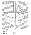
- a borehole 1 has been shown together with an injection tubing 2 and a production tubing 3.
- the reference numbers 2a-d represent successive positions of the injection tubing 2.
- a suitable medium such as fresh water
- brine 4 is developed in this layer and is pumped out through the production tubing 3 in any suitable way.
- the roof of the structure is protected by a blanket medium, such as oil.
- a blanket medium such as oil.
- the oil level is moved upwards over, for example, 2 metres by producing back the oil to make a new "cut”.
- the injection point is taken upwards by the same distance. In this way successive "morning glory" structures B', C', D' can be developed.
- Fig. 1 the roof of the upper structure D' is protected by the oil 5', which is injected through the borehole 1 in any way suitable for the purpose and provides a protective oil layer 5.
- Fig. 2 shows schematically a cavern 6 in the salt layer A, in which a change in blanket-medium/ brine interface level has occurred due to local roof failure.
- a "chimney” 7 has developed and comprises oil 5", so that part of the roof 8 is unprotected.
- the reference numbers 1, 2, 3, 4 and 5' are the same as used in Fig. 1.
- Fig. 3a shows schematically an advantageous embodiment of the downhole tool of the invention; in this embodiment of the tool both the first means and the second means of measuring section of the tool comprise a plurality of individual segments, thus forming capacitors 1', 1 "-13', 13", which are situated one above another. Each individual segment has a height between 5 and 50 cm and a width 1 and 5 cm.
- the downhole tool can be installed in any way suitable for the purpose.
- the individual capacitors 1', 1 "-13', 13" are connected in any way suitable for the purpose to any suitable downhole electronics, schematically shown as block 14, in order to measure the capacitances between the segments of a capacitor.
- the downhole electronics may, for example, consist of oscillators and a multiplexer (not shown). Such components and the operation thereof are known as such to those skilled in the art and will not be described in detail.
- the block 14 is connected in any way suitable for the purpose to the earth surface 15 (not shown) in order to transmit the measured capacitances to suitable devices for processing further the obtained data (not shown for reasons of clarity).
- a temperature sensor 17 and/or a pressure sensor 16 may be provided at any suitable position on the downhole tool in order to obtain information concerning the temperature and pressure in the cavern.
- Geothermal temperatures at the cavern depth are about 60°C.
- the temperature of the injection fluids can vary between 10°C and 60°C. Practice has so far shown that the cavern temperature during production remains at about 60°C, even when water of 10°C is injected. However, injection of hot water up to 120°C may be considered. Thus, it will be clear that any downhole electronics should be able to operate at temperatures up to 120°C.
- the operating pressure in the cavern is up to some 500 bar.
- Fig. 3b represents schematically another advantageous embodiment of the downhole tool of the invention; in this embodiment of the tool the first means consists of individual segments 1 'a, 2'a ... 13'a, which are placed one below another. In this embodiment the segments are overlapping.
- the second means consisting of an electrode Z (schematically shown). The said first means and the said second means are connected by any means suitable for the purpose to a block 14a.
- the block 14a has the same function as in Fig. 3a, and has been connected to the earth surface by any means suitable for the purpose (schematically shown as 15a). Further a pressure sensor 16a and a temperature sensor 17a have been represented.
- Fig. 4 shows a longitudinal section of another advantageous embodiment of the invention.
- the downhole tool of the invention is installed on an injection tubing 18".
- the way of installing such an injection tubing inside a borehole is known to those skilled in the art and will not be described in detail.
- the downhole tool 18 is provided with a measuring section 18'.
- the measuring section 18' may, for example, have a length of about 2 metres. However, it will be appreciated that any length suitable for the purpose is possible.
- the reference number 9 represents the flow path of the injected water through the injection tubing 18".
- the injection tubing is provided with a recessed part 20, made for example of stainless steel.
- the measuring section 18' is provided with a plurality of segments 21', arranged one above another, for example in an overlapping range.
- the diameter D of the tubing is for example 6.5 cm. However, it will be appreciated that any tubing diameter suitable for the purpose can be used.
- the said segments have, for example, a height of 20 cm and a width of 2 cm.
- the number of the segments is 13 in an advantageous embodiment, but any suitable number can be applied.
- suitable downhole electronics have been installed in the measuring section 18' (not shown in detail for reasons of clarity).
- the down- hole electronics and segments are built into a suitable medium 22, for example an epoxy-glass reinforced module.
- the tubing 20 may be provided with a protecting end section 23.
- the mechanical connections of the end section and the injection tubing will be clear to those skilled in the art and will not be described in detail.
- a retaining block 24 may be present at a first side of the module 22 in order to retain the said module.
- the retaining block 24 may for example be bolted onto the tubing 20.
- a support 25 may be present at the other side of the module 22 and is adapted to attach a cable 26 to the measuring section 18'.
- a suitable cable feedthrough 27 from the measuring section 18' to the module 22 is present.
- the whole system can be run on a cable, for example a mono-conductor cable 26, which remains connected during operation to provide the electrical communication to the surface.
- the segments 21' may have any shape suitable for the purpose and are not necessarily flat. Curved segments are for example possible in order to match the circular shape of the tubing.
Landscapes
- Physics & Mathematics (AREA)
- Engineering & Computer Science (AREA)
- Geology (AREA)
- Life Sciences & Earth Sciences (AREA)
- Mining & Mineral Resources (AREA)
- Fluid Mechanics (AREA)
- General Life Sciences & Earth Sciences (AREA)
- Environmental & Geological Engineering (AREA)
- Geochemistry & Mineralogy (AREA)
- Power Engineering (AREA)
- Geophysics (AREA)
- Electromagnetism (AREA)
- Thermal Sciences (AREA)
- General Physics & Mathematics (AREA)
- Geophysics And Detection Of Objects (AREA)
- Measurement Of Levels Of Liquids Or Fluent Solid Materials (AREA)
Description
- The invention relates to a downhole tool for detecting capacitively the position or level of a blanket-medium/brine interface in subterranean salt cavities wherein the salt layers are mined by pumping a solution medium into the layers and by pumping out saturated brine, and wherein the blanket medium protects the roof of the subterranean cavity, wherein said tool is provided with a first electrode means which is placed at a determined distance from a second electrode means, both said electrode means being adapted for capacitive measurement and further comprising means for determining the capacitance of the said first and second electrode means, the said tool further being provided with means adapted to transmit the obtained information up-hole.
- Such a tool is known from DE-A-2,621,142.
- In a solution-mining process subterranean salt layers which are situated at a relatively large depth, for example 1500-2000 metres, are mined by injecting a suitable medium such as fresh water into the layers and pumping out saturated brine through separate tubings. The salt layers have for example a thickness of about 100 metres.
- The saturated brine is processed further in any way suitable for the purpose in order to obtain the desired products. Usually the fresh water injection point is above the brine off-take point. However, reverse flow is also possible. It will be clear that, when fresh water is injected into the salt layers, a subterranean structure having a determined shape and comprising brine will be developed in these salt layers.
- It is now desirable to protect the roof of such a structure by a "blanket medium" to prevent uncontrolled dissolution. An example of such a "blanket medium" is oil, but it will be clear to those skilled in the art that any suitable medium, for example gas, can be used to protect the roof of the structure.
- Further, as the radial extent of the mined section increases, the roof-surface area becomes larger, so that additional oil must be injected to maintain a sufficiently thick protecting layer between roof and brine.
- This can be achieved by keeping the oil-brine interface at a fixed level. Insufficient thickness of the blanket will result in local exposure of the roof to the brine, which in turn will cause more oil to disappear. Another cause of movement of the oil-brine interface could be local roof failure. Part of the roof may collapse, creating a "chimney", into which the oil can disappear leaving the remaining part of the roof unprotected. Hence, a safe mining process requires a continuous monitoring of the interface position and it will be clear that it is very important to have a good indication of the said position.
- However, the accuracy of the tool of DE-A-2,621,142 is susceptible of improvement.
- It is therefore an object of the invention to provide a down-hole tool to be used in a solution-mining process, which can detect accurately the interface position between oil-brine.
- It is another object of the invention to provide a downhole tool to be used in a solution mining process which can be used to estimate the roof area at various stages of the mining process by measuring the change of the interface level when a known volume of oil is injected.
- The tool of the invention therefore is characterized by that the first electrode means consists of a plurality of individual segments arranged one above another, wherein each individual segment has a height between 5 and 50 cm and a width between 1 and 5 cm, and in that the said second electrode means is the wall of a tubing, on which the tool is installed.
- In this way it is possible to measure the interface position with an accuracy better than ±1 cm.
- It can be remarked that US-A-2,688,872 discloses a downhole tool for the identification of well fluids and for determining the rate of oil and gas production, wherein a series of electrodes is present in order to measure the resistance of the surrounding media.
- Further, GB-A-578,886 discloses a capacitive segmented level indicator for liquids in a storage cavern or vessel. However, the specific tool of the invention in order to measure accurately the blanket medium/brine interface in solution mining cannot be derived therefrom.
- Another advantage of the downhole tool of the invention is that it allows calibration of the level measuring system during the actual measurement by observing the capacitance of segments fully immersed in the brine and oil.
- A further advantage of the tool of the invention is that it allows compensation of homogeneous fouling of the measuring section.
- The downhole tool of the invention will now be described by way of example in more detail with reference to the accompanying drawings, in which:
- Fig. 1 represents schematically a development of successive subterranean structures, obtained by a solution-mining process;
- Fig. 2 represents schematically a subterranean structure, in which the blanket-medium/brine interface level has changed due to local roof failure;
- Fig. 3a and Fig. 3b represent schematically advantageous embodiments of the invention;
- Fig. 4 shows a longitudinal cross-section of an advantageous embodiment of the invention.
- The downhole tool of the invention has been based upon the capacitive measuring principle, in which the difference in capacitances for blanket medium and for cavity medium (brine) is used in order to determine the interface position.
- The capacitive measuring principle as such is known to those skilled in the art and will not be described in detail.
- With reference now to Fig. 1, a borehole 1 has been shown together with an injection tubing 2 and a production tubing 3. The reference numbers 2a-d represent successive positions of the injection tubing 2.
- In the first position 2a of the injection tubing 2 a suitable medium, such as fresh water, is injected into the salt layer A; brine 4 is developed in this layer and is pumped out through the production tubing 3 in any suitable way.
- When, as shown, the fresh water is injected above the off-take point, a so-called "morning glory" structure A' results.
- As already indicated in the above, the roof of the structure is protected by a blanket medium, such as oil. After the "morning glory" structure A' has reached a determined diameter, for example about 100 metres, the oil level is moved upwards over, for example, 2 metres by producing back the oil to make a new "cut". At the same time the injection point is taken upwards by the same distance. In this way successive "morning glory" structures B', C', D' can be developed.
- In Fig. 1 the roof of the upper structure D' is protected by the oil 5', which is injected through the borehole 1 in any way suitable for the purpose and provides a
protective oil layer 5. - Fig. 2 shows schematically a cavern 6 in the salt layer A, in which a change in blanket-medium/ brine interface level has occurred due to local roof failure. A "chimney" 7 has developed and comprises
oil 5", so that part of theroof 8 is unprotected. The reference numbers 1, 2, 3, 4 and 5' are the same as used in Fig. 1. - Fig. 3a shows schematically an advantageous embodiment of the downhole tool of the invention; in this embodiment of the tool both the first means and the second means of measuring section of the tool comprise a plurality of individual segments, thus forming capacitors 1', 1 "-13', 13", which are situated one above another. Each individual segment has a height between 5 and 50 cm and a
width 1 and 5 cm. As will be explained afterwards, in particular with reference to Fig. 4, the downhole tool can be installed in any way suitable for the purpose. The individual capacitors 1', 1 "-13', 13", are connected in any way suitable for the purpose to any suitable downhole electronics, schematically shown asblock 14, in order to measure the capacitances between the segments of a capacitor. - The downhole electronics may, for example, consist of oscillators and a multiplexer (not shown). Such components and the operation thereof are known as such to those skilled in the art and will not be described in detail.
- The
block 14 is connected in any way suitable for the purpose to the earth surface 15 (not shown) in order to transmit the measured capacitances to suitable devices for processing further the obtained data (not shown for reasons of clarity). - In an advantageous embodiment of the invention a
temperature sensor 17 and/or apressure sensor 16 may be provided at any suitable position on the downhole tool in order to obtain information concerning the temperature and pressure in the cavern. Geothermal temperatures at the cavern depth are about 60°C. The temperature of the injection fluids can vary between 10°C and 60°C. Practice has so far shown that the cavern temperature during production remains at about 60°C, even when water of 10°C is injected. However, injection of hot water up to 120°C may be considered. Thus, it will be clear that any downhole electronics should be able to operate at temperatures up to 120°C. The operating pressure in the cavern is up to some 500 bar. - Fig. 3b represents schematically another advantageous embodiment of the downhole tool of the invention; in this embodiment of the tool the first means consists of individual segments 1 'a, 2'a ... 13'a, which are placed one below another. In this embodiment the segments are overlapping. The second means consisting of an electrode Z (schematically shown). The said first means and the said second means are connected by any means suitable for the purpose to a block 14a.
- The block 14a has the same function as in Fig. 3a, and has been connected to the earth surface by any means suitable for the purpose (schematically shown as 15a). Further a
pressure sensor 16a and atemperature sensor 17a have been represented. - Fig. 4 shows a longitudinal section of another advantageous embodiment of the invention. In this embodiment the downhole tool of the invention is installed on an
injection tubing 18". The way of installing such an injection tubing inside a borehole is known to those skilled in the art and will not be described in detail. Thedownhole tool 18 is provided with a measuring section 18'. The measuring section 18' may, for example, have a length of about 2 metres. However, it will be appreciated that any length suitable for the purpose is possible. In this embodiment the reference number 9 represents the flow path of the injected water through theinjection tubing 18". - The injection tubing is provided with a recessed
part 20, made for example of stainless steel. The measuring section 18' is provided with a plurality of segments 21', arranged one above another, for example in an overlapping range. The diameter D of the tubing is for example 6.5 cm. However, it will be appreciated that any tubing diameter suitable for the purpose can be used. - The said segments have, for example, a height of 20 cm and a width of 2 cm. The number of the segments is 13 in an advantageous embodiment, but any suitable number can be applied.
- Further, suitable downhole electronics have been installed in the measuring section 18' (not shown in detail for reasons of clarity). The down- hole electronics and segments are built into a
suitable medium 22, for example an epoxy-glass reinforced module. - The
tubing 20 may be provided with a protectingend section 23. The mechanical connections of the end section and the injection tubing will be clear to those skilled in the art and will not be described in detail. - Further, a retaining
block 24 may be present at a first side of themodule 22 in order to retain the said module. The retainingblock 24 may for example be bolted onto thetubing 20. Asupport 25 may be present at the other side of themodule 22 and is adapted to attach acable 26 to the measuring section 18'. - A
suitable cable feedthrough 27 from the measuring section 18' to themodule 22 is present. The whole system can be run on a cable, for example a mono-conductor cable 26, which remains connected during operation to provide the electrical communication to the surface. - In the embodiment of Fig. 4 the capacitance between the segments and the tubing wall is measured.
- It will be appreciated that the segments 21' may have any shape suitable for the purpose and are not necessarily flat. Curved segments are for example possible in order to match the circular shape of the tubing.
- It will be clear that the downhole tool has to operate in a hostile environment (saline water, high pressure, elevated temperatures, etc.).
- Thus, any suitable material above to satisfy such requirements should be used. Various modifications of the invention will become apparent to those skilled in the art from the foregoing description and accompanying drawings. Such modification are intended to fall within the scope of the appended claims.
Claims (2)
Applications Claiming Priority (2)
| Application Number | Priority Date | Filing Date | Title |
|---|---|---|---|
| GB8235500 | 1982-12-13 | ||
| GB8235500 | 1982-12-13 |
Publications (3)
| Publication Number | Publication Date |
|---|---|
| EP0111353A2 EP0111353A2 (en) | 1984-06-20 |
| EP0111353A3 EP0111353A3 (en) | 1985-12-11 |
| EP0111353B1 true EP0111353B1 (en) | 1988-04-13 |
Family
ID=10534945
Family Applications (1)
| Application Number | Title | Priority Date | Filing Date |
|---|---|---|---|
| EP83201618A Expired EP0111353B1 (en) | 1982-12-13 | 1983-11-14 | Blanket-medium/brine interface detection in a solution-mining process |
Country Status (5)
| Country | Link |
|---|---|
| EP (1) | EP0111353B1 (en) |
| BR (1) | BR8306799A (en) |
| CA (1) | CA1226513A (en) |
| DE (1) | DE3376275D1 (en) |
| DK (1) | DK156280C (en) |
Cited By (1)
| Publication number | Priority date | Publication date | Assignee | Title |
|---|---|---|---|---|
| WO2016187428A1 (en) * | 2015-05-19 | 2016-11-24 | The Mosaic Company | Reverse emulsions for cavity control |
Families Citing this family (10)
| Publication number | Priority date | Publication date | Assignee | Title |
|---|---|---|---|---|
| US4601201A (en) * | 1984-03-14 | 1986-07-22 | Tokyo Tatsuno Co., Ltd. | Liquid level and quantity measuring apparatus |
| FR2662249B1 (en) * | 1990-05-17 | 1995-01-27 | Jaeger | DEVICE FOR MEASURING THE LEVEL AND / OR VOLUME OF A LIQUID CONTAINED IN A CAPACITIVE PROBE TANK. |
| NO301562B1 (en) * | 1994-12-21 | 1997-11-10 | Exxon Production Research Co | Device for measuring |
| EG21490A (en) * | 1997-04-09 | 2001-11-28 | Shell Inernationale Res Mij B | Downhole monitoring method and device |
| DE19831234C2 (en) * | 1998-07-11 | 2002-05-16 | Kavernen Bau Und Betr S Gmbh | Method and device for the isolation of inclined deposits |
| US7127943B1 (en) | 1999-01-19 | 2006-10-31 | Rocky Mountain Research, Inc. | Method and apparatus for detection of fluid level in a container |
| EP1177417A4 (en) * | 1999-01-19 | 2003-07-23 | Rocky Mountain Res Inc | Method and apparatus for detection of a fluid level in a container |
| WO2008101333A1 (en) | 2007-02-23 | 2008-08-28 | Warren Michael Levy | Fluid level sensing device and methods of using same |
| EP3434863A1 (en) | 2017-07-28 | 2019-01-30 | BROUARD Consulting | Method for the leak detection and leak-rate measurement in a wellbore, salt fall detection in a cavern and system thereof |
| CN112857520A (en) * | 2019-11-28 | 2021-05-28 | 广东美的厨房电器制造有限公司 | Water level detection method and device |
Citations (1)
| Publication number | Priority date | Publication date | Assignee | Title |
|---|---|---|---|---|
| DE2621142B2 (en) * | 1976-05-13 | 1978-06-01 | Kavernen Bau- Und Betriebs-Gesellschaft Mbh, 3000 Hannover | Method and device for determining the depth of the blanket medium salt brine separation level in the construction of caverns |
Family Cites Families (5)
| Publication number | Priority date | Publication date | Assignee | Title |
|---|---|---|---|---|
| GB578886A (en) * | 1943-12-30 | 1946-07-16 | Waymouth Gauges And Instr Ltd | Improvements in or relating to electrical condensers for liquid volume indicators |
| US2409674A (en) * | 1945-03-22 | 1946-10-22 | Standard Oil Dev Co | Determining permeability of subsurface formations |
| US2688872A (en) * | 1949-06-08 | 1954-09-14 | Stanolind Oil & Gas Co | Apparatus for fluid entry logging |
| FR2205996A5 (en) * | 1972-11-08 | 1974-05-31 | Gaz De France | Transmission of underground or underwater measurements - to surface receivers, e.g. for underground gas storage |
| DE2555720A1 (en) * | 1975-12-11 | 1977-06-16 | Bbc Brown Boveri & Cie | Capacitive liquid level measuring device - is applicable to vessels open channels and partially full horizontal pipes |
-
1983
- 1983-11-14 DE DE8383201618T patent/DE3376275D1/en not_active Expired
- 1983-11-14 EP EP83201618A patent/EP0111353B1/en not_active Expired
- 1983-11-23 CA CA000441790A patent/CA1226513A/en not_active Expired
- 1983-12-12 DK DK569283A patent/DK156280C/en not_active IP Right Cessation
- 1983-12-12 BR BR8306799A patent/BR8306799A/en not_active IP Right Cessation
Patent Citations (1)
| Publication number | Priority date | Publication date | Assignee | Title |
|---|---|---|---|---|
| DE2621142B2 (en) * | 1976-05-13 | 1978-06-01 | Kavernen Bau- Und Betriebs-Gesellschaft Mbh, 3000 Hannover | Method and device for determining the depth of the blanket medium salt brine separation level in the construction of caverns |
Cited By (4)
| Publication number | Priority date | Publication date | Assignee | Title |
|---|---|---|---|---|
| WO2016187428A1 (en) * | 2015-05-19 | 2016-11-24 | The Mosaic Company | Reverse emulsions for cavity control |
| US10012066B2 (en) | 2015-05-19 | 2018-07-03 | The Mosaic Company | Reverse emulsions for cavity control |
| US10508529B2 (en) | 2015-05-19 | 2019-12-17 | The Mosaic Company | Reverse emulsions for cavity control |
| US10934826B2 (en) | 2015-05-19 | 2021-03-02 | The Mosaic Company | Reverse emulsions for cavity control |
Also Published As
| Publication number | Publication date |
|---|---|
| EP0111353A2 (en) | 1984-06-20 |
| DK156280C (en) | 1990-01-02 |
| DK156280B (en) | 1989-07-24 |
| DE3376275D1 (en) | 1988-05-19 |
| CA1226513A (en) | 1987-09-08 |
| DK569283A (en) | 1984-06-14 |
| EP0111353A3 (en) | 1985-12-11 |
| DK569283D0 (en) | 1983-12-12 |
| BR8306799A (en) | 1984-07-17 |
Similar Documents
| Publication | Publication Date | Title |
|---|---|---|
| EP0111353B1 (en) | Blanket-medium/brine interface detection in a solution-mining process | |
| US5353873A (en) | Apparatus for determining mechanical integrity of wells | |
| US4353249A (en) | Method and apparatus for in situ determination of permeability and porosity | |
| US6098020A (en) | Downhole monitoring method and device | |
| EP1370747B1 (en) | Length correction system and methods | |
| US5610331A (en) | Thermal imager for fluids in a wellbore | |
| GB2306670A (en) | Determining a parameter of a fluid having variable density | |
| Beck et al. | Determination of virgin rock temperatures | |
| Jaworski et al. | A capacitance probe for interface detection in oil and gas extraction plant | |
| WO2020016559A1 (en) | Tubing condition monitoring | |
| US20200157934A1 (en) | Profile measurement for underground hydrocarbon storage caverns | |
| CN103748319B (en) | Apparatus and method for controlling completion practice | |
| US3049920A (en) | Method of determining amount of fluid in underground storage | |
| WO1997015804A1 (en) | Strain monitoring system | |
| US4448250A (en) | Method of freeing a hollow tubular member | |
| US2972679A (en) | Methods of determining the dimensions of underground cavities | |
| EP3642452A1 (en) | Improvements in or relating to injection wells | |
| EP1310631B1 (en) | Apparatus and method for locating a fluid interface | |
| EP0289147A2 (en) | Piling | |
| Dench | Interpretation of fluid pressure measurements in geothermal wells | |
| US20230349285A1 (en) | Measuring water level in highly deviated or horizontal hydrocarbon well sections | |
| EP0870900A1 (en) | Downhole monitoring method and device | |
| US10260337B2 (en) | Fracture characterisation | |
| SU1120103A1 (en) | Method of determining the height of fissured zone communicating with subterranean mine working | |
| US2775120A (en) | Fluid entry detection in wells |
Legal Events
| Date | Code | Title | Description |
|---|---|---|---|
| PUAI | Public reference made under article 153(3) epc to a published international application that has entered the european phase |
Free format text: ORIGINAL CODE: 0009012 |
|
| 17P | Request for examination filed |
Effective date: 19831114 |
|
| AK | Designated contracting states |
Designated state(s): DE FR GB NL |
|
| PUAL | Search report despatched |
Free format text: ORIGINAL CODE: 0009013 |
|
| AK | Designated contracting states |
Designated state(s): DE FR GB NL |
|
| 17Q | First examination report despatched |
Effective date: 19860126 |
|
| R17C | First examination report despatched (corrected) |
Effective date: 19870124 |
|
| D17Q | First examination report despatched (deleted) | ||
| GRAA | (expected) grant |
Free format text: ORIGINAL CODE: 0009210 |
|
| AK | Designated contracting states |
Kind code of ref document: B1 Designated state(s): DE FR GB NL |
|
| REF | Corresponds to: |
Ref document number: 3376275 Country of ref document: DE Date of ref document: 19880519 |
|
| ET | Fr: translation filed | ||
| PLBE | No opposition filed within time limit |
Free format text: ORIGINAL CODE: 0009261 |
|
| STAA | Information on the status of an ep patent application or granted ep patent |
Free format text: STATUS: NO OPPOSITION FILED WITHIN TIME LIMIT |
|
| 26N | No opposition filed | ||
| PGFP | Annual fee paid to national office [announced via postgrant information from national office to epo] |
Ref country code: GB Payment date: 19910930 Year of fee payment: 9 Ref country code: FR Payment date: 19910930 Year of fee payment: 9 |
|
| PGFP | Annual fee paid to national office [announced via postgrant information from national office to epo] |
Ref country code: NL Payment date: 19911130 Year of fee payment: 9 |
|
| PGFP | Annual fee paid to national office [announced via postgrant information from national office to epo] |
Ref country code: DE Payment date: 19911213 Year of fee payment: 9 |
|
| PG25 | Lapsed in a contracting state [announced via postgrant information from national office to epo] |
Ref country code: GB Effective date: 19921114 |
|
| PG25 | Lapsed in a contracting state [announced via postgrant information from national office to epo] |
Ref country code: NL Effective date: 19930601 |
|
| GBPC | Gb: european patent ceased through non-payment of renewal fee |
Effective date: 19921114 |
|
| NLV4 | Nl: lapsed or anulled due to non-payment of the annual fee | ||
| PG25 | Lapsed in a contracting state [announced via postgrant information from national office to epo] |
Ref country code: FR Effective date: 19930730 |
|
| PG25 | Lapsed in a contracting state [announced via postgrant information from national office to epo] |
Ref country code: DE Effective date: 19930803 |
|
| REG | Reference to a national code |
Ref country code: FR Ref legal event code: ST |