EP0111318B1 - Machine à affranchir comportant des touches de clavier pour commander et demander l'exécution des opérations de la machine - Google Patents
Machine à affranchir comportant des touches de clavier pour commander et demander l'exécution des opérations de la machine Download PDFInfo
- Publication number
- EP0111318B1 EP0111318B1 EP83112360A EP83112360A EP0111318B1 EP 0111318 B1 EP0111318 B1 EP 0111318B1 EP 83112360 A EP83112360 A EP 83112360A EP 83112360 A EP83112360 A EP 83112360A EP 0111318 B1 EP0111318 B1 EP 0111318B1
- Authority
- EP
- European Patent Office
- Prior art keywords
- postage meter
- amount
- data
- postage
- display
- Prior art date
- Legal status (The legal status is an assumption and is not a legal conclusion. Google has not performed a legal analysis and makes no representation as to the accuracy of the status listed.)
- Revoked
Links
Images


Classifications
-
- G—PHYSICS
- G07—CHECKING-DEVICES
- G07B—TICKET-ISSUING APPARATUS; FARE-REGISTERING APPARATUS; FRANKING APPARATUS
- G07B17/00—Franking apparatus
- G07B17/00185—Details internally of apparatus in a franking system, e.g. franking machine at customer or apparatus at post office
- G07B17/00193—Constructional details of apparatus in a franking system
-
- G—PHYSICS
- G07—CHECKING-DEVICES
- G07B—TICKET-ISSUING APPARATUS; FARE-REGISTERING APPARATUS; FRANKING APPARATUS
- G07B17/00—Franking apparatus
- G07B17/00185—Details internally of apparatus in a franking system, e.g. franking machine at customer or apparatus at post office
- G07B17/00314—Communication within apparatus, personal computer [PC] system, or server, e.g. between printhead and central unit in a franking machine
-
- G—PHYSICS
- G07—CHECKING-DEVICES
- G07B—TICKET-ISSUING APPARATUS; FARE-REGISTERING APPARATUS; FRANKING APPARATUS
- G07B17/00—Franking apparatus
- G07B17/00185—Details internally of apparatus in a franking system, e.g. franking machine at customer or apparatus at post office
- G07B17/00193—Constructional details of apparatus in a franking system
- G07B2017/00266—Man-machine interface on the apparatus
- G07B2017/00274—Mechanical, e.g. keyboard
-
- G—PHYSICS
- G07—CHECKING-DEVICES
- G07B—TICKET-ISSUING APPARATUS; FARE-REGISTERING APPARATUS; FRANKING APPARATUS
- G07B17/00—Franking apparatus
- G07B17/00185—Details internally of apparatus in a franking system, e.g. franking machine at customer or apparatus at post office
- G07B17/00193—Constructional details of apparatus in a franking system
- G07B2017/00266—Man-machine interface on the apparatus
- G07B2017/00298—Visual, e.g. screens and their layouts
-
- G—PHYSICS
- G07—CHECKING-DEVICES
- G07B—TICKET-ISSUING APPARATUS; FARE-REGISTERING APPARATUS; FRANKING APPARATUS
- G07B17/00—Franking apparatus
- G07B17/00185—Details internally of apparatus in a franking system, e.g. franking machine at customer or apparatus at post office
- G07B17/00314—Communication within apparatus, personal computer [PC] system, or server, e.g. between printhead and central unit in a franking machine
- G07B2017/00354—Setting of date
Definitions
- the present invention relates to electronic postage meters and to methods for their operation.
- the various components of the postal meter are compartmented according to their functions to form three units, referred to as the control, accounting and printing units.
- Each of the units incorporates a dedicated microprocessor having a separately controlled clock and programs.
- two-way communications are conducted via serial channels between the units, and via serial channels between the postage meter and any external apparatus connected to the meter, in the form of serially transmitted single byte "header" only messages, consisting of ten bits including a start bit followed by an 8 bit byte which is in turn followed by a stop bit, or in the form of a multi- byte message consisting of a header and one or more additional bytes of information.
- each of the units is capable of processing data independently and asynchronously of the other. Further, to allow for compatibility between the postal meter and any external apparatus, all operational data transmitted to, from and between each of the three units and all stored operator information is accessible via the postal meter interface, as a result of which the external apparatus (if any) may be adapted to have complete control of the postal meter as well as access to all current operational information in the postal meter. In addition, the flow of messages to, from and between the three internal units is in a predetermined, hierarchical direction.
- any command message from the control unit is communicated to the accounting unit, where it is processed either for local action in the accounting unit and/or for a command message in the printing unit.
- any message from the printing unit is communicated to the accounting unit, where it is either used for internal information or merged with additional data and communicated to the control unit.
- any message from the accounting unit is initially directed to the printing unit or to the control unit.
- Some commercially available postal meters which utilize the aforesaid communication system have been provided with a mechanically operable field service switch which is operable to indicate to the meter that a service mode of operation of the meter is in effect in which various messages are given an alternate interpretation, for example, commanding or requesting the postal meter to display selected values stored in the postal meter.
- a mechanically operable field service switch which is operable to indicate to the meter that a service mode of operation of the meter is in effect in which various messages are given an alternate interpretation, for example, commanding or requesting the postal meter to display selected values stored in the postal meter.
- U.S. Patent No. 4,280,180 for an Electronic Postage Meter Having Field Resettable Control Values, issued to A. B. Eckert et al. and assigned to the assignee of the present invention.
- a second, key controlled, three-position, mechanical switch is also provided, to permit an authorized user to initiate a series of routines allowing the user to recharge the postal meter with
- the positions of the three position switch are identified as the "operate”, "enter amount” and “enter combination” positions.
- the operator may enter the combination or amount respectively into the meter via the keyboard.
- the entry results in providing an indication on the display of the entered amount or combination, as the case may be.
- Leaving each position generates a message causing the displayed value to be entered into the accounting unit and blanking the display for the next entry.
- Return of the three-position switch to the operate position in either instance causes the accounting unit to complete the recharging routine and return the meter to normal usage with the amount added to the postage unused register.
- the combination for this feature is obtained by calling a Data Center having information relevant to remotely enabling the resetting of the postal meter/mailing machine for which the value is being modified, such as the Data Center of Pitney Bowes Inc.
- a Data Center having information relevant to remotely enabling the resetting of the postal meter/mailing machine for which the value is being modified, such as the Data Center of Pitney Bowes Inc.
- the operator identifies the meter by serial number, and provides the Data Center with the code which is generated and displayed to the operator upon initially moving the key from the operate position, and also provides the value of the postage which the operator is desirous of adding to the postage unused register.
- the Data Center provides the operator with a unique combination for use with the enter combination key, which combination is a random or pseudorandom number which changes with each resetting of the postage used register for security reasons.
- the three position switch is disclosed in U.S. Patent No. 4,280,180 as being operable in combination with the service switch for changing certain other values stored in the meter, including a settable limit value, consisting of a predetermined maximum postage value which will not be printed if equaled or exceeded, a low postage warning value, consisting of a predetermined value which causes the postal meter to provide a visual indicator informing the user that the postal meter should be recharged, and a dollar unlock value, consisting of a predetermined postal value which will not be printed at any one time unless something is additionally done by the operator after the select postage key is initially actuated.
- Another electronic postage meter is known from US-A-4,093,999. This permits data to be entered or read out by the use of a keyboard having a large number of special purpose keys.
- the Texas Instruments Manual 1103893-004D/ D OM 729C189Sd relating to the programmable calculator TI-58/58C/59 describes a key-operating technique in which to select a special operation the user first depresses a "2nd" key, followed by an "op" key, and then followed by a two-digit code. This means that the code always has to have two digits, and that entry of an incorrect code will immediately cause an undesired operation to be performed. This is quite unsuitable for application to electronic postage meters.
- An object is to provide an electronically controlled postal meter/mailing machine, having a keyboard, with means for entering and modifying various values in the same via the keyboard in a simple and effective manner without the need to provide a large number of special purpose keys.
- a postage meter adapted to be connected to a source of supply of power for energization thereof, comprising:
- a method of operating a postage meter connected to a source of supply of power for energization thereof comprising:
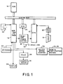
- the electronic postal meter 130 includes an 8-bit microprocessor 10 (FIG. 1) (CPU), such as an Intel Model 8085A microprocessor which is connected to various electronically operable components through a system bus 12, including a ROM 14.
- the RAM portion of the integrated circuit 16 has memory allocated for transient storage of the data for the ascending register and descending register.
- An external data communication port 18 which is connected to the microprocessor 10 through an optical isolator 20, allows for the connection to the postal meter of devices such as an electronic scale, external computer various types of servicing equipment and the like. Also electrically connected to the microprocessor 10 through the system bus 12 is the keyboard 22 of the postal meter and a non- volatile memory (NVM) 24.
- NVM non- volatile memory
- the bank and digit stepper motors 26, 28 of the postal meter are in electrical connection with the microprocessor 10 via a motor driver 30 and the integrated circuit 16.
- a reset and power control 32 is electrically connected between the integrated circuit 16, the NVM 24 and the microprocessor 10.
- a relay 34 connects the AC printer motor 36 to the integrated circuit 16.
- a display 38 is also electrically connected to the integrated circuit 16.
- the display 38 includes a plurality of, and preferably ten or less, seven segment (with decimal) digit display sections. And, for the purpose of this disclosure each decimal shall be considered to be a segment.
- a trip photosensor 40 which is connected to the microprocessor 10 through the integrated circuit 16, is provided for indicating the presence of an envelope to be imprinted, as described more fully in the aforementioned patent application entitled "Stand-Alone Electronic Mailing Machine".
- the electronic postage meter is controlled by the microprocessor 10 operating under control of the programs stored in the ROM 14.
- the microprocessor 10 accepts information entered via the keyboard 22 or via the external communication port 18 from external message generators.
- Critical accounting data and other important information is stored in the non-volatile memory 24.
- the non-volatile memory 24, which may be an MNOS semiconductor type memory, a battery augmented CMOS memory, core memory, or other suitable non-volatile memory component, stores critical postal meter data during periods when power is not applied to the postal meter.
- This data includes, in addition to the serial number of the mailing machine or postal meter, information as to the value in the descending register (the amount of postage available for printing), the value in the ascending register (the total amount of postage printed by the meter), and the value in the piece count register (the total number of cycles the meter has performed), as well as other types of data, such as trip status, initialization and service information, which are desired to be retained in the memory even though no power is applied to the postal meter.
- the microprocessor 10 When an on/off power switch 42 is turned on (closed) a power supply internal to the mailing machine energizes the microprocessor 10 and the balance of the electronic components. Whereupon information stored in the non-volatile memory 24 is copied into the RAM by the microprocessor 10. Accordingly, after power up the RAM contains an image or copy of the information which was stored only in the non-volatile memory 24 prior to energization.
- certain portions of the data in the RAM are ordinarily modified. For example, whenever postage is printed, the value stored in descending register will be reduced by the value of the printed postage, the value in the ascending register will be increased by the value of the printed postage and the value stored in the piece counter register will be incremented.
- the updated data reflecting such changed values in the RAM is transferred via the microprocessor 10 back into a suitably prepared area of the non- volatile memory 24. A like transfer of information between the non-volatile memory 24 and the RAM takes place during power failure.
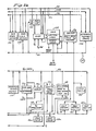
- FIG. 2 a more detailed block diagram of the arrangement of the electrical components of the postage meter is illustrated generally as 48.
- Power is supplied to the postage meter from the AC line voltage, typically 115 volts.
- This line voltage is applied to the meter through a hot switch 50 which cuts off power to the postage meter to protect the electrical components thereof if the temperature rises above a preset limit, nominally 70°C.
- the hot switch 50 is connected to the AC drive motor 36A through an RF filter 52 and an opto-triac 54 which provides isolation between the line voltage and the control logic for the meter.
- the hot switch 50 is also suitably connected to a transformer 56 protected by a fuse 58.
- the output of the transformer 56 is coupled to a pre-regulator 59 through a cold switch 60.
- the cold switch 60 cuts off power to the pre-regulator 59 if the temperature drops below a preset limit, nominally 0°C.
- the pre-regulator 59 provides an output voltage of a predetermined range to a switcher 62 which generates the output voltage +5V; and the voltages for generating -12V and -30V.
- the +5V is applied to a +3 volt regulator 64 and then to the display 38A.
- the +5V from the switcher 62 is also applied to a +5V filter 66 which provides +5V for logic circuits.
- the +5V is applied to the keyboard 22A, the display board 38A, and bank, digit and trip sensor logic 68 and to the integrated circuits.
- the -12V is applied to a -12V regulator 70 and then to the non- volatile memory 24A.
- the -30V output from the switcher 62 is also applied to a -30V regulator 74 and then to a -30V switch 76 which switches its output voltage on and off in response to the requirements of writing in NVM as dictated by a program.
- the output of the -30V switch is applied to the non-volatile memory 24A.
- the -30V supply is connected to the power on reset 72 of the microprocessor 10A.
- +5V from the switcher 62 is also supplied to one input of the power on reset 72; the other input receives -30V from the regulator 74 as previously described.
- a low voltage sensor 88 also receives one input of +5V from the switcher 62 and its other input from the pre-regulator 59 the output of the voltage sensor 88 is applied to the microprocessor 10A.
- the low voltage sensor 88 detects power failure and communicates this to the microprocessor 10A' which in turn addresses the RAM through system bus 12A to transfer all security data present in the RAM to the non-volatile memory 24A.
- Another output from the pre-regulator 59 in the form of +24V is applied to the digit and bank motor drive 30A for the bank motor 26A and digit motor 28A, which respectively select the particular printing wheel (bank) which is to be activated and the particular digit of the selected printing wheel which is to be set.
- An output strobe from the integrated circuit 16A is buffered through buffer driver 68 and applied to a digit sensor (encoder) 78, bank sensor (encoder) 80, and trip sensor 40A.
- the opto strobe applies power to the digit sensor 78, bank sensor 80 and trip sensor 40A when needed.
- the output from the trip sensor 40A is applied to the input/output lines 82 which are coupled to the integrated circuit 16A.
- the outputs from the digit sensor 78 and bank sensor 80 and cycle switch 84 are applied to a storage buffer 86.
- Initialization may include a hard and/or soft initialization' process as disclosed in the aforementioned U.S Patent No. 4,301,507.
- the initialization process for the mechanical components of the meter/machine is as disclosed in the aforementioned patent application entitled "Initializing The Print Wheels In An Electronic Postage Meter”.
- the microprocessor 10A under control of the ROM 14A and possibly the auxiliary ROM 100 communicates over the address bus 94 and control bus 98 with the device select 98.
- the output of the device select 98 communicates with the particular component to be addressed over select lines 99, including the RAM, the ROM 14A, an auxiliary ROM 100, a demultiplexer 102, NVM logic 104 and the buffer 86.
- the RAM of integrated circuit 16A provides the working memory for the postage meter and the microprocessor 10A.
- the ROM 14A stores the program; the auxiliary ROM 100 may be used to provide additional program storage space.
- the non-volatile memory 24A provides storage of all security information for the meter and retains such information during power down or power failure.
- the demultiplexer 102 latches the lower eight (8) bits of address information that defines a particular location which is used immediately thereafter.
- the NVM logic 104 controls the mode of operation of the NVM 24A and also provides ready, wait and NVM ready signals to the microprocessor 10A to indicate the presence of the slow speed device (NVM) as active on the bus 12A.
- NVM slow speed device
- the digital sensor 78 (optical encoder) and bank sensor 80 (optical encoder) and cycle switch 84 whose current state is read, i.e., "Home” or "In Cycle", apply input signals to the buffer 86 which sends output signals over data bus 108 to the microprocessor 10A for storage in the proper RAM location.
- the RAM is also electrically coupled to the I/O lines to transmit receive data from the trip sensor 40A, the display 38A, keyboard 22A, and, if present, a privileged access switch 110 which is kept under seal.
- the switch 110 is provided for use in applications which require manual resetting of meter postage by authorized personnel of, for example, the Postal Service.
- a mailing machine 130 adapted to house the aforesaid electronic postal meter includes a cover 132 having a hinged lid 134, and a slot 136 therein with a closed end 138 at the right hand side thereof. A portion of the slot 136 forms a deck 137 on which an envelope is placed when inserted into the slot 136 for printing postage thereon.
- At the top of the cover 132 is an opening 140, and a control panel 142 having a plurality of openings 143 formed therein.
- the cover 132 (FIF. 4) has nested therein an electromagnetic insulating shield 144.
- the cover 132 and shield 144 are attached to a base 146; the cover 132 and base 146 together forming a housing.
- the base 146 Depending from the base 146 is a pan 148 that contains a logic board 149. A power supply board 150 is mounted on the base 146.
- the display 38 and the keyboard 22 are conventionally supported within the housing, with the display 38 aligned with the opening 140 in the cover 132.
- the keyboard 22 (FIG. 5), which serves as an information inputting and information retrieval device, has a plurality of keys which extend through the openings 143 of the control panel 142 for access by the operator.
- Such keys include the numeric setting keys 156 numbered 0-9, a clear key 158, a decimal key 160, a postage used key 162, a postage unused key 164, a piece count key 166 and a select postage key 168.
- a plurality of special purpose keys of the keyboard 22 Such keys including an access code key 170 an enter amount key 172 an enter combination key 173 and a date key 174. Also located under the lid 134 are a plurality of thumbwheels 175 which are mechanically connected to the date printing mechanism for adjustment thereof as described more fully in the aforementioned application entitled "Stand-Alone Electronic Mailing Machine".
- the keys of the keyboard 22 are membrane switches.
- the electronic communication system of the postal meter is in many respects the same as the system disclosed in the aforesaid U.S. Patent No. 4,301,507.
- the software architecture of the communication system disclosed in Patent No. 4,301,507 services three separately compartmented units of electronic structure, referred to as the control unit, accounting unit and printing unit.
- Each of such units includes a dedicated central processing unit connected by way of conventional data lines, control lines and address lines to, in the case of the control unit, a multipurpose conventional RAM/ROM/I/O timer circuit incorporating timing control elements and input/output interface hardware, in the case of the accounting unit, a conventional EAROM and a plurality of PROMs incorporating timing control elements and input/output interface hardware, and, in the case of the printing unit, conventional buffers, timing control elements and input/output interface hardware. And, communications between the three units are conducted via serial channels connected between the respective microprocessors of the control, accounting and printing units.
- the functionally comparable units of electronic structure although not compartmented from each other are treated and function as separate and independent structures.
- the ROM 14 is organized for storing three substantially independently functioning sets of routines, one for each of the control, accounting and printing functions.
- the serial channel communication lines between the compartmented units of the prior art have been eliminated, the RAM of the integrated circuit 16 includes dedicated control, accounting and printing registers for communication between the three functional modules, and includes dedicated buffers for communications with external devices. Accordingly, information is communicated in message form between the three functional modules and between the mailing machine 130 and any external device connected to the external ports 18.
- control structure includes the circuits of the integrated circuit 16.
- the control routines utilize two buffers in the RAM, one in which messages corresponding to the digits of the display are built and stored, and the other in which a bit for bit copy or image of displayed digits is stored.
- a copy of such information in numerical message format is built in the display buffer and transferred in bit format to the image buffer for driving the display.
- the postal meter responds to any message from the keyboard 22, the response is communicated to the external device from the transmit buffer. And, with the exception of status responses any message stored in the transmit buffer is copied from the transmit buffer into the display buffer.
- the display is mainly used for displaying responses to entries from the keyboard 22.
- the keyboard 22 is utilized for inputting information to the microprocessor 10, which interprets each switch closure and in response thereto drives the display 38.
- the control structure is responsive to the application of power via the power supply board 150 to the mailing machine 130, for selectively energizing the LED display to visually display a predetermined code, which is preferably a single segment in the middle, or minus sign position, in the extreme left digit position of the LED display, and to concurrently intermittently flash the entire display until the lid 134 is opened and the date key 174 depressed.
- a predetermined code which is preferably a single segment in the middle, or minus sign position
- control structure is selectively responsive to utilization of the appropriate numerical keys 156 in combination with the access code key 170 for generating command and request messages for which separate keys have not been provided, for example a command to enter or exit the service mode.
- control structure is selectively responsive to utilization of the remote resetting keys, including the enter amount key 172 and enter combination key 173, for generating data entry messages which invoke various accounting routines for modifying values stored in the RAM to conform to customer requests, for example, for modifying the settable limit value, low postage warning value and dollar unlock value.
- provision is made for modifying the serial number of the postal meter if it is stored in the postal meter in modifiable form.
- control structure is selectively responsive to utilization of the access code key 170, enter amount key 172 and enter combination key 174 for generating data entry messages which invoke various accounting routines for, in the case of the access code key 170, displaying an access code which is used by the operator for calling into a Data Center to obtain a combination code, and in the case of the enter amount and enter combination keys, 172 and 174, for modifying (normally increasing) the postage unused value stored in the RAM to permit the postal meter to print additional postage.
- the accounting structure includes the non-volatile memory 24 for storing critical data, including the serial number, current values in the ascending and descending and piece count registers.
- the accounting structures also includes volatile memories, including a plurality of registers in the RAM which function as working ascending, descending and piece count registers for storing total amounts that are appropriately adjusted whenever postage is printed or the remote resetting function keys are utilized.
- the working volatile memories store such critical operational data for current use and transfer the same to the nonvolatile memory 24 at such time as a reduction in power is sensed or the main power switch 42 is moved to its off position.
- the printing structure includes the circuits of the optical sensors, 78 and 80, which are respectively associated with the digit and bank selector stepper motors 28 and 26, respectively, for sensing the relative positioning of the print wheels of the postal meter. And the printing structure also includes the circuits of the photosensor 40 associated with the trip lever for sensing the movement of the lever in response to appropriate insertion of an envelope into the mailing machine slot 136 as discussed more fully in the aforesaid patent application entitled "Stand-Alone Electronic Mailing Machine".
- the microprocessor 10 executes a scan routine under the control of the idle loop program.
- the scan routine continuously searches the keyboard 22 for key closures resulting from depression of keys.
- the microprocessor 10 executes a control routine which causes a subroutine stored in the control structure to drive the LED display in response to such key depressions.
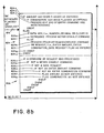
- the postal meter/mailing machine flags the date key as not checked 602. Thereafter, in the course of the initialization process, a zero postal value is displayed and flagged as a postage setting being on display 604. Whereupon, according to the invention, the date check logic routine of Fig. 6 is invoked.
- the microprocessor executes the program starting from idle 606, commencing with a determination as to whether or not the date has been checked 608. If it is not, the postal meter is disabled 616 and flagged as such, as a result of which the postal meter cannot print postage. If it were, determinations would also be made as to whether or not sufficient funds are available in the meter to print the displayed value 610, whether or not the postal meter is in the normal mode of operation 612, and whether or not the dollar unlock value stored in the meter is greater than the postage value which is displayed 614.
- the remainder of the organization of the check date logic routine calls for processing precedence to be given in turn to transmitting messages to the external device which are stored in the transmit buffer 618, then to processing messages generated by the external device and stored in the receiving buffer 624 and then to processing messages generated by the keyboard 628.
- processing precedence to be given in turn to transmitting messages to the external device which are stored in the transmit buffer 618, then to processing messages generated by the external device and stored in the receiving buffer 624 and then to processing messages generated by the keyboard 628.
- the transmit buffer is initially scanned to determine whether it is full or empty 618. If it is full, then, as shown in the first block 620, the message stored in the transmit buffer is transmitted to the external device 620a, the transmit buffer is flagged as empty 620b and processing returns to idle 606. Thereafter the microprocessor scans the various flags to determine whether status information has been queued 622, that is, has been flagged to indicate that it is information which is to be transmitted to the external device. If status has been queued, a message corresponding to the status of the postage meter is built in the transmit buffer 622a, for example a message including a bit which indicates the status of the date as not being checked, and the transmit buffer is flagged as full 622b. Whereupon processing returns to idle 606.
- the transmit buffer On the next scan, since the transmit buffer is now flagged as full 618, the message stored in the transmit buffer is transmitted to the external device 620a and the transmit buffer is again flagged as empty 620b and processing returns to idle 606. The aforesaid processing continues until all of the queue flags have resulted in a message being transmitted to the external device, one for each such queue flags. At this juncture, the transmit buffer having been flagged as empty, is available for filling with subsequent data to be transmitted, and processing returns to idle 606.
- the receiving buffer is flagged as full 624, the check date message stored therein is processed provided the postal meter is not in the service mode of operation 626b, 626g. Date check processing does not occur in the service mode because the postal meter is not equipped to process and account for printed postage when it is in the service mode. Also, in the case of a meter enable message being processed 626h, processing is ended if the meter is in the fatal mode of operation. This occurs when, for example, the meter has experienced a malfunction requiring the attention of a qualified serviceman. If the receiving buffer is flagged as empty 624, processing occurs in the fourth block 628, wherein keyboard generated messages 628a, pertaining to the postage setting being on display 628c, are processed.
- the meter is disabled 616 and flagged as such. Thereafter assuming the transmit buffer 618 and receive buffer 624 are both flagged as empty, processing occurs in the fourth block 628. If none of the keys 628a or 628b have been depressed, since the postage setting (zero value) is still flagged as on display 628c (from 604) and the date is still flagged as checked 628d (from 602), the check date indicator, preferably a minus sign in the extreme left digit position of the LED display, is turned on 628e and the entire LED display is set to a flashing mode of operation 628f.
- the operator would at this juncture check the setting of the date and change the same, if necessary, by manipulating the thumbwheels 175 (FIG. 3). Thereafter, the operator would depress the date key 174. Upon doing so, the date will not as yet have been checked 608 (FIG. 6). Accordingly, the meter would remain disabled 616 and flagged as such. On the other hand, since the transmit buffer is flagged as empty 618, the receiving buffer flagged as empty 624 and the check date key has been depressed 628a, the date is then flagged as checked 628i.
- the meter is enabled and flagged as such.
- the external device would normally be operated to generate and transmit to the postal meter a "reset check date" message, i.e., a header only message which simulates the depression of the date key of the postal meter. Assuming this has occurred, the transmit buffer is flagged as full 624, and the message processed. Since the postal meter is not in the service mode 626b and the message was "reset check date" 626c, the date is flagged as checked 626d, the receiving buffer is flagged as empty 626f and processing returned to idle 606.
- a "reset check date” message i.e., a header only message which simulates the depression of the date key of the postal meter.
- the transmit buffer is flagged as full 624, and the message processed. Since the postal meter is not in the service mode 626b and the message was "reset check date" 626c, the date is flagged as checked 626d, the receiving buffer is flagged as empty 626f and processing returned to idle 606.
- the meter Since the date has now been flagged as checked 608 (from 626d), and the questions 610, 612 and 614 are all answered affirmatively, the meter is enabled and flagged as such. Thereafter, all queued status is processed as hereinbefore discussed and transmitted to the external device. Then, since the date is flagged as checked (from 626d) and the setting is still flagged as on display 628c, the check date minus bit indicator is turned off 628g, the LED display set for the non-flashing mode 628h, and processing returned to idle 606.
- the external device can enable the meter 626j by transmitting an enable; meter message to the postal meter. Assuming this occurs and the postage setting on display 614 is greater than the dollar unlock value, the receiving buffer will be flagged as full 624 and the message therein processed in block 626. Whereupon if the mode is not service or not fatal 626g and the date is flagged as checked 626i, the enabled meter message will be processed, preferably, on an unconditional basis. However it is within the scope of the invention to conditionally enable the meter 626j. This may be deemed to be a desirable occurrence due to it being generally impermissable to unconditionally enable the meter 626j when the postage value on display exceeds the dollar unlock value 614. For example, it may be desirable that the processing step 626j include a conventional subroutine to permit enablement of the postal meter by the external device when the enable meter message 626h simulates more than one discrete depression of the select postage key.
- the postal meter may be enabled from the keyboard by depressing the select postage key 628b.
- the meter will be, preferably, unconditionally enabled.
- it may be desirable to conditionally enable the postage meter, for example if the postage setting on display exceeds the dollar lock value.
- the date is flagged as not checked, as a result of which the check date program is invoked and executed by the microprocessor to determine whether or not a postage setting is on display and, if it is and the date is not checked, the microprocessor disables the meter to prevent postage from being printed.
- the display is then driven to display at least one segment in a predetermined digit position of the display. In the preferred embodiment, a minus sign is displayed in the extreme left digit position.
- the entire LED display commences flashing, intermittently, to inform the user that the date has not been checked.
- the postal meter/ machine is programmed to respond to depression of the date key to turn off the minus sign bit in the extreme left hand digit position of the LED display and set the LED display to a non-flashing mode.
- the postal meter/ machine is programmed to respond to messages from an external device for simulating depression of the date key and for enabling the meter/ machine without operator intervention.
- the postal meter is programmed to permit utilization of the select postage key for generating an enable meter message after the date has been checked although the postage setting on display exceeds the dollar unlock value; and provision is made to permit an external device to simulate such operation of the postage meter.
- depression of the postage used key 162 effects the display at the display panel 140 of the total value in the ascending register of all postage that has been printed
- depression of the postage unused key 164 effects the display of the total value in the descending register of the postage then available for printing
- depression of the piece count key 166 effects the display of the total oount of all printing operations of the mailing machine 130.
- the depression of the selected key results in the current value associated with the key being displayed for a predetermined time interval after the key is released, for example several seconds, after which time interval the display will return to the then current postage setting.
- the numerical keys 156 in combination with the access code key 170 (FIG. 3) may be used for displaying the aforesaid information and other information which is not ordinarily the kind of information that a customer needs or is able to interpret.
- the postage used, postage unused and piece count keys, 162, 164 and 166 may each be used to effectuate the display of some of such other information. The latter case is hereinafter initially discussed since it exemplifies both usages of the keyboard.
- a predetermined numerical code having at least two and preferably four characters without a decimal, is entered in the keyboard 22 by depressing the appropriate numerical keys 156 (FIG. 5), followed by depression of the access code key 170 (FIG. 3).
- a control routine is invoked which causes the generation of a request or command header corresponding to the two low order digits in the display. For example, although a service mode key has not been provided, entering the numerals 6946 in the keyboard followed by depression of the access code key 170 will cause the generation of a "46" command header.
- the microprocessor will invoke a conventional subroutine causing the meter to enter the service mode of operation.
- a predetermined code preferably consisting of a segment inserted in the low segment position of each blank digit position will be displayed to inform the user that the postal meterand thus the machine is in the service mode of operation.
- depression of the postage used key 162 will result in the display of the "dollar unlock" value, consisting of a predetermined value which if equaled or exceeded, in the course of use of the postal meter, will not be printed unless the operator depresses the select postage key a second time after the value is originally displayed.
- the depression of the postage unused key 164 will result in the display of the "low postage warning" value, consisting of a predetermined postage value which results in the display of a warning signal informing the operator that the postal meter/mailing machine should be recharged.
- depression of the piece count key 166 will result in a diagnostic status display identifying the last fatal condition that occurred, even though that condition was subsequently cleared.
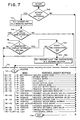
- FIG. 7 For the general case of usage of the numerical keys in combination with the access key 170 (FIG. 3) for displaying all of the above referred to information and still further information, reference is made to FIG. 7, wherein the 700 series of numbers are utilized to identify the steps of processing.
- the microprocessor under the direction of the idle loop program continues its idle routine.
- the access key is depressed 710, a single byte header message corresponding to the numerical value of "40" is built and stored in an available working buffer712. If there is no key entered data in the display 714 at this juncture, the microprocessor invokes the header message execution routine 716 shown below the dashed line in FIG. 7 to execute the header message 718.
- a "request access code” message is generated, which message results in the microprocessor invoking a conventional subroutinefor building an access code in the display buffer.
- the display buffer is copied into the image buffer in bit format for driving the LED display, as a result of which the access code is displayed to the operator, i.e., the code ordinarily used by the operator, for example for calling into Pitney Bowes Data Center, when charging the postal meter with additional postage.
- the aforesaid numeral 40 header is generated 712 and set in the available buffer, if there is key entered data is in the display 714 the header will not be executed.
- the display buffer will be scanned, and, if the data in the display buffer is not a four character display without a decimal 720, then the microprocessor invokes a conventional sub-routine which generates a "procedural error" message, i.e., a meter status message having a procedural error bit, which message is transferred to the display image buffer to drive the LED display to displaythe notation "ERR".
- a "procedural error” message i.e., a meter status message having a procedural error bit
- the microprocessor invokes the aforesaid sub-routine to generate the procedural error message and display the same error notation.
- the microprocessor invokes the header message execution routine 716 below the dashed line in FIG. 37 and execute the same to generate a message corresponding to the last two digits.
- header message routine 716 Upon execution of the header message routine 716 (FIG. 7), if the aforesaid last two digit header message is "40", a "request access code” message is generated, resulting in the display hereinbefore discussed. If the two digit header message is "41” an “enable meter” message is generated, if it is “42” a “meter disable” message is generated, if it is “46” an “enter service mode” message is generated, if it is “47” an “exit service mode” message is generated, if it is “50” a "request status” message is generated, and if it is "51” a "request selection value” message is generated.
- the microprocessor invokes a conventional sub-routine which is executed by the microprocessor to cause the performance of the particular operation of the meter which corresponds to the message and to provide a display corresponding to the message. For example, when the message "request access code” and “procedural error” were respectively generated as hereinbefore discussed, an access code and the notation "ERR" were respectively displayed.
- the postal meter/mailing machine is also programmed to permit an operator, usually a factory trained serviceman, to modify or initially store various predetermined values in the mailing machine which effect its operational characteristics. These values include the settable limit value, low postage warning value and dollar unlock value, which are usually modified to comply with customer needs or preferences. According to the invention, for modifying such values the machine is initially put into the service mode of operation as hereinbefore discussed. Having done so it should be noted that since the access code key is not involved with modifying values stored in the meter, theflow chart of FIG. 7 is not hereinafter referred to in the following discussion.
- the operator may optionally check the values that are to be modified, by depressing the appropriate key 162, 164 or 166 (FIG. 5) to determine whether or not modification is necessary. Thereafter the operator ordinarily enters the new value to be stored into the keyboard 22, by depressing the appropriate numerical keys 156, which results in the display of the corresponding value, and then depressing the enter amount key 172 (FIG. 3), which results in the storage of the displayed amount and blanking the display. Either before or after entry of the new value, the operator may enter a predetermined combination, having at least one digit, into the keyboard by utilizing the numerical keys 156 (FIG.
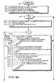
- the microprocessor automatically invokes the end of entry program shown in FIG. 8 for processing the entered amount and combination, as if an end of entry command had been received, thereby causing the value stored in the register identified by the combination to be changed to the new value.
- the end of entry program (Fig. 8) is executed by the microprocessor under the control of the appropriate accounting routine. As shown in FIG. 8, after power 810 is applied to the postal meter the receiving buffer is flagged as empty 812, the keyboard is flagged as enabled 814. In addition, the amount and combination working registers of the RAM are flagged as not entered, 816 and 818, in the course of initialization of the postal meter/ machine. Under the control of the idle loop program, the microprocessor then searches for executable instruction in the various working buffers of the RAM.
- processing precedence from idle 820 is given to messages received from external devices, over those that are internally generated.
- a request-to-send signal 822 has not been received from any external device since the initialization process was completed, and that the receiving buffer remains flagged as empty 812, the keyboard remains flagged as enabled 814, the amount remains flagged as not entered 816 and the combination remains flagged as not entered 818. Accordingly, messages are processed in accordance with the steps of the process set forth in the lower block 824 (FIG. 8).
- the amount and combination code are processed 824c as if an end of entry command has been received.
- processing is ended 824d. If however the amount has not been flagged as entered 824a and if a numerical data key is depressed 824e, then, the keyed data 824f generates a meter disable command.
- the abort analysis subroutine 826 shown below the dashed line in the lower block 826.
- this subroutine 826 if a command or request has been processed above the dashed line 826a, and if it was not a meter disable command 826b, and it was not a keyboard entered data request 826c i.e., a message generated as a result of depression of any one of the postage used, postage unused or piece count keys, and it was not an enter amount command 826d, and it was not an enter combination command 826e, then, the amount 826f and combination 826g are both flagged as not entered.
- the amount and combination, 826b, 826g are not flagged as not entered, or, otherwise stated, if one or the other of the amount or combination had been flagged as entered due to prior processing above the dashed line it will remain flagged as entered.
- the aforesaid abort analysis subroutine 826 (FIG. 8) is provided to be sure that once the operator commences the process of modifying one of the values stored in the postal meter, and certain other information other than the appropriate information for completing the value modification process is entered into the keyboard before completing the value modification process, then the operator is forced to recommence the value modification process. For example, if after the operator enters an amount, the operator then enters a postage value via the keyboard 824e, the meter will be disabled due to a meter disable command being generated and processed 824f each time a key is depressed. Such entries will not clear the amount and combination entry flags since a meter disable command was processed 826b.
- the message generated is a select postage command 826b not a data request .826c, not an enter amount command 826d and not an enter combination command 826e; as a result of which the amount and combination code will both be flagged as not entered.
- the previously entered amount will have to be reentered by the operator.
- the postage used key may be depressed for displaying the "dollar unlock” value
- the postage unused key may be depressed for displaying the "low postage warning” value
- the piece count key may be depressed for displaying the "diagnostic status"; these values, rather than those associated with the name of the key, being displayed since the new value/combination code is entered when the postal meter is in the service mode of operation.
- the amount and combination will not be flagged as not entered, since the depression of such keys results in generating a data request message and processing a data request message 826a results in ending the abort analysis subroutine. Accordingly, a previously entered amount or combination will not be flagged as not entered.
- the postal meter is programmed for forcing the operator to complete the value modification process after having commenced the same, or, otherwise stated, is programmed for preventing the value modification process from being aborted after its commencement, information which is relevant to value modification processing may be displayed after the process has been commenced with respect to any of the values that are ordinarily modified.
- the operator of an external device may take control of the meter to transmit a command or message by sending a request-to-send signal.
- the message associated with the signal will not be processed until internal processing then in progress is completed.
- the amount and combination are processed.
- the keyboard entry routine hereinbefore discussed was interrupted by a request-to-send signal 822 after entry of the amount and combination via the keyboard, the amount and combination would not be effected, since processing would have already automatically occurred as if an end of entry command had been received, inasmuch as the end of entry message associated with the request-to-send signal 822 will not be processed until the processing then in progress is completed.
- the incoming end of entry command 830a would find both the amount and combination flagged as not entered 830b and 830c, as a result of which processing of the end of entry command in the upper block diagram would be ended. This would also occur if the external device operator were to consecutively enter the amount and then enter the combination, in any order, unless the operator of the external device initially disables the keyboard. Assuming the external device is equipped to disable the keyboard, the operator of the external device has the option of allowing automatic processing, as previously discussed, as if an end of entry command had been sent, or, preventing such processing until an end of entry command is transmitted.
- commands and messages from the external device are also subjected to an abort analysis subroutine 831, in this instance as shown in the upper block 830.
- abort analysis subroutine 831 As shown below the dashed line 831, if a command or request was not a meter disable command 830a, not a numerical data request 830b, not an enter amount command 830c and not an enter combination command 830d, then, both the amount 830a and combination 830f are flagged as not entered.
- the request or command was a meter disable command 830a, or, if it was not, but was a data request 830b; or, if it was neither a meter disable command 830c nor a data request 830d but was an enter amount command 830e; or if it was not a meter disable command 830a nor data request 830b nor enter amount command 830c, but was an enter combination command 830d; then, in each instance, processing below the dashed line is ended and returns to idle 820.
- an end of entry command 830a must be sent from the external device to commence processing the amount and combination code if the operator of the external device initially transmitted a disable keyboard command; whereas, as shown in the lower block 824, an end of entry command need not be initiated by the operator to commence processing the amount and combination code data, rather it is automatically processed when the last of the two (amount or combination) are entered.
- the external operator has a choice of methodology which is unavailable to tne keyboard operator.
- the operator of the external device sends a disable keyboard command, it must be sent prior to entering either the amount or combination. For example, assuming the amount has been entered 830b but the combination has not been entered 830c and a disable keyboard command 831a a has not as yet been sent by the operator of the external device, if at this time a request to send signal 822 is sent, followed by a disable keyboard command 826, since this is not an end of entry command 830 it would be processed by the upper block 830 as any other command or request 830d and, in addition, the keyboard would be flagged as not enabled 830g.
- the keyboard disable command is not a meter disable command 831 a, and not a data request 830b, and not an enter amount command 830c and not an enter combination command 830d; the amount 830e and combination 830e will both be flagged as not entered. As a result, the previously entered amount would be cleared.
- the code is obtained from the Data Center by following the steps of depressing the access code key 170, which results in the display of a code" other' than the combination code, and then calling this code into the appropriate Data Center, as hereinbefore discussed, along with the serial number of the postal meter/ machine and the amount which is to be added to the postage unused register, to obtain from the Data Center the then current combination code which must be used for entry in order to effectu- ' ate modification of the value stored in the postage unused register.
- any modification of the serial number is ordinarily undertaken in the course manufacture of the machine and, in any event, before the machine is placed in service.
- the above discussed modification procedure can only be used for modifying the serial number if it is stored in modifiable form. For example, assuming the postal meter/mailing machine does not have a serial number or has a serial number which is to be modified; the foregoing procedure may be followed, utilizing as the new value, a serial number having at least one digit prefixed by a "zero" digit, for either initial entry or any modification of an unlocked serial number.
- the operator repeats the aforesaid modification procedure another time, utilizing the next previously entered serial number prefixed by a "one" digit rather than a "zero" digit, whereupon the microprocessor invokes a conventional subroutine which locks the next previously entered combination in place in the serial number register.
- postage meter and postal meter refer to the general definition of a device for the imprinting of a defined unit value for governmental or private carrier parcel, envelope or package delivery, or other like application for unit value printing.
- postal meter it is both known and employed in the trade as a general term for devices utilized in conjunction with services other than those exclusively employed by governmental postal services.
- private parcel or freight services purchase and employ postal meters as a means to provide unit value pricing for individual parcels, including acounting and printing functions.
Landscapes
- Physics & Mathematics (AREA)
- General Physics & Mathematics (AREA)
- Engineering & Computer Science (AREA)
- Computer Hardware Design (AREA)
- General Engineering & Computer Science (AREA)
- Devices For Checking Fares Or Tickets At Control Points (AREA)
- Management, Administration, Business Operations System, And Electronic Commerce (AREA)
- Polymerisation Methods In General (AREA)
- Photoreceptors In Electrophotography (AREA)
- Electrophonic Musical Instruments (AREA)
- Numerical Control (AREA)
Claims (68)
Priority Applications (1)
| Application Number | Priority Date | Filing Date | Title |
|---|---|---|---|
| AT83112360T ATE54765T1 (de) | 1982-12-08 | 1983-12-08 | Frankiermaschine mit einer tastatur mit tasten zum steuern und anfordern der durchfuehrung von frankiermaschinenoperationen. |
Applications Claiming Priority (2)
| Application Number | Priority Date | Filing Date | Title |
|---|---|---|---|
| US06/447,901 US4623987A (en) | 1982-12-08 | 1982-12-08 | Postage meter with keyboard keys for commanding and requesting performance of meter operations |
| US447901 | 1982-12-08 |
Publications (3)
| Publication Number | Publication Date |
|---|---|
| EP0111318A2 EP0111318A2 (fr) | 1984-06-20 |
| EP0111318A3 EP0111318A3 (en) | 1987-06-03 |
| EP0111318B1 true EP0111318B1 (fr) | 1990-07-18 |
Family
ID=23778188
Family Applications (1)
| Application Number | Title | Priority Date | Filing Date |
|---|---|---|---|
| EP83112360A Revoked EP0111318B1 (fr) | 1982-12-08 | 1983-12-08 | Machine à affranchir comportant des touches de clavier pour commander et demander l'exécution des opérations de la machine |
Country Status (7)
| Country | Link |
|---|---|
| US (1) | US4623987A (fr) |
| EP (1) | EP0111318B1 (fr) |
| JP (1) | JPH0743744B2 (fr) |
| AT (1) | ATE54765T1 (fr) |
| AU (1) | AU568102B2 (fr) |
| CA (1) | CA1222054A (fr) |
| DE (1) | DE3381747D1 (fr) |
Families Citing this family (6)
| Publication number | Priority date | Publication date | Assignee | Title |
|---|---|---|---|---|
| US4535407A (en) * | 1982-12-08 | 1985-08-13 | Pitney Bowes Inc. | Postage meter with keyboard keys for changing postage unused amount |
| US4713769A (en) * | 1985-09-11 | 1987-12-15 | Pitney Bowes Inc. | Method and apparatus for locating and displaying historical information within an electronic postage meter |
| US4843560A (en) * | 1986-10-16 | 1989-06-27 | Autostamp Institution Limited | Cost counter with a cost meter capable of reading stored data |
| FR2611946B1 (fr) * | 1987-02-27 | 1991-01-04 | Smh Alcatel | Machine a affranchir electronique comportant des valeurs limitant les affranchissements |
| US5357629A (en) * | 1991-09-16 | 1994-10-18 | Pitney Bowes Inc. | System for recording structured read only data table revisions and forming a directory to the latest revisions of table elements |
| US20030097346A1 (en) * | 2001-11-21 | 2003-05-22 | Peter Heimann | Control of franking machine from office programs |
Family Cites Families (17)
| Publication number | Priority date | Publication date | Assignee | Title |
|---|---|---|---|---|
| US2762298A (en) * | 1951-08-08 | 1956-09-11 | Pitney Bowes Inc | Date wheel setting device |
| US3938095A (en) * | 1971-11-04 | 1976-02-10 | Pitney-Bowes, Inc. | Computer responsive postage meter |
| US4097923A (en) * | 1975-04-16 | 1978-06-27 | Pitney-Bowes, Inc. | Remote postage meter charging system using an advanced microcomputerized postage meter |
| JPS52139338A (en) * | 1976-05-17 | 1977-11-21 | Casio Comput Co Ltd | Percent calculation system for cash register |
| AU506462B2 (en) * | 1976-07-05 | 1980-01-03 | Pitney-Bowes Inc. | Micro computerized electronic postage meter system |
| US4093999A (en) * | 1976-12-01 | 1978-06-06 | Vickers Limited | Electronic franking machines |
| JPS54128234A (en) * | 1978-03-17 | 1979-10-04 | Pitney Bowes Inc | Method of and device for supplying postal charge amount to meter |
| JPS5415635A (en) * | 1978-05-08 | 1979-02-05 | Sharp Corp | Cash register |
| JPS5813940B2 (ja) * | 1979-03-28 | 1983-03-16 | 東芝テック株式会社 | 電子レジスタにおけるモ−ド指定装置 |
| JPS55146507A (en) * | 1979-05-04 | 1980-11-14 | Hitachi Ltd | Initial state generating method of computer control system business |
| US4301507A (en) * | 1979-10-30 | 1981-11-17 | Pitney Bowes Inc. | Electronic postage meter having plural computing systems |
| US4285050A (en) * | 1979-10-30 | 1981-08-18 | Pitney Bowes Inc. | Electronic postage meter operating voltage variation sensing system |
| DE3126786C3 (de) * | 1980-07-14 | 1997-11-13 | Pitney Bowes Inc | Verbessertes fernbetätigtes Frankiermaschinen-Nachladesystem |
| JPS5771072A (en) * | 1980-10-20 | 1982-05-01 | Sharp Corp | Electronic computer |
| US4347506A (en) * | 1981-02-24 | 1982-08-31 | Pitney Bowes, Inc. | Electronic postage meter having check date warning with control for overriding the check date warning |
| US4628476A (en) * | 1982-12-08 | 1986-12-09 | Pitney Bowes Inc. | Completing an incomplete trip in an electronic postage meter |
| US4535407A (en) * | 1982-12-08 | 1985-08-13 | Pitney Bowes Inc. | Postage meter with keyboard keys for changing postage unused amount |
-
1982
- 1982-12-08 US US06/447,901 patent/US4623987A/en not_active Expired - Lifetime
-
1983
- 1983-11-25 AU AU21703/83A patent/AU568102B2/en not_active Ceased
- 1983-12-06 CA CA000442603A patent/CA1222054A/fr not_active Expired
- 1983-12-08 JP JP23220583A patent/JPH0743744B2/ja not_active Expired - Lifetime
- 1983-12-08 DE DE8383112360T patent/DE3381747D1/de not_active Revoked
- 1983-12-08 AT AT83112360T patent/ATE54765T1/de not_active IP Right Cessation
- 1983-12-08 EP EP83112360A patent/EP0111318B1/fr not_active Revoked
Non-Patent Citations (1)
| Title |
|---|
| Texas Instruments manual 1103893-0004D/D OM 729C189Sd, "Programmierbare TI-58/58C/59, Individuelles Programmieren" * |
Also Published As
| Publication number | Publication date |
|---|---|
| EP0111318A2 (fr) | 1984-06-20 |
| JPS59161766A (ja) | 1984-09-12 |
| JPH0743744B2 (ja) | 1995-05-15 |
| EP0111318A3 (en) | 1987-06-03 |
| AU568102B2 (en) | 1987-12-17 |
| AU2170383A (en) | 1984-06-14 |
| ATE54765T1 (de) | 1990-08-15 |
| US4623987A (en) | 1986-11-18 |
| CA1222054A (fr) | 1987-05-19 |
| DE3381747D1 (de) | 1990-08-23 |
Similar Documents
| Publication | Publication Date | Title |
|---|---|---|
| EP0131967B1 (fr) | Procédé et dispositif pour programmer, à la demande du client, le logiciel d'une machine d'affranchissement et machine d'affranchissement munie du logiciel ainsi programmé | |
| US4280180A (en) | Electronic postage meter having field resettable control values | |
| US4302821A (en) | Interposer control for electronic postage meter | |
| US4347506A (en) | Electronic postage meter having check date warning with control for overriding the check date warning | |
| GB2127745A (en) | Postage meter having interactive arithmetic operation capability | |
| GB2080588A (en) | Serial transmission system | |
| EP0111319B1 (fr) | Machine à affranchir comportant des touches de clavier pour le changement de valeur inutilisée de taxe postale | |
| EP0111315B1 (fr) | Machine d'affranchissement comportant des moyens de rappel de contrôle de date et procédé de fonctionnement de cette machine | |
| US4509141A (en) | Postage meter with keyboard keys used for changing operating constants | |
| EP0111316B1 (fr) | Dispositif et procédés pour contrôler des points de branchement firmware dans une machine d'affranchissement | |
| US4283721A (en) | Electronic postage meter having check date warning | |
| CA1150840A (fr) | Machine d'affranchissement postal pouvant effectuer des operations arithmetiques | |
| US4549281A (en) | Electronic postage meter having keyboard entered combination for recharging | |
| EP0111318B1 (fr) | Machine à affranchir comportant des touches de clavier pour commander et demander l'exécution des opérations de la machine | |
| US4577283A (en) | Postage meter with keyboard keys for causing meter operations to be performed | |
| US4739486A (en) | Modifying a firmware variable in an electronic postage meter | |
| EP0111317B1 (fr) | Procédé et dispositif pour modifier une variable firmware dans une machine à affranchir | |
| US4525786A (en) | Electronic postage meter having a one time actuable operating program to enable setting of critical accounting registers to predetermined values | |
| US4625282A (en) | Postage meter with keyboard keys for causing display of data pertaining to meter operation | |
| EP0111313B1 (fr) | Procédé et dispositif pour compléter un déclenchement imparfait dans une machine à affranchir électronique | |
| CA1147468A (fr) | Machine electronique d'affranchissement postal avec clavier pour introduire les donnees tarifaires | |
| US4266222A (en) | Electronic postage meter having reset base warning |
Legal Events
| Date | Code | Title | Description |
|---|---|---|---|
| PUAI | Public reference made under article 153(3) epc to a published international application that has entered the european phase |
Free format text: ORIGINAL CODE: 0009012 |
|
| AK | Designated contracting states |
Designated state(s): AT BE CH DE FR GB IT LI LU NL SE |
|
| RAP1 | Party data changed (applicant data changed or rights of an application transferred) |
Owner name: PITNEY BOWES INC. |
|
| PUAL | Search report despatched |
Free format text: ORIGINAL CODE: 0009013 |
|
| AK | Designated contracting states |
Kind code of ref document: A3 Designated state(s): AT BE CH DE FR GB IT LI LU NL SE |
|
| 17P | Request for examination filed |
Effective date: 19870723 |
|
| 17Q | First examination report despatched |
Effective date: 19880905 |
|
| GRAA | (expected) grant |
Free format text: ORIGINAL CODE: 0009210 |
|
| AK | Designated contracting states |
Kind code of ref document: B1 Designated state(s): AT BE CH DE FR GB IT LI LU NL SE |
|
| REF | Corresponds to: |
Ref document number: 54765 Country of ref document: AT Date of ref document: 19900815 Kind code of ref document: T |
|
| ITF | It: translation for a ep patent filed |
Owner name: STUDIO FERRARIO |
|
| REF | Corresponds to: |
Ref document number: 3381747 Country of ref document: DE Date of ref document: 19900823 |
|
| ET | Fr: translation filed | ||
| ITTA | It: last paid annual fee | ||
| PLBI | Opposition filed |
Free format text: ORIGINAL CODE: 0009260 |
|
| 26 | Opposition filed |
Opponent name: FRANCOTYP- POSTALIA GMBH Effective date: 19910418 |
|
| NLR1 | Nl: opposition has been filed with the epo |
Opponent name: FRANCOTYP- POSTALIA GMBH |
|
| EPTA | Lu: last paid annual fee | ||
| EAL | Se: european patent in force in sweden |
Ref document number: 83112360.9 |
|
| PLAB | Opposition data, opponent's data or that of the opponent's representative modified |
Free format text: ORIGINAL CODE: 0009299OPPO |
|
| R26 | Opposition filed (corrected) |
Opponent name: FRANCOTYP-POSTALIA GMBH Effective date: 19910418 |
|
| PGFP | Annual fee paid to national office [announced via postgrant information from national office to epo] |
Ref country code: SE Payment date: 19951110 Year of fee payment: 13 |
|
| PGFP | Annual fee paid to national office [announced via postgrant information from national office to epo] |
Ref country code: FR Payment date: 19951114 Year of fee payment: 13 Ref country code: AT Payment date: 19951114 Year of fee payment: 13 |
|
| PGFP | Annual fee paid to national office [announced via postgrant information from national office to epo] |
Ref country code: NL Payment date: 19951122 Year of fee payment: 13 |
|
| PGFP | Annual fee paid to national office [announced via postgrant information from national office to epo] |
Ref country code: CH Payment date: 19951123 Year of fee payment: 13 Ref country code: BE Payment date: 19951123 Year of fee payment: 13 |
|
| PGFP | Annual fee paid to national office [announced via postgrant information from national office to epo] |
Ref country code: GB Payment date: 19951124 Year of fee payment: 13 |
|
| PGFP | Annual fee paid to national office [announced via postgrant information from national office to epo] |
Ref country code: DE Payment date: 19951129 Year of fee payment: 13 |
|
| PGFP | Annual fee paid to national office [announced via postgrant information from national office to epo] |
Ref country code: LU Payment date: 19951201 Year of fee payment: 13 |
|
| PLAB | Opposition data, opponent's data or that of the opponent's representative modified |
Free format text: ORIGINAL CODE: 0009299OPPO |
|
| R26 | Opposition filed (corrected) |
Opponent name: FRANCOTYP-POSTALIA AKTIENGESELLSCHAFT & CO. Effective date: 19910418 |
|
| NLR1 | Nl: opposition has been filed with the epo |
Opponent name: FRANCOTYP-POSTALIA AKTIENGESELLSCHAFT & CO. |
|
| RDAG | Patent revoked |
Free format text: ORIGINAL CODE: 0009271 |
|
| STAA | Information on the status of an ep patent application or granted ep patent |
Free format text: STATUS: PATENT REVOKED |
|
| REG | Reference to a national code |
Ref country code: CH Ref legal event code: PL |
|
| GBPR | Gb: patent revoked under art. 102 of the ep convention designating the uk as contracting state |
Free format text: 960416 |
|
| 27W | Patent revoked |
Effective date: 19960416 |
|
| NLR2 | Nl: decision of opposition | ||
| APAH | Appeal reference modified |
Free format text: ORIGINAL CODE: EPIDOSCREFNO |
|
| PLAB | Opposition data, opponent's data or that of the opponent's representative modified |
Free format text: ORIGINAL CODE: 0009299OPPO |