EP0111218A2 - Electromagnet for NMR tomography - Google Patents
Electromagnet for NMR tomography Download PDFInfo
- Publication number
- EP0111218A2 EP0111218A2 EP83111745A EP83111745A EP0111218A2 EP 0111218 A2 EP0111218 A2 EP 0111218A2 EP 83111745 A EP83111745 A EP 83111745A EP 83111745 A EP83111745 A EP 83111745A EP 0111218 A2 EP0111218 A2 EP 0111218A2
- Authority
- EP
- European Patent Office
- Prior art keywords
- cylinder jacket
- dewar
- electromagnet according
- coil
- electromagnet
- Prior art date
- Legal status (The legal status is an assumption and is not a legal conclusion. Google has not performed a legal analysis and makes no representation as to the accuracy of the status listed.)
- Granted
Links
Images

Classifications
-
- G—PHYSICS
- G01—MEASURING; TESTING
- G01R—MEASURING ELECTRIC VARIABLES; MEASURING MAGNETIC VARIABLES
- G01R33/00—Arrangements or instruments for measuring magnetic variables
- G01R33/20—Arrangements or instruments for measuring magnetic variables involving magnetic resonance
- G01R33/28—Details of apparatus provided for in groups G01R33/44 - G01R33/64
- G01R33/38—Systems for generation, homogenisation or stabilisation of the main or gradient magnetic field
- G01R33/387—Compensation of inhomogeneities
- G01R33/3873—Compensation of inhomogeneities using ferromagnetic bodies ; Passive shimming
-
- G—PHYSICS
- G01—MEASURING; TESTING
- G01R—MEASURING ELECTRIC VARIABLES; MEASURING MAGNETIC VARIABLES
- G01R33/00—Arrangements or instruments for measuring magnetic variables
- G01R33/20—Arrangements or instruments for measuring magnetic variables involving magnetic resonance
- G01R33/28—Details of apparatus provided for in groups G01R33/44 - G01R33/64
- G01R33/38—Systems for generation, homogenisation or stabilisation of the main or gradient magnetic field
- G01R33/381—Systems for generation, homogenisation or stabilisation of the main or gradient magnetic field using electromagnets
- G01R33/3815—Systems for generation, homogenisation or stabilisation of the main or gradient magnetic field using electromagnets with superconducting coils, e.g. power supply therefor
-
- G—PHYSICS
- G01—MEASURING; TESTING
- G01R—MEASURING ELECTRIC VARIABLES; MEASURING MAGNETIC VARIABLES
- G01R33/00—Arrangements or instruments for measuring magnetic variables
- G01R33/20—Arrangements or instruments for measuring magnetic variables involving magnetic resonance
- G01R33/28—Details of apparatus provided for in groups G01R33/44 - G01R33/64
- G01R33/38—Systems for generation, homogenisation or stabilisation of the main or gradient magnetic field
- G01R33/387—Compensation of inhomogeneities
- G01R33/3875—Compensation of inhomogeneities using correction coil assemblies, e.g. active shimming
-
- G—PHYSICS
- G01—MEASURING; TESTING
- G01R—MEASURING ELECTRIC VARIABLES; MEASURING MAGNETIC VARIABLES
- G01R33/00—Arrangements or instruments for measuring magnetic variables
- G01R33/20—Arrangements or instruments for measuring magnetic variables involving magnetic resonance
- G01R33/28—Details of apparatus provided for in groups G01R33/44 - G01R33/64
- G01R33/42—Screening
- G01R33/421—Screening of main or gradient magnetic field
-
- Y—GENERAL TAGGING OF NEW TECHNOLOGICAL DEVELOPMENTS; GENERAL TAGGING OF CROSS-SECTIONAL TECHNOLOGIES SPANNING OVER SEVERAL SECTIONS OF THE IPC; TECHNICAL SUBJECTS COVERED BY FORMER USPC CROSS-REFERENCE ART COLLECTIONS [XRACs] AND DIGESTS
- Y10—TECHNICAL SUBJECTS COVERED BY FORMER USPC
- Y10S—TECHNICAL SUBJECTS COVERED BY FORMER USPC CROSS-REFERENCE ART COLLECTIONS [XRACs] AND DIGESTS
- Y10S505/00—Superconductor technology: apparatus, material, process
- Y10S505/825—Apparatus per se, device per se, or process of making or operating same
- Y10S505/842—Measuring and testing
- Y10S505/843—Electrical
- Y10S505/844—Nuclear magnetic resonance, NMR, system or device
Definitions
- the invention relates to an electromagnet for generating the static magnetic field for NMR tomography with a coil arrangement which consists of at least one circular cylindrical field coil and at least one correction coil concentric with the field coil and is surrounded by a ferromagnetic cylinder jacket, the influence of which on the homogeneity of the magnetic field generated by the coil arrangement in an interior defined by it, suitable and accessible for receiving the body to be examined is compensated for by the dimensioning of the field and correction coils.
- Such an electromagnet is the subject of the earlier patent application 82 10 3004.6.
- This electromagnet has a resistive coil arrangement.
- the invention consists in that the coil arrangement is superconducting and the ferromagnetic cylinder jacket surrounds the dewar containing the coil arrangement.
- a particularly compact design of the electromagnet according to the invention with a superconducting coil arrangement can be achieved in that in a further embodiment of the invention the cylinder jacket directly forms the outer wall of the Dewar.
- the effectiveness of the cylinder jacket as a shield and as a magnetic feedback can be further improved in that, in a further embodiment of the invention, the cylinder jacket is closed at the ends by annular, ferromagnetic plates which extend over the end faces of the Dewar. It goes without saying that these annular plates influence the configuration of the magnetic field generated by the coil arrangement and must be taken into account when dimensioning the coil arrangement.
- NMR tomography requires the creation of gradient fields of considerable strength, which have to be switched on and off very quickly.
- the resulting field changes cause eddy currents in the cylinder jacket.
- the cylinder jacket if appropriate including the ferromagnetic plates, from a material of high permeability and at the same time high electrical resistance. Special types of iron are available for this.
- the cylinder jacket can be slotted one or more times in the axial direction in order to avoid the formation of closed ring currents.
- the cylinder jacket can be composed of a large number of parallel rods. It can also be advantageous if the Cylinder jacket is slotted one or more times in the transverse direction.
- the cylinder jacket can be composed of a plurality of annular disks arranged axially one behind the other. In this way, eddy currents are avoided that have a pronounced axial component.
- the interruption of the magnetic circuit by the air gaps between the ring disks can be tolerated if the material and the wall thickness of the cylinder jacket are chosen accordingly.
- a combination of axial and transverse slots can be achieved in that the ring disks have at least one radial slot. If several radial slots are used, the ring disks are divided into sectors.
- cryo magnets A particular problem with the use of cryo magnets is the consumption of liquid helium and liquid nitrogen, which are required to generate the cryo temperatures. Since the cryo-magnet according to the invention is intended for continuous use, it is of particular importance to keep the consumption of liquid helium and nitrogen as small as possible.
- the dewar of the electromagnet can contain shields to which a cooling unit is connected. Such shields or intermediate plates, which are kept at low temperatures by means of the cooling unit, can significantly reduce the evaporation rate of the cryogenic liquids.
- the vessels containing the cooling liquids and also the shields arranged inside the dewar must have good thermal conductivity so that heat generated within the dewar is dissipated quickly and local heating cannot occur.
- Good heat-conducting materials generally also have good electrical conductivity.
- eddy currents can also occur in electrically conductive vessel walls and shields.
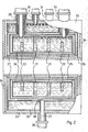
- the cryomagnet shown in FIG. 1 has a cylindrical field coil 1 and correction coils 2 and 3 arranged at the ends thereof, which concentrically surround the field coil 1.
- the coils 1 to 3 are arranged in a manner which is not shown in detail, but is known per se from conventional cryomagnets , within a cylindrical vessel 4 which has the shape of a double-walled tube section and is filled with liquid helium.
- This vessel 4 is surrounded by a gas-cooled shield 5 at a distance.
- a nitrogen shield 7 extends from the end faces of this vessel at a distance past the ends of the gas-cooled shield 5 and also surrounds the inner circumferential surface of this gas-cooled shield.
- the entire arrangement is surrounded by a non-magnetic Dewar 8.
- the individual vessels and interspaces between the vessel walls and the shields or the dewar are connected to lines for supplying and discharging helium, nitrogen and cooling gases via radially guided connecting pieces 9, 10, 11 and 12.
- a ferromagnetic shield which consists of a cylinder jacket 13 and annular plates 14 adjoining the ends of the cylinder jacket.
- the annular plates 14 have a central opening 15, the diameter of which is equal to the inner diameter of the tubular dewar 8.
- a collar 16 attached to the edge of the opening 15 is supported on the outer wall of the dewar 8.
- the ferromagnetic shield 13, 14 consists of an iron with high permeability and low electrical conductivity.
- the cylinder jacket 13 can be composed of individual annular disks 17, so that a large number of transverse slots are created which prevent the formation of axially directed eddy currents.
- the cylinder jacket 13 can also be constructed from a multiplicity of axially directed rods 18, as is illustrated in the lower half of FIG. 1. As a result, eddy currents extending in the circumferential direction of the cylinder jacket 13 are prevented.
- a combination of transverse and axial slots can be achieved by using ring disks which have an axial slot or are divided into a number of sectors in a manner not shown for the construction of the cylinder jacket.
- Ferromagnetic cylinder jackets of high stability can also be easily built from such slotted washers or sectors.
- the connection pieces 9 to 12 mentioned above are passed through the ferromagnetic cylinder jacket 13.
- the embodiment shown in FIG. 2 differs from the embodiment according to FIG. 1 on the one hand in the use of another coil arrangement and on the other hand in the use of the ferromagnetic shielding directly as the outer wall of the Dewar.
- 1 uses a coil arrangement which can essentially be regarded as a modified Garrett arrangement (Journal of Applied Physics, Vol. 40, No. 8 (July 1969), pages 3171 to 3179) is used in 2 a modified double Helmholtz arrangement. It consists of four coils arranged axially one behind the other, of which the two middle coils 21 have a larger diameter than the two outer coils 22.
- a modified Garrett arrangement Journal of Applied Physics, Vol. 40, No. 8 (July 1969), pages 3171 to 3179
- 2 a modified double Helmholtz arrangement. It consists of four coils arranged axially one behind the other, of which the two middle coils 21 have a larger diameter than the two outer coils 22.
- the coil arrangement is dimensioned here in such a way that in the one enclosed by it Space taking into account the ferromagnetic cladding a homogeneous magnetic field is generated.
- the coil arrangement is located in a vessel 24 filled with liquid helium, which is enclosed at a distance by a gas-cooled shield 25.
- This shield is connected to the outside again by a vessel 26 filled with liquid nitrogen with a nitrogen shield 27 also surrounding the gas-cooled shield 25 on the inner cylinder surface.
- this arrangement is directly surrounded by a ferromagnetic cylinder jacket 33, which at the same time forms the outer tubes of the pipe sockets 29, 30, 31, 32.
- the cylinder jacket 33 is again closed at its ends by ring-shaped, ferromagnetic plates 34 which extend up to the inside diameter of the nitrogen exhaust extend shielding 27.
- a central tube 35 is inserted, which is made of a non-magnetic material and limits the space available for receiving the object to be examined.
- the cylinder jacket 33 and the annular plates 34 are made of a highly permeable material with low electrical conductivity.
- the plates arranged at the ends of the cylinder jacket could also be constructed from rings or sectors in order to suppress eddy currents as far as possible in this area as well.
- the magnetic shield forms the outer wall of the dewar directly, the use of a solid cylindrical jacket 33 and solid annular plates 34 could be more expedient to avoid difficult sealing problems.
- the cryo-magnet shown in FIG. 2 is also provided with an additional cooling unit 36 which is in thermal contact with cooled fingers 37 and 38 with the wall of the vessel 26 filled with liquid nitrogen and with the gas-cooled shield 25.
- an additional cooling unit 36 which is in thermal contact with cooled fingers 37 and 38 with the wall of the vessel 26 filled with liquid nitrogen and with the gas-cooled shield 25.
- a dewar and the vessels and shields arranged inside the dewar are normally made of metal, because metal has the high thermal conductivity required to keep the thermal gradients occurring within the dewar small.
- metal has the high thermal conductivity required to keep the thermal gradients occurring within the dewar small.
- eddy currents can also arise in metallic vessel walls and shields, which result not only in energy loss, but also in the development of heat within the dewar. It is therefore necessary to keep the eddy currents caused by the switching of field gradients small within the cryogenic container.
- the components of the dewar located within the magnetic shield, the cooling vessels and the shields can consist of an electrically poorly conductive material, for example of glass fiber reinforced plastic.
- the plastic parts can have metal inserts which are designed and arranged in such a way that they do not form short-circuit paths for eddy currents, but nevertheless produce the desired good thermal conductivity.
Landscapes
- Physics & Mathematics (AREA)
- Condensed Matter Physics & Semiconductors (AREA)
- General Physics & Mathematics (AREA)
- Electromagnetism (AREA)
- Health & Medical Sciences (AREA)
- Epidemiology (AREA)
- Magnetic Resonance Imaging Apparatus (AREA)
- Soft Magnetic Materials (AREA)
- Apparatus For Radiation Diagnosis (AREA)
- Electromagnets (AREA)
Abstract
Description
Die Erfindung betrifft einen Elektromagneten zur Erzeugung des statischen Magnetfeldes für die NMR-Tomographie mit einer Spulenanordnung, die aus mindestens einer kreiszylindrischen Feldspule und mindestens einer zur Feldspule konzentrischen Korrekturspule besteht und von einem ferromagnetischen Zylindermantel umgeben ist, dessen Einfluß auf die Homogenität des Magnetfeldes, das von der Spulenanordnung in einem von ihr definierten, zur Aufnahme des zu untersuchenden Körpers geeigneten und zugänglichen Innenraumes erzeugt wird, durch die Dimensionierung der Feld- und Korrekturspulen kompensiert ist.The invention relates to an electromagnet for generating the static magnetic field for NMR tomography with a coil arrangement which consists of at least one circular cylindrical field coil and at least one correction coil concentric with the field coil and is surrounded by a ferromagnetic cylinder jacket, the influence of which on the homogeneity of the magnetic field generated by the coil arrangement in an interior defined by it, suitable and accessible for receiving the body to be examined is compensated for by the dimensioning of the field and correction coils.
Ein solcher Elektromagnet ist Gegenstand der älteren Patentanmeldung 82 10 3004.6. Dieser Elektromagnet hat eine resistive Spulenanordnung. Demgegenüber besteht die Erfindung darin, daß die Spulenanordnung supraleitend ist und der ferromagnetische Zylindermantel das die Spulenanordnung enthaltende Dewar umgibt.Such an electromagnet is the subject of the earlier patent application 82 10 3004.6. This electromagnet has a resistive coil arrangement. In contrast, the invention consists in that the coil arrangement is superconducting and the ferromagnetic cylinder jacket surrounds the dewar containing the coil arrangement.
Es hat sich gezeigt,.daß die Vorteile der Anordnung eines ferromagnetischen Zylindermantels, die einerseits in der Abschirmung störender äußerer Magnetfelder sowie auch in der Beschränkung des von dem Elektromagneten erzeugten Magnetfeldes sowie bei der Tomographie zu erzeugenden HF-Felder auf den vom Zylindermantel umschlossenen Bereich bestehen, voll erhalten bleiben, wenn der Zylindermantel das Dewar eines Kryo-Magneten umgibt. Ebenso wie beim resistiven Elektromagneten erlaubt auch beim Kryo-Magneten die Rückführung des Magnetflusses durch den ferromagnetischen Zylindermantel eine Verkleinerung der Spulenanordnungen, so daß der Platzbedarf für solche Elektromagneten gegenüber herkömmlichen Kry6-Magneten bedeutend vermindert wird. Gegenüber resistiven Elektromagneten hat auch bei der NMR-Tomographie die Verwendung eines Kryo-Magneten den besonderen Vorteil, daß die Temperaturkonstanz dieser Magnete die Erzeugung eines besonders stabilen und damit auch homogenen Magnetfeldes gestattet.It has been shown that the advantages of the arrangement of a ferromagnetic cylinder jacket exist, on the one hand, in the shielding of disturbing external magnetic fields, and also in the limitation of the magnetic field generated by the electromagnet, and in the case of RF fields to be generated in the tomography, to the area enclosed by the cylinder jacket , remain fully intact when the cylinder jacket surrounds the dewar of a cryo magnet. As with the resistive electromagnet, the return of the magnetic flux through the ferromagnetic cylinder jacket also allows the coil arrangements to be reduced in size in the case of the cryo-magnet, so that the space requirement for such electromagnets is significantly reduced compared to conventional Kry6 magnets. Compared to resistive electromagnets, the use of a cryo-magnet also has the particular advantage in NMR tomography that the temperature constancy of these magnets allows the generation of a particularly stable and thus also homogeneous magnetic field.
Eine besonders kompakte Bauweise des erfindungsgemäßen Elektromagneten mit einer supraleitenden Spulenanordnung kann dadurch erzielt werden, daß in weiterer Ausgestaltung der Erfindung der Zylindermantel unmittelbar die Außenwand des Dewar bildet.A particularly compact design of the electromagnet according to the invention with a superconducting coil arrangement can be achieved in that in a further embodiment of the invention the cylinder jacket directly forms the outer wall of the Dewar.
Die Wirksamkeit des Zylindermantels als Abschirmung und als magnetische Rückführung kann noch dadurch verbessert werden, daß in weiterer Ausgestaltung der Erfindung der Zylindermantel an den Enden durch ringförmige, ferromagnetische Platten abgeschlossen ist, die sich über die Stirnflächen des Dewar erstrecken. Es versteht sich, daß diese ringförmigen Platten die Konfiguration des von der Spulenanordnung erzeugten Magnetfeldes beeinflussen und bei der Dimensionierung der Spulenanordnung berücksichtigt werden müssen.The effectiveness of the cylinder jacket as a shield and as a magnetic feedback can be further improved in that, in a further embodiment of the invention, the cylinder jacket is closed at the ends by annular, ferromagnetic plates which extend over the end faces of the Dewar. It goes without saying that these annular plates influence the configuration of the magnetic field generated by the coil arrangement and must be taken into account when dimensioning the coil arrangement.
Die NMR-Tomographie erfordert die Erzeugung von Gradientenfeldern erheblicher Stärke, die sehr schnell zu- und abgeschaltet werden müssen. Die dadurch bedingten Feldänderungen verursachen Wirbelströme in dem Zylindermantel. Um diese Wirbelströme klein zu halten, ist es zweckmäßig, den Zylindermantel gegebenenfalls einschließlich der ferromagnetischen Platten aus einem Werkstoff hoher Permeabilität und gleichzeitig hohem elektrischem Widerstand herzustellen. Hierfür stehen besondere Eisensorten zur Verfügung. Zusätzlich kann der Zylindermantel in Achsrichtung ein- oder mehrfach geschlitzt sein, um das Entstehen geschlossener Ringströme zu vermeiden. So kann beispielsweise der Zylindermantel aus einer Vielzahl.achsparalleler Stäbe zusammengesetzt sein. Ebenso kann es vorteilhaft sein, wenn der Zylindermantel in Transversalrichtung ein- oder mehrfach geschlitzt ist. Insbsondere kann der Zylindermantel aus einer Vielzahl axial hintereinander angeordneter Ringscheiben zusammengsetzt sein. Auf diese Weise werden Wirbelströme vermieden, die eine ausgeprägte Axialkomponente aufweisen. Die Unterbrechung des magnetischen Kreises durch die Luftspalte zwischen den Ringscheiben kann bei entsprechender Wahl des Materials und der Wandstärke des Zylindermantels hingenommen werden. Eine Kombination von Axial- und Transversalschlitzen kann dadurch erzielt werden, daß die Ringscheiben wenigstens einen Radialschlitz aufweisen. Bei der Anwendung mehrerer Radialschlitze ergibt sich eine sektorförmige Unterteilung der Ringscheiben.NMR tomography requires the creation of gradient fields of considerable strength, which have to be switched on and off very quickly. The resulting field changes cause eddy currents in the cylinder jacket. In order to keep these eddy currents small, it is expedient to manufacture the cylinder jacket, if appropriate including the ferromagnetic plates, from a material of high permeability and at the same time high electrical resistance. Special types of iron are available for this. In addition, the cylinder jacket can be slotted one or more times in the axial direction in order to avoid the formation of closed ring currents. For example, the cylinder jacket can be composed of a large number of parallel rods. It can also be advantageous if the Cylinder jacket is slotted one or more times in the transverse direction. In particular, the cylinder jacket can be composed of a plurality of annular disks arranged axially one behind the other. In this way, eddy currents are avoided that have a pronounced axial component. The interruption of the magnetic circuit by the air gaps between the ring disks can be tolerated if the material and the wall thickness of the cylinder jacket are chosen accordingly. A combination of axial and transverse slots can be achieved in that the ring disks have at least one radial slot. If several radial slots are used, the ring disks are divided into sectors.
Ein besonderes Problem beim Einsatz von Kryo-Magneten besteht in dem Verbrauch an flüssigem Helium und flüssigem Stickstoff, die zur Erzeugung der Kryo-Temperaturen benötigt werden. Da der erfindungsgemäße Kryo-Magnet für den Dauereinsatz bestimmt ist, ist es von besonders hoher Bedeutung, den Verbrauch an flüssigem Helium und Stickstoff so klein wir nur irgend möglich zu halten. Zu diesen Zweck kann in weiterer Ausgestaltung der Erfindung das Dewar des Elektromagneten Abschirmungen enthalten, an die ein Kühlaggregat angeschlossen ist. Durch solche Abschirmungen oder Zwischenschilder, die mittels des Kühlaggregates auf Tieftemperaturen gehalten werden, kann die Verdampfungsrate der kryogenen Flüssigkeiten erheblich abgesenkt werden.A particular problem with the use of cryo magnets is the consumption of liquid helium and liquid nitrogen, which are required to generate the cryo temperatures. Since the cryo-magnet according to the invention is intended for continuous use, it is of particular importance to keep the consumption of liquid helium and nitrogen as small as possible. For this purpose, in a further embodiment of the invention, the dewar of the electromagnet can contain shields to which a cooling unit is connected. Such shields or intermediate plates, which are kept at low temperatures by means of the cooling unit, can significantly reduce the evaporation rate of the cryogenic liquids.
Die die Kühlflüssigkeiten enthaltenden Gefäße und ebenso die innerhalb des Dewar angeordneten Abschirmungen müssen gute Wärmeleitfähigkeit aufweisen, damit innerhalb des Dewars entstehende Wärme schnell abgeführt wird und es nicht zu örtlichen Erwärmungen kommen kann. Gut wärmeleitende Materialien haben in der Regel auch eine gute elektrische Leitfähigkeit. Ebenso wie bei dem Magnetmantel kann es aber auch in elektrisch leitenden Gefäßwandungen und Abschirmungen zu Wirbelströmen kommen. Die dadurch bedingten Schwierigkeiten lassen sich in weiterer Ausgestaltung der Erfindung dadurch vermeiden, daß das Dewar und/oder davon umschlossene Kühlgefäße, Abschirmungen u.dgl. wenigstens teilweise aus elektrisch schlecht leitenden und ggf. mit Einlagen guter Wärmeleitfähigkeit versehenen Materialien bestehen. Bei solchen Materialien, insbesondere glasfaserverstärkten Kunststoffen, handelt es sich um sowohl elektrisch nichtleitende als auch unmagnetische Materialien, die demgemäß die Funktion des Magneten in keiner Weise stören können. Insbesondere können in solchen Kunststoffteilen keine Wirbelströme entstehen. Die mangelnde Wärmeleitfähigkeit von Kunststoff kann durch die erwähnten Einlagen guter Wärmeleitfähigkeit, beispielsweise Kupfereinlagen, ausgeglichen werden, die so angeordnet und so unterteilt werden können, daß auch darin keine nennenswerte Ausbildung von Wirbelströmen mehr stattfinden kann.The vessels containing the cooling liquids and also the shields arranged inside the dewar must have good thermal conductivity so that heat generated within the dewar is dissipated quickly and local heating cannot occur. Good heat-conducting materials generally also have good electrical conductivity. As with the magnetic jacket, eddy currents can also occur in electrically conductive vessel walls and shields. The resulting difficulties can be avoided in a further embodiment of the invention in that the Dewar and / or cooling vessels, shields and the like enclosed by it. consist at least partially of materials that are poorly electrically conductive and possibly provided with inserts of good thermal conductivity. Such materials, in particular glass-fiber reinforced plastics, are both electrically non-conductive and non-magnetic materials, which accordingly can in no way interfere with the function of the magnet. In particular, no eddy currents can arise in such plastic parts. The lack of thermal conductivity of plastic can be compensated for by the above-mentioned deposits of good thermal conductivity, for example copper inlays, which can be arranged and subdivided in such a way that significant eddy currents can also no longer be formed therein.
Die Erfindung wird im folgenden anhand der in der Zeichnung dargestellten Ausführungsbeispiele näher beschrieben und erläutert. Die der Beschreibung und der Zeichnung zu entnehmenden Merkmale können bei anderen Ausführungsformen der Erfindung einzeln für sich oder zu mehreren in beliebiger Kombination Anwendung finden. Es zeigen:
- Fig. 1 einen Längsschnitt durch eine erste Ausführungsform eines supraleitenden Elektromagneten nach der Erfindung und
- Fig. 2 einen Längsschnitt durch eine zweite Ausführungsform eines solchen Kryo-Magneten.
- Fig. 1 shows a longitudinal section through a first embodiment of a superconducting electromagnet according to the invention and
- Fig. 2 shows a longitudinal section through a second embodiment of such a cryo magnet.
Der in Fig. 1 dargestelle Kryo-Magnet weist eine zylindrische Feldspule 1 und an deren Enden angeordnete Korrekturspulen 2 und 3 auf, welche die Feldspule 1 konzentrisch umgeben. Die Spulen 1 bis 3 sind in nicht näher dargestellter, jedoch von herkömmlichen Kryo-Magneten an sich bekannter Weise innerhalb eines zylindrischen Gefäßes 4 angeordnet, das die Form eines doppelwandigen Rohrabschnittes besitzt und mit flüssigem Helium gefüllt ist. Dieses Gefäß 4 ist mit Abstand von einer gasgekühlten Abschirmung 5 umgeben. An die Außenseite der Abschirmung 5 schließt sich ein weiteres rohrförmiges Gefäß 6 an, das mit flüssigem Stickstoff gefüllt ist. Von den Stirnflächen dieses Gefäßes erstreckt sich eine Stickstoff-Abschirmung 7 mit Abstand an den Enden der gasgekühlten Abschirmung 5 vorbei und umgibt auch die innere Mantelfläche dieser gasgekühlten Abschirmung. Endlich ist die gesamte Anordnung von einem unmagnetisehen Dewar 8 umgeben. Die einzelnen Gefäße und Zwischenräume zwischen den Gefäßwandungen und den Abschirmungen bzw. dem Dewar stehen über radial herausgeführte Anschlußstutzen 9,10, 11 und 12 mit Leitungen zum Zu- und Abführen von Helium, Stickstoff sowie Kühlgasen in Verbindung.The cryomagnet shown in FIG. 1 has a cylindrical field coil 1 and
Erfindungsgemäß ist der gesamte, bisher beschriebene Kryo-Magnet von einer ferromagnetischen Abschirmung umschlossen, die aus einem Zylindermantel 13 und sich an die Enden des Zylindermantels anschließenden, ringförmigen Platten 14 besteht. Die ringförmigen Platten 14 weisen eine zentrale Öffnung 15 auf, deren Durchmesser dem Innendurchmesser des rohrförmigen Dewars 8 gleich ist. Ein am Rand der Öffnung 15 angebrachter Bund 16 stützt sich an der Außenwand des Dewars 8 ab.According to the invention, the entire cryo-magnet described so far is enclosed by a ferromagnetic shield, which consists of a
Zur Unterdrückung von Wirbelströmen besteht die ferromagnetische Abschirmung 13, 14 aus einem Eisen mit hoher Permeabilität und geringer elektrischer Leitfähigkeit. Außerdem kann, wie in der oberen Hälfte von Fig. 1 dargestellt, der Zylindermantel 13 aus einzelnen Ringscheiben 17 zusammengesetzt sein, so daß eine Vielzahl von Transversalschlitzen entsteht, welche die Ausbildung axial gerichteter Wirbelströme verhindern. Stattdessen kann der Zylindermantel 13 auch aus einer Vielzahl axial gerichteter Stäbe 18 aufgebaut sein, wie es in der unteren Hälfte von Fig. 1 veranschaulicht ist. Hierdurch werden vor allem in Umfangsrichtung des Zylindermantels 13 verlaufende Wirbelströme unterbunden. Eine Kombination von Transversal- und Axialschlitzen kann dadurch erzielt werden, daß in nicht näher dargestellter Weise zum Aufbau des Zylindermantels Ringscheiben verwendet werden, die einen Axialschlitz aufweisen oder aber in eine Anzahl von Sektoren unterteilt sind. Auch aus solchen geschlitzten Ringscheiben oder Sektoren lassen sich ohne weiteres ferromagnetische Zylindermäntel hoher Stabilität aufbauen. Die oben erwähnten Anschlußstutzen 9 bis 12 sind durch den ferromagnetischen Zylindermantel 13 hindurchgeführt.To suppress eddy currents, the
Die in Fig. 2 dargestellte Ausführungsform unterscheidet sich von der Ausführungsform nach Fig. 1 einerseits in der Verwendung einer anderen Spulenanordnung und andererseits in der Verwendung der ferromagnetischen Abschirmung unmittelbar als Außenwand des Dewar. Während bei der Ausführungsform nach Fig. 1 eine Spulenanordnung Anwendung findet, die im wesentlichen als modifizierte Garrett-Anordnung betrachtet werden kann (Journal of Applied Physics, Bd. 40, Nr. 8 (Juli 1969), Seiten 3171 bis 3179), findet bei der Ausführungsform nach Fig. 2 eine modifizierte Doppel-Helmholtz-Anordnung Verwendung. Sie besteht aus vier axial hintereinander angeordneten Spulen, von denen die beiden mittleren Spulen 21 einen größeren Durchmesser haben als die beiden äußeren Spulen 22. Wie im Falle der Ausführungsform nach Fig. 1 ist auch hier die Spulenanordnung so dimensioniert, daß in dem von ihr umschlossenen Raum unter Berücksichtigung des ferromagnetischen Mantels ein homogenes Magnetfeld erzeugt wird. Auch hier befindet sich die Spulenanordnung in einem mit flüssigem Helium gefüllten Gefäß 24, das mit Abstand von einer gasgekühlten Abschirmung 25 umschlossen ist. An diese Abschirmung schließt sich wieder nach außen ein mit flüssigem Stickstoff gefülltes Gefäß 26 mit einer die gasgekühlte Abschirmung 25 auch an der inneren Zylinderfläche umgebenden Stickstoff-Abschirmung 27 an. Anstelle eines gesonderten Dewar ist diese Anordnung unmittelbar von einem ferromagnetischen Zylindermantel 33 umgeben, der zugleich die äußeren Rohre der Rohrstutzen 29, 30, 31, 32 bildet. Der Zylindermantel 33 ist wieder an seinen Enden durch ringförmige, ferromagnetische Platten 34 verschlossen, die sich bis über den Innendurchmesser der Stickstoff-Abschirmung 27 hinweg erstrecken. In die Öffnungen der ringförmigen Platten 34 ist ein zentrales Rohr 35 eingesetzt, das aus einem unmagnetischen Material besteht und den zur Aufnahme des zu untersuchenden Objektes zur Verfügung stehenden Raum begrenzt. Auch hier bestehen wieder der Zylindermantel 33 und die ringförmigen Platten 34 aus einem hochpermeablen Material mit geringer elektrischer Leitfähigkeit. Auch hier besteht grundsätzlich die Möglichkeit, den Zylindermantel 33 zu schlitzen. Gegebenenfalls könnten auch die an den Enden des Zylindermantels angeordneten Platten aus Ringen oder Sektoren aufgebaut sein, um auch in diesem Bereich Wirbelströme möglichst weitgehend zu unterdrücken. Allerdings könnte dann, wenn, wie bei diesem Ausführungebeispiel, die magnetische Abschirmung unmittelbar die äußere Wand des Dewars bildet, zur Vermeidung schwieriger Abdichtungsprobleme die Anwendung eines massiven Zylinäermantels 33 sowie massiver ringförmiger Platten 34 zweckmäßiger sein.The embodiment shown in FIG. 2 differs from the embodiment according to FIG. 1 on the one hand in the use of another coil arrangement and on the other hand in the use of the ferromagnetic shielding directly as the outer wall of the Dewar. 1 uses a coil arrangement which can essentially be regarded as a modified Garrett arrangement (Journal of Applied Physics, Vol. 40, No. 8 (July 1969), pages 3171 to 3179) is used in 2 a modified double Helmholtz arrangement. It consists of four coils arranged axially one behind the other, of which the two
Der in Fig. 2 dargestellte Kryo-Magnet ist noch mit einem zusätzlichen Kühlaggregat 36 versehen, das mit gekühlten Fingern 37 und 38 mit der Wandung des mit flüssigem Stickstoff gefüllten Gefäßes 26 sowie mit der gasgekühlten Abschirmung 25 in Wärmekontakt steht. Mit Hilfe des Kühlaggregates ist es möglich, einen erheblichen Teil der von außen in das System eindringenden Wärme abzuführen. Demgemäß kann durch die Anwendung eines solchen Kühlaggregates der Verbrauch an flüssigem Helium, an flüssigem Stickstoff oder anderen kryogenen Flüssigkeiten bedeutend gesenkt werden.The cryo-magnet shown in FIG. 2 is also provided with an
Normalerweise bestehen ein Dewar und auch die innerhalb des Dewars angeordneten Gefäße und Abschirmungen aus Metall, weil Metall eine hohe Wärmeleitfähigkeit besitzt, die erforderlich ist, um die innerhalb des Dewars auftretenden Wärmegradienten klein zu halten. Andererseits können auch in metallischen Gefäßwandungen und Abschirmungen Wirbelströme entstehen, die nicht nur einen Energieverlust zur Folge haben, sondern auch eine Wärmeentwicklung innerhalb des Dewars. Daher ist es notwendig, die durch das Schalten von Feldgradienten bedingten Wirbelströme auch innerhalb des Kryo-Behälters klein zu halten. Für diesen Zweck können die sich innerhalb der magnetischen Abschirmung befindenden Bauelemente des Dewars, die Kühlgefäße und die Abschirmungen aus einem elektrisch schlecht leitenden Material, beispielsweise aus glasfaserverstärktem Kunststoff bestehen. Um trotzdem nicht die notwendige gute Wärmeleitung zu beeinträchtigen, können die Kunststoffteile Metalleinlagen aufweisen, die derart beschaffen und angeordnet sind, daß sie keine Kurzschlußwege für Wirbelströme bilden, die erwünschte gute Wärmeleitfähigkeit jedoch herstellen.A dewar and the vessels and shields arranged inside the dewar are normally made of metal, because metal has the high thermal conductivity required to keep the thermal gradients occurring within the dewar small. On the other hand, eddy currents can also arise in metallic vessel walls and shields, which result not only in energy loss, but also in the development of heat within the dewar. It is therefore necessary to keep the eddy currents caused by the switching of field gradients small within the cryogenic container. For this purpose, the components of the dewar located within the magnetic shield, the cooling vessels and the shields can consist of an electrically poorly conductive material, for example of glass fiber reinforced plastic. In order not to impair the necessary good heat conduction, the plastic parts can have metal inserts which are designed and arranged in such a way that they do not form short-circuit paths for eddy currents, but nevertheless produce the desired good thermal conductivity.
Es versteht sich, daß die Erfindung nicht auf die dargestellten Ausführungsbeispiele beschränkt ist, sondern Abweichungen davon möglich sind, ohne den Rahmen der Erfindung zu verlassen. Die Wahl der Spulenanordnung sowie die Dimensionierung der Gesamtanordnung wird sich nach dem jeweiligen Anwendungszweck, insbesondere nach der Gestalt der damit zu untersuchenden Objekte, richten. Dabei sind auch Magnet-Konfigurationen denkbar, wie sie in der eingangs erwähnten, älteren Patentanmeldung 82 10 3004.6 beschrieben und dargestellt sind, insbesondere kann so ein Magnet in der horizontalen sowie vertikalen Richtung betrieben werden.It goes without saying that the invention is not limited to the exemplary embodiments shown, but deviations are possible without leaving the scope of the invention. The choice of the coil arrangement and the dimensioning of the overall arrangement will depend on the particular application, in particular on the shape of the objects to be examined. Magnet configurations are also conceivable, such as those described and illustrated in the earlier mentioned patent application 82 10 3004.6, in particular a magnet can be operated in the horizontal and vertical directions.
Claims (11)
Priority Applications (1)
| Application Number | Priority Date | Filing Date | Title |
|---|---|---|---|
| AT83111745T ATE32476T1 (en) | 1982-12-11 | 1983-11-24 | ELECTROMAGNET FOR NMR TOMOGRAPHY. |
Applications Claiming Priority (2)
| Application Number | Priority Date | Filing Date | Title |
|---|---|---|---|
| DE19823245945 DE3245945A1 (en) | 1982-12-11 | 1982-12-11 | ELECTROMAGNET FOR NMR TOMOGRAPHY |
| DE3245945 | 1982-12-11 |
Publications (3)
| Publication Number | Publication Date |
|---|---|
| EP0111218A2 true EP0111218A2 (en) | 1984-06-20 |
| EP0111218A3 EP0111218A3 (en) | 1985-05-29 |
| EP0111218B1 EP0111218B1 (en) | 1988-02-10 |
Family
ID=6180458
Family Applications (1)
| Application Number | Title | Priority Date | Filing Date |
|---|---|---|---|
| EP83111745A Expired EP0111218B1 (en) | 1982-12-11 | 1983-11-24 | Electromagnet for nmr tomography |
Country Status (7)
| Country | Link |
|---|---|
| US (1) | US4590428A (en) |
| EP (1) | EP0111218B1 (en) |
| JP (1) | JPS59151946A (en) |
| AT (1) | ATE32476T1 (en) |
| AU (1) | AU549011B2 (en) |
| CA (1) | CA1198164A (en) |
| DE (1) | DE3245945A1 (en) |
Cited By (16)
| Publication number | Priority date | Publication date | Assignee | Title |
|---|---|---|---|---|
| EP0141149A1 (en) * | 1983-09-19 | 1985-05-15 | Siemens Aktiengesellschaft | Magnet device for a nuclear spin resonance tomography system with a shielding arrangement |
| EP0170318A1 (en) * | 1984-07-17 | 1986-02-05 | Koninklijke Philips Electronics N.V. | Nuclear magnetic resonance apparatus with a permanent magnet |
| EP0171831A1 (en) * | 1984-07-17 | 1986-02-19 | Koninklijke Philips Electronics N.V. | Nuclear magnetic resonance apparatus with a magnet of permanent magnetic material |
| EP0184656A1 (en) * | 1984-11-15 | 1986-06-18 | Siemens Aktiengesellschaft | Magnet device for a nuclear spin resonance tomography system with an approximately cylindrical shielding arrangement |
| EP0189970A1 (en) * | 1985-01-07 | 1986-08-06 | Mitsubishi Denki Kabushiki Kaisha | Superconductor magnet |
| EP0216404A1 (en) * | 1985-08-26 | 1987-04-01 | Koninklijke Philips Electronics N.V. | Magnetic resonance imaging apparatus including-homogenizing magnetic elements |
| EP0273171A2 (en) * | 1986-11-18 | 1988-07-06 | Kabushiki Kaisha Toshiba | Superconducting transformer |
| EP0301306A2 (en) * | 1987-07-24 | 1989-02-01 | Spectrospin AG | Cryostat and assembly thereof |
| EP0307072A2 (en) * | 1987-07-31 | 1989-03-15 | General Atomics | Vessel for a magnetic resonance imaging magnet system |
| EP0310212A2 (en) * | 1987-09-28 | 1989-04-05 | Ga Technologies Inc. | Magnetic resonance imaging system and method of manufacturing thereof |
| FR2622427A1 (en) * | 1987-11-03 | 1989-05-05 | Thomson Cgr | Compact nuclear magnetic resonance imaging apparatus |
| EP0332176A2 (en) * | 1988-03-08 | 1989-09-13 | Kabushiki Kaisha Toshiba | Magnet apparatus for use in magnetic resonance imaging system |
| WO1990008329A1 (en) * | 1989-01-12 | 1990-07-26 | Bruker Analytische Messtechnik Gmbh | Superconducting magnet arrangement |
| FR2667948A1 (en) * | 1990-10-12 | 1992-04-17 | Magnetech | MAGNETIC SYSTEM WITH HOMOGENEOUS FIELD OF HIGH ACCESSIBILITY. |
| EP0504329A1 (en) * | 1990-03-23 | 1992-09-23 | Fonar Corporation | Eddy current control in magnetic resonance imaging |
| EP0250675B1 (en) * | 1986-06-04 | 1992-10-21 | Mitsubishi Denki Kabushiki Kaisha | Superconducting magnet |
Families Citing this family (35)
| Publication number | Priority date | Publication date | Assignee | Title |
|---|---|---|---|---|
| DE3301630A1 (en) * | 1983-01-19 | 1984-07-19 | Siemens AG, 1000 Berlin und 8000 München | Apparatus for producing images of an object under examination |
| IL68138A (en) * | 1983-03-15 | 1988-01-31 | Elscint Ltd | Cryogenic magnet system |
| JPH0620438B2 (en) * | 1984-01-18 | 1994-03-23 | 株式会社日立メディコ | ΝMR imaging device |
| AU579530B2 (en) * | 1984-07-06 | 1988-11-24 | Board Of Trustees Of The Leland Stanford Junior University | Magnetic structure for NMR applications and the like |
| US4646045A (en) * | 1985-03-25 | 1987-02-24 | General Electric Company | Aperture sized disc shaped end caps of a ferromagnetic shield for magnetic resonance magnets |
| JPH0799723B2 (en) * | 1985-10-24 | 1995-10-25 | 三菱電機株式会社 | Uniform magnetic field coil |
| US4698591A (en) * | 1986-01-03 | 1987-10-06 | General Electric Company | Method for magnetic field gradient eddy current compensation |
| JPS62183503A (en) * | 1986-02-07 | 1987-08-11 | Mitsubishi Electric Corp | Very low temperature container |
| DE3738153A1 (en) * | 1986-11-11 | 1988-05-26 | Toshiba Kawasaki Kk | METHOD AND DEVICE FOR CONTROLLING A MAGNETIC FIELD GENERATION UNIT IN A MAGNETIC RESONANCE IMAGING DEVICE |
| US4766378A (en) * | 1986-11-28 | 1988-08-23 | Fonar Corporation | Nuclear magnetic resonance scanners |
| JPH0687444B2 (en) * | 1986-12-22 | 1994-11-02 | 株式会社東芝 | Magnetic resonance imager |
| US4771256A (en) * | 1987-04-02 | 1988-09-13 | General Electric Company | Integral shield for mr magnet |
| IL82950A (en) * | 1987-06-22 | 1990-12-23 | Elscint Ltd | Superconducting magnet with separate support system |
| US4783628A (en) * | 1987-08-14 | 1988-11-08 | Houston Area Research Center | Unitary superconducting electromagnet |
| US4822772A (en) * | 1987-08-14 | 1989-04-18 | Houston Area Research Center | Electromagnet and method of forming same |
| JP2643384B2 (en) * | 1988-02-03 | 1997-08-20 | 富士電機株式会社 | Superconducting magnet |
| US5136273A (en) * | 1988-10-17 | 1992-08-04 | Kabushiki Kaisha Toshiba | Magnet apparatus for use in a magnetic resonance imaging system |
| US4931759A (en) * | 1989-04-06 | 1990-06-05 | General Atomics | Magnetic resonance imaging magnet having minimally symmetric ferromagnetic shield |
| US5359310A (en) * | 1992-04-15 | 1994-10-25 | Houston Advanced Research Center | Ultrashort cylindrical shielded electromagnet for magnetic resonance imaging |
| US5382904A (en) * | 1992-04-15 | 1995-01-17 | Houston Advanced Research Center | Structured coil electromagnets for magnetic resonance imaging and method for fabricating the same |
| US5702397A (en) * | 1996-02-20 | 1997-12-30 | Medicinelodge, Inc. | Ligament bone anchor and method for its use |
| JP3824412B2 (en) * | 1998-02-17 | 2006-09-20 | 株式会社東芝 | Superconducting magnet device for crystal pulling device |
| JPH11248810A (en) * | 1998-02-27 | 1999-09-17 | Rikagaku Kenkyusho | Nuclear magnetic resonance apparatus |
| DE102004007291B4 (en) * | 2004-02-14 | 2006-09-21 | Bruker Biospin Gmbh | Hybrid magnet arrangement |
| JP2006149722A (en) * | 2004-11-30 | 2006-06-15 | Ge Medical Systems Global Technology Co Llc | Magnet system and magnetic resonance imaging apparatus |
| US8593146B2 (en) * | 2009-04-17 | 2013-11-26 | Time Medical Holdings Company Limited | Cryogenically cooled superconductor gradient coil module for magnetic resonance imaging |
| CN101819845B (en) * | 2010-04-16 | 2012-07-04 | 中国科学院电工研究所 | Superconducting magnet system for high power microwave source focusing and cyclotron electronic device |
| JP2015079846A (en) * | 2013-10-17 | 2015-04-23 | 株式会社日立製作所 | Superconducting magnetic device |
| US10018692B2 (en) | 2013-11-20 | 2018-07-10 | Aspect Imaging Ltd. | Shutting assembly for closing an entrance of an MRI device |
| US10386432B2 (en) | 2013-12-18 | 2019-08-20 | Aspect Imaging Ltd. | Radiofrequency shielding conduit in a door or a doorframe of a magnetic resonance imaging room |
| EP3206577A1 (en) * | 2014-10-15 | 2017-08-23 | Vincent Suzara | Magnetic field structures, field generators, navigation and imaging for untethered robotic device enabled medical procedure |
| JP2017011236A (en) * | 2015-06-26 | 2017-01-12 | 株式会社神戸製鋼所 | Multilayer magnetic shield |
| US11029378B2 (en) | 2016-12-14 | 2021-06-08 | Aspect Imaging Ltd. | Extendable radiofrequency shield for magnetic resonance imaging device |
| US10401452B2 (en) * | 2017-04-28 | 2019-09-03 | Aspect Imaging Ltd. | System for reduction of a magnetic fringe field of a magnetic resonance imaging device |
| GB2608408A (en) * | 2021-06-30 | 2023-01-04 | Oxford Instr Nanotechnology Ltd | Magnet system |
Citations (6)
| Publication number | Priority date | Publication date | Assignee | Title |
|---|---|---|---|---|
| FR1476003A (en) * | 1966-03-07 | 1967-04-07 | Varian Associates | Apparatus for improving the uniformity of magnetic fields |
| US3569823A (en) * | 1968-10-18 | 1971-03-09 | Perkin Elmer Corp | Nuclear magnetic resonance apparatus |
| DE7219353U (en) * | 1972-11-30 | Oxford Instrument Co Ltd | Device for the investigation of nuclear magnetic resonance | |
| GB2014737A (en) * | 1978-02-21 | 1979-08-30 | Varian Associates | Spectrometer with superconducting coil having rectangular cross-section wire |
| EP0067933A1 (en) * | 1981-06-13 | 1982-12-29 | Bruker Analytische Messtechnik GmbH | Electromagnet for NMR tomography |
| EP0105565A1 (en) * | 1982-09-28 | 1984-04-18 | Holec N.V. | Magnet coil device |
Family Cites Families (6)
| Publication number | Priority date | Publication date | Assignee | Title |
|---|---|---|---|---|
| JPS5140917B2 (en) * | 1973-05-16 | 1976-11-06 | ||
| GB1596160A (en) * | 1976-12-15 | 1981-08-19 | Nat Res Dev | Nuclear magnetic resonance apparatus and methods |
| US4354499A (en) * | 1978-11-20 | 1982-10-19 | Damadian Raymond V | Apparatus and method for nuclear magnetic resonance scanning and mapping |
| JPS5814079B2 (en) * | 1979-04-26 | 1983-03-17 | 株式会社東芝 | Magnetic shielding device |
| JPS576347A (en) * | 1980-06-13 | 1982-01-13 | Toshiba Corp | Nuclear magnetic resonator |
| DE3131946A1 (en) * | 1981-08-12 | 1983-03-17 | Siemens AG, 1000 Berlin und 8000 München | "HIGH-FREQUENCY MAGNETIC SYSTEM IN A FACILITIES OF THE NUCLEAR SPIN RESONANCE TECHNOLOGY" |
-
1982
- 1982-12-11 DE DE19823245945 patent/DE3245945A1/en active Granted
-
1983
- 1983-11-24 EP EP83111745A patent/EP0111218B1/en not_active Expired
- 1983-11-24 AT AT83111745T patent/ATE32476T1/en not_active IP Right Cessation
- 1983-12-05 JP JP58228613A patent/JPS59151946A/en active Granted
- 1983-12-07 AU AU22168/83A patent/AU549011B2/en not_active Ceased
- 1983-12-08 US US06/559,868 patent/US4590428A/en not_active Expired - Lifetime
- 1983-12-09 CA CA000442996A patent/CA1198164A/en not_active Expired
Patent Citations (6)
| Publication number | Priority date | Publication date | Assignee | Title |
|---|---|---|---|---|
| DE7219353U (en) * | 1972-11-30 | Oxford Instrument Co Ltd | Device for the investigation of nuclear magnetic resonance | |
| FR1476003A (en) * | 1966-03-07 | 1967-04-07 | Varian Associates | Apparatus for improving the uniformity of magnetic fields |
| US3569823A (en) * | 1968-10-18 | 1971-03-09 | Perkin Elmer Corp | Nuclear magnetic resonance apparatus |
| GB2014737A (en) * | 1978-02-21 | 1979-08-30 | Varian Associates | Spectrometer with superconducting coil having rectangular cross-section wire |
| EP0067933A1 (en) * | 1981-06-13 | 1982-12-29 | Bruker Analytische Messtechnik GmbH | Electromagnet for NMR tomography |
| EP0105565A1 (en) * | 1982-09-28 | 1984-04-18 | Holec N.V. | Magnet coil device |
Cited By (24)
| Publication number | Priority date | Publication date | Assignee | Title |
|---|---|---|---|---|
| EP0141149A1 (en) * | 1983-09-19 | 1985-05-15 | Siemens Aktiengesellschaft | Magnet device for a nuclear spin resonance tomography system with a shielding arrangement |
| EP0170318A1 (en) * | 1984-07-17 | 1986-02-05 | Koninklijke Philips Electronics N.V. | Nuclear magnetic resonance apparatus with a permanent magnet |
| EP0171831A1 (en) * | 1984-07-17 | 1986-02-19 | Koninklijke Philips Electronics N.V. | Nuclear magnetic resonance apparatus with a magnet of permanent magnetic material |
| EP0184656A1 (en) * | 1984-11-15 | 1986-06-18 | Siemens Aktiengesellschaft | Magnet device for a nuclear spin resonance tomography system with an approximately cylindrical shielding arrangement |
| US4707676A (en) * | 1985-01-01 | 1987-11-17 | Mitsubishi Denki Kabushiki Kaisha | Superconducting magnet |
| EP0189970A1 (en) * | 1985-01-07 | 1986-08-06 | Mitsubishi Denki Kabushiki Kaisha | Superconductor magnet |
| EP0216404A1 (en) * | 1985-08-26 | 1987-04-01 | Koninklijke Philips Electronics N.V. | Magnetic resonance imaging apparatus including-homogenizing magnetic elements |
| EP0250675B1 (en) * | 1986-06-04 | 1992-10-21 | Mitsubishi Denki Kabushiki Kaisha | Superconducting magnet |
| EP0273171A2 (en) * | 1986-11-18 | 1988-07-06 | Kabushiki Kaisha Toshiba | Superconducting transformer |
| EP0273171A3 (en) * | 1986-11-18 | 1989-03-08 | Kabushiki Kaisha Toshiba | Superconducting transformer |
| US5107240A (en) * | 1986-11-18 | 1992-04-21 | Kabushiki Kaisha Toshiba | Superconducting transformer |
| EP0301306A2 (en) * | 1987-07-24 | 1989-02-01 | Spectrospin AG | Cryostat and assembly thereof |
| EP0301306A3 (en) * | 1987-07-24 | 1989-03-08 | Spectrospin Ag | Cryostat and assembly thereof |
| EP0307072A3 (en) * | 1987-07-31 | 1990-09-26 | General Atomics | Vessel for a magnetic resonance imaging magnet system |
| EP0307072A2 (en) * | 1987-07-31 | 1989-03-15 | General Atomics | Vessel for a magnetic resonance imaging magnet system |
| EP0310212A2 (en) * | 1987-09-28 | 1989-04-05 | Ga Technologies Inc. | Magnetic resonance imaging system and method of manufacturing thereof |
| EP0310212A3 (en) * | 1987-09-28 | 1990-04-25 | Ga Technologies Inc. | Magnetic resonance imaging system and method of manufacturing thereof |
| FR2622427A1 (en) * | 1987-11-03 | 1989-05-05 | Thomson Cgr | Compact nuclear magnetic resonance imaging apparatus |
| EP0332176A3 (en) * | 1988-03-08 | 1990-12-27 | Kabushiki Kaisha Toshiba | Magnet apparatus for use in magnetic resonance imaging system |
| EP0332176A2 (en) * | 1988-03-08 | 1989-09-13 | Kabushiki Kaisha Toshiba | Magnet apparatus for use in magnetic resonance imaging system |
| WO1990008329A1 (en) * | 1989-01-12 | 1990-07-26 | Bruker Analytische Messtechnik Gmbh | Superconducting magnet arrangement |
| EP0504329A1 (en) * | 1990-03-23 | 1992-09-23 | Fonar Corporation | Eddy current control in magnetic resonance imaging |
| EP0504329A4 (en) * | 1990-03-23 | 1992-11-19 | Fonar Corporation | Eddy current control in magnetic resonance imaging |
| FR2667948A1 (en) * | 1990-10-12 | 1992-04-17 | Magnetech | MAGNETIC SYSTEM WITH HOMOGENEOUS FIELD OF HIGH ACCESSIBILITY. |
Also Published As
| Publication number | Publication date |
|---|---|
| US4590428A (en) | 1986-05-20 |
| EP0111218A3 (en) | 1985-05-29 |
| DE3245945A1 (en) | 1984-06-14 |
| JPS59151946A (en) | 1984-08-30 |
| JPH0357776B2 (en) | 1991-09-03 |
| EP0111218B1 (en) | 1988-02-10 |
| ATE32476T1 (en) | 1988-02-15 |
| AU549011B2 (en) | 1986-01-09 |
| DE3245945C2 (en) | 1991-10-31 |
| CA1198164A (en) | 1985-12-17 |
| AU2216883A (en) | 1984-06-14 |
Similar Documents
| Publication | Publication Date | Title |
|---|---|---|
| EP0111218B1 (en) | Electromagnet for nmr tomography | |
| EP0111219B1 (en) | Electromagnet for nmr tomography | |
| DE69631575T2 (en) | Shielded and open magnet for magnetic resonance imaging | |
| DE3530446C2 (en) | ||
| EP0317853B1 (en) | Magnet assembly for a nuclear spin tomography apparatus with superconducting main-field coils and normally conducting gradient coils | |
| DE69532220T2 (en) | Disc-shaped magnet for magnetic resonance imaging | |
| DE3123493C2 (en) | ||
| DE4335848A1 (en) | Cooling arrangement for an AC machine | |
| DE19947539B4 (en) | Gradient coil arrangement with damping of internal mechanical vibrations | |
| DE4010032C2 (en) | Magnet system | |
| DE3506562A1 (en) | MAGNETIC FIELD DEVICE FOR A PARTICLE ACCELERATOR SYSTEM | |
| DE69936494T2 (en) | Magnetic resonance system with shim rings | |
| DE2307822C3 (en) | Superconducting lens system for corpuscular radiation | |
| DE69926928T2 (en) | Open and shielded superconducting magnet | |
| EP0453454B1 (en) | Superconducting magnet arrangement | |
| DE102015225731B3 (en) | Easily accessible deep-frozen NMR shim arrangement | |
| EP0485395B1 (en) | Superconducting homogeneous intense-field magnetic coil | |
| DE3344047A1 (en) | MAGNETIC SYSTEM FOR A CORE SPIN TOMOGRAPH | |
| EP1564562B1 (en) | Hybrid magnet assembly | |
| DE102014217250A1 (en) | Superconducting coil device with switchable conductor section and method for switching | |
| EP0288835B1 (en) | Magnet system for a nuclear spin tomography installation with superconducting single coils and a radiation shield | |
| DE4344287C1 (en) | Superconducting magnet with active screening | |
| DE2056287C3 (en) | Superconducting magnet coil with a two-pole or multi-pole winding | |
| DE102009009127A1 (en) | Coil for a superconducting magnetic bearing | |
| DE2917226B2 (en) | Delay line with coupled cavities and recirculation cooling |
Legal Events
| Date | Code | Title | Description |
|---|---|---|---|
| PUAI | Public reference made under article 153(3) epc to a published international application that has entered the european phase |
Free format text: ORIGINAL CODE: 0009012 |
|
| AK | Designated contracting states |
Designated state(s): AT BE CH FR GB IT LI LU NL SE |
|
| PUAL | Search report despatched |
Free format text: ORIGINAL CODE: 0009013 |
|
| AK | Designated contracting states |
Designated state(s): AT BE CH FR GB IT LI LU NL SE |
|
| RIN1 | Information on inventor provided before grant (corrected) |
Inventor name: LAUKIEN, GUENTHER, PROF. DR. Inventor name: KNUETTEL, BERTOLD Inventor name: MUELLER, WOLFGANG, DR. |
|
| 17P | Request for examination filed |
Effective date: 19850928 |
|
| 17Q | First examination report despatched |
Effective date: 19870209 |
|
| GRAA | (expected) grant |
Free format text: ORIGINAL CODE: 0009210 |
|
| ITF | It: translation for a ep patent filed |
Owner name: PATRITO BREVETTI |
|
| AK | Designated contracting states |
Kind code of ref document: B1 Designated state(s): AT BE CH FR GB IT LI LU NL SE |
|
| REF | Corresponds to: |
Ref document number: 32476 Country of ref document: AT Date of ref document: 19880215 Kind code of ref document: T |
|
| GBT | Gb: translation of ep patent filed (gb section 77(6)(a)/1977) | ||
| ET | Fr: translation filed | ||
| PG25 | Lapsed in a contracting state [announced via postgrant information from national office to epo] |
Ref country code: AT Effective date: 19881124 |
|
| PG25 | Lapsed in a contracting state [announced via postgrant information from national office to epo] |
Ref country code: LU Free format text: LAPSE BECAUSE OF NON-PAYMENT OF DUE FEES Effective date: 19881130 |
|
| PLBE | No opposition filed within time limit |
Free format text: ORIGINAL CODE: 0009261 |
|
| STAA | Information on the status of an ep patent application or granted ep patent |
Free format text: STATUS: NO OPPOSITION FILED WITHIN TIME LIMIT |
|
| 26N | No opposition filed | ||
| PGFP | Annual fee paid to national office [announced via postgrant information from national office to epo] |
Ref country code: BE Payment date: 19901026 Year of fee payment: 8 |
|
| PG25 | Lapsed in a contracting state [announced via postgrant information from national office to epo] |
Ref country code: BE Effective date: 19911130 |
|
| BERE | Be: lapsed |
Owner name: BRUKER ANALYTISCHE MESSTECHNIK G.M.B.H. Effective date: 19911130 |
|
| ITTA | It: last paid annual fee | ||
| EAL | Se: european patent in force in sweden |
Ref document number: 83111745.2 |
|
| PGFP | Annual fee paid to national office [announced via postgrant information from national office to epo] |
Ref country code: SE Payment date: 19961122 Year of fee payment: 14 |
|
| PG25 | Lapsed in a contracting state [announced via postgrant information from national office to epo] |
Ref country code: SE Free format text: LAPSE BECAUSE OF NON-PAYMENT OF DUE FEES Effective date: 19971125 |
|
| EUG | Se: european patent has lapsed |
Ref document number: 83111745.2 |
|
| PGFP | Annual fee paid to national office [announced via postgrant information from national office to epo] |
Ref country code: NL Payment date: 20001123 Year of fee payment: 18 |
|
| PGFP | Annual fee paid to national office [announced via postgrant information from national office to epo] |
Ref country code: FR Payment date: 20011026 Year of fee payment: 19 |
|
| PGFP | Annual fee paid to national office [announced via postgrant information from national office to epo] |
Ref country code: GB Payment date: 20011029 Year of fee payment: 19 |
|
| PGFP | Annual fee paid to national office [announced via postgrant information from national office to epo] |
Ref country code: CH Payment date: 20011126 Year of fee payment: 19 |
|
| REG | Reference to a national code |
Ref country code: GB Ref legal event code: IF02 |
|
| PG25 | Lapsed in a contracting state [announced via postgrant information from national office to epo] |
Ref country code: NL Free format text: LAPSE BECAUSE OF NON-PAYMENT OF DUE FEES Effective date: 20020601 |
|
| NLV4 | Nl: lapsed or anulled due to non-payment of the annual fee |
Effective date: 20020601 |
|
| PG25 | Lapsed in a contracting state [announced via postgrant information from national office to epo] |
Ref country code: GB Free format text: LAPSE BECAUSE OF NON-PAYMENT OF DUE FEES Effective date: 20021124 |
|
| PG25 | Lapsed in a contracting state [announced via postgrant information from national office to epo] |
Ref country code: LI Free format text: LAPSE BECAUSE OF NON-PAYMENT OF DUE FEES Effective date: 20021130 Ref country code: CH Free format text: LAPSE BECAUSE OF NON-PAYMENT OF DUE FEES Effective date: 20021130 |
|
| REG | Reference to a national code |
Ref country code: CH Ref legal event code: PL |
|
| GBPC | Gb: european patent ceased through non-payment of renewal fee | ||
| PG25 | Lapsed in a contracting state [announced via postgrant information from national office to epo] |
Ref country code: FR Free format text: LAPSE BECAUSE OF NON-PAYMENT OF DUE FEES Effective date: 20030731 |
|
| REG | Reference to a national code |
Ref country code: FR Ref legal event code: ST |