DE102015225731B3 - Easily accessible deep-frozen NMR shim arrangement - Google Patents
Easily accessible deep-frozen NMR shim arrangement Download PDFInfo
- Publication number
- DE102015225731B3 DE102015225731B3 DE102015225731.2A DE102015225731A DE102015225731B3 DE 102015225731 B3 DE102015225731 B3 DE 102015225731B3 DE 102015225731 A DE102015225731 A DE 102015225731A DE 102015225731 B3 DE102015225731 B3 DE 102015225731B3
- Authority
- DE
- Germany
- Prior art keywords
- inner tube
- shaping device
- container
- radiation shield
- field
- Prior art date
- Legal status (The legal status is an assumption and is not a legal conclusion. Google has not performed a legal analysis and makes no representation as to the accuracy of the status listed.)
- Expired - Fee Related
Links
Images


Classifications
-
- H—ELECTRICITY
- H01—ELECTRIC ELEMENTS
- H01F—MAGNETS; INDUCTANCES; TRANSFORMERS; SELECTION OF MATERIALS FOR THEIR MAGNETIC PROPERTIES
- H01F6/00—Superconducting magnets; Superconducting coils
-
- G—PHYSICS
- G01—MEASURING; TESTING
- G01R—MEASURING ELECTRIC VARIABLES; MEASURING MAGNETIC VARIABLES
- G01R33/00—Arrangements or instruments for measuring magnetic variables
- G01R33/20—Arrangements or instruments for measuring magnetic variables involving magnetic resonance
- G01R33/28—Details of apparatus provided for in groups G01R33/44 - G01R33/64
- G01R33/38—Systems for generation, homogenisation or stabilisation of the main or gradient magnetic field
- G01R33/3804—Additional hardware for cooling or heating of the magnet assembly, for housing a cooled or heated part of the magnet assembly or for temperature control of the magnet assembly
-
- G—PHYSICS
- G01—MEASURING; TESTING
- G01R—MEASURING ELECTRIC VARIABLES; MEASURING MAGNETIC VARIABLES
- G01R33/00—Arrangements or instruments for measuring magnetic variables
- G01R33/20—Arrangements or instruments for measuring magnetic variables involving magnetic resonance
- G01R33/28—Details of apparatus provided for in groups G01R33/44 - G01R33/64
- G01R33/38—Systems for generation, homogenisation or stabilisation of the main or gradient magnetic field
- G01R33/381—Systems for generation, homogenisation or stabilisation of the main or gradient magnetic field using electromagnets
- G01R33/3815—Systems for generation, homogenisation or stabilisation of the main or gradient magnetic field using electromagnets with superconducting coils, e.g. power supply therefor
-
- G—PHYSICS
- G01—MEASURING; TESTING
- G01R—MEASURING ELECTRIC VARIABLES; MEASURING MAGNETIC VARIABLES
- G01R33/00—Arrangements or instruments for measuring magnetic variables
- G01R33/20—Arrangements or instruments for measuring magnetic variables involving magnetic resonance
- G01R33/28—Details of apparatus provided for in groups G01R33/44 - G01R33/64
- G01R33/38—Systems for generation, homogenisation or stabilisation of the main or gradient magnetic field
- G01R33/387—Compensation of inhomogeneities
- G01R33/3873—Compensation of inhomogeneities using ferromagnetic bodies ; Passive shimming
-
- H—ELECTRICITY
- H01—ELECTRIC ELEMENTS
- H01F—MAGNETS; INDUCTANCES; TRANSFORMERS; SELECTION OF MATERIALS FOR THEIR MAGNETIC PROPERTIES
- H01F6/00—Superconducting magnets; Superconducting coils
- H01F6/04—Cooling
Landscapes
- Physics & Mathematics (AREA)
- Condensed Matter Physics & Semiconductors (AREA)
- General Physics & Mathematics (AREA)
- Engineering & Computer Science (AREA)
- Power Engineering (AREA)
- Electromagnetism (AREA)
- Magnetic Resonance Imaging Apparatus (AREA)
- Containers, Films, And Cooling For Superconductive Devices (AREA)
Abstract
Eine Magnetanordnung in einer NMR-Apparatur mit einem supraleitenden Magnetspulensystem (C) zur Erzeugung eines homogenen mit einem He-Behälter (H1) mit flüssigem Helium und einem He-Innenrohr (H), wobei das Magnetspulensystem mechanisch starr mit dem He-Behälter verbunden ist, wobei ein Strahlungsschild mit einem Strahlungsschildinnenrohr (S) den He-Behälter zur Reduzierung der Verdampfungsrate des flüssigen Heliums mit Abstand umgibt, und wobei im Raum zwischen dem He-Innenrohr und dem Strahlungsschildinnenrohr eine Feldformvorrichtung (P) aus magnetischem Material zum Shimmen des homogenen Magnetfeldes angeordnet ist, ist dadurch gekennzeichnet, dass die Feldformvorrichtung derart im Raum zwischen dem He-Innenrohr und dem Strahlungsschildinnenrohr befestigt ist, dass sie in einem starren mechanischen Kontakt mit dem He-Behälter steht, ohne dabei das Strahlungsschildinnenrohr zu berühren. Die Feldformvorrichtung kann so in den Kryostaten eingebaut werden, dass sie sich nicht relativ zu den supraleitenden Spulen bewegt. Der He-Behälter muss für Arbeiten an der Feldformvorrichtung nicht geöffnet werden und eine Zerlegung des Kryostaten wird vermieden.A magnet assembly in an NMR apparatus comprising a superconducting magnet coil system (C) for producing a homogeneous He vessel (H1) with liquid helium and a He inner tube (H), the magnet coil system being mechanically rigidly connected to the He vessel wherein a radiation shield having a radiation shield inner tube (S) circumferentially surrounds the He container for reducing the rate of evaporation of the liquid helium, and wherein in the space between the He inner tube and the radiation shield inner tube, a field shaping device (P) of magnetic material for shining the homogeneous magnetic field is arranged, is characterized in that the field shaping device is fixed in the space between the He inner tube and the radiation shield inner tube so that it is in a rigid mechanical contact with the He container, without touching the radiation shield inner tube. The field shaping device may be installed in the cryostat such that it does not move relative to the superconducting coils. The He container need not be opened for work on the field forming device and disassembly of the cryostat is avoided.
Description
Die Erfindung betrifft eine Magnetanordnung in einer NMR-Apparatur mit einem supraleitenden Magnetspulensystem zur Erzeugung eines homogenen Magnetfeldes in Richtung einer z-Achse, wobei das Magnetspulensystem in einem He-Behälter mit einem He-Innenrohr, der im Betrieb flüssiges Helium zur Kühlung der Spulen enthält, angeordnet und mechanisch starr mit dem He-Behälter verbunden ist, wobei ein Strahlungsschild mit einem Strahlungsschildinnenrohr den He-Behälter zur Reduzierung der Verdampfungsrate des flüssigen Heliums mit Abstand umgibt, und wobei im Raum zwischen dem He-Innenrohr und dem Strahlungsschildinnenrohr eine Feldformvorrichtung aus weichmagnetischem Material zum Shimmen des homogenen Magnetfeldes angeordnet ist.The invention relates to a magnet assembly in an NMR apparatus with a superconducting magnet coil system for generating a homogeneous magnetic field in the direction of a z-axis, wherein the magnet coil system in a He container with a He inner tube containing liquid helium during operation for cooling the coils is disposed and mechanically rigidly connected to the He container, wherein a radiation shield with a radiation shield inner tube surrounds the He container for reducing the evaporation rate of liquid helium at a distance, and wherein in the space between the He inner tube and the radiation shield inner tube, a field shaping device of soft magnetic Material for shimming the homogeneous magnetic field is arranged.
Eine solche Anordnung ist bekannt aus der
Hintergrund der ErfindungBackground of the invention
Das Einsatzgebiet von supraleitenden Magnetsystemen umfasst verschiedene Anwendungsfelder, insbesondere Magnetresonanzverfahren. Um in solchen Verfahren eine gute Auflösung zu erreichen, muss das Magnetfeld im Probenvolumen eine hohe Homogenität aufweisen. Mit der geometrischen Anordnung der felderzeugenden Magnetspulen kann die Grundhomogenität des supraleitenden Magneten optimiert werden.The field of application of superconducting magnet systems comprises various fields of application, in particular magnetic resonance methods. In order to achieve a good resolution in such methods, the magnetic field in the sample volume must have a high degree of homogeneity. With the geometric arrangement of the field-generating magnetic coils, the basic homogeneity of the superconducting magnet can be optimized.
Häufig werden zur Verbesserung der Magnetfeldhomogenität Aussparungen in den Magnetspulen vorgesehen (sogenannte Notchstrukturen), in denen kein Draht gewickelt wird. So geht jedoch wertvoller Platz für Magnetwicklungen verloren, was den Magneten verteuert und das Streufeld vergrößert. In einer Anordnung gemäß
Die z-Komponente des Magnetfelds einer Anordnung gemäß ![]()
![]()
Um die Magnetfeldhomogenität zu verbessern, ohne neue Magnetspulen zu wickeln, können geeignete Feldformvorrichtungen aus weichmagnetischem Material vorgesehen werden.In order to improve the magnetic field homogeneity without winding new magnetic coils, suitable soft magnetic field shaping devices may be provided.
In der
In der
Speziell geformte Feldformvorrichtungen können auch den Zweck haben, in supraleitenden Magnetspulen auf die oben beschriebenen Notchstrukturen zu verzichtet, um den Magneten kompakter zu gestalten, wie etwa in der
In der eingangs zitierten
Um dem entgegenzuwirken, wird vorgeschlagen, die Feldformvorrichtung im He-Behälter anzubringen. Durch die tiefe Temperatur der Feldformvorrichtung und deren Kühlung durch das flüssige Helium werden ideale Voraussetzungen für stabile Verhältnisse geschaffen. Da jedoch die Feldformvorrichtung erst nach dem Ausmessen des Feldes im Arbeitsvolumen dimensioniert werden kann, muss der Kryostat nach einem ersten Magnettest aufgewärmt und komplett zerlegt werden, bevor die Feldformvorrichtung in den He-Behälter montiert werden kann. Ein solcher Arbeitsschritt kostet Zeit und Geld.To counteract this, it is proposed to attach the field shaping device in the He container. The low temperature of the field shaping device and its cooling by the liquid helium create ideal conditions for stable conditions. However, since the field shaping device can only be dimensioned after measuring the field in the working volume, the cryostat must be warmed up after a first magnetic test and completely disassembled before the field shaping device can be mounted in the He container. Such a step costs time and money.
Auch die
Als alternative Lösung wird in der eingangs zitierten
Diese scheinbar ideale Lösung hat aber leider einen großen Nachteil, der von den Autoren der
Aufgabe der ErfindungObject of the invention
Der vorliegenden Erfindung liegt demgegenüber die Aufgabe zugrunde, in einer supraleitenden Magnetanordnung mit Feldformvorrichtung der eingangs definierten Art die Magnetfeldhomogenität im Arbeitsvolumen mit einfachen technischen Maßnahmen und ohne Volumenzunahme der Magnetanordnung wesentlich zu erhöhen, wobei die Feldformvorrichtung – etwa für Nachrüstungen oder zu Justagezwecken – auch ohne ein aufwändiges Zerlegen des Kryostaten, insbesondere des He-Behälters, oder der Magnetanordnung von außen her leicht zugänglich sein soll.The present invention is based on the object, in a superconducting magnet assembly with field shaping device of the type defined to increase the magnetic field homogeneity in the working volume with simple technical measures and without volume increase of the magnet assembly significantly, the field shaping device - for retrofits or for adjustment purposes - even without consuming disassembly of the cryostat, especially the He-container, or the magnet assembly should be easily accessible from the outside.
Kurze Beschreibung der ErfindungBrief description of the invention
Diese Aufgabe wird auf ebenso überraschend einfache wie wirkungsvolle Weise gelöst durch eine Magnetanordnung der eingangs genannten Art, die dadurch gekennzeichnet ist, dass die Feldformvorrichtung derart im Raum zwischen dem He-Innenrohr und dem Strahlungsschildinnenrohr befestigt ist, dass sie in einem starren mechanischen Kontakt mit dem He-Behälter steht, ohne dabei das Strahlungsschildinnenrohr zu berühren. Durch die vorliegende Erfindung werden die oben genannten Nachteile des Standes der Technik also vermieden, indem die Feldformvorrichtung mechanisch vom Stickstoffbehälter entkoppelt aber außerhalb des He-Behälters platziert wird.This object is achieved in a surprisingly simple as well as effective manner by a magnet arrangement of the type mentioned, which is characterized in that the field shaping device is secured in the space between the He inner tube and the radiation shield inner tube so that they are in a rigid mechanical contact with the He container stands without touching the radiation shield inner tube. The present invention thus avoids the above-mentioned disadvantages of the prior art by mechanically decoupling the field shaping device from the nitrogen container but placing it outside the He container.
Weitere Vorteile gegenüber dem Stand der Technik:Further advantages over the prior art:
Da das supraleitende Magnetspulensystem ebenfalls starr mit dem He-Behälter verbunden ist, wird die relative Bewegung der Feldformvorrichtung zum supraleitenden Magnetspulensystem unterbunden, wodurch die Homogenität im Arbeitsvolumen stabil bleibt.Since the superconducting magnet coil system is also rigidly connected to the He vessel, the relative movement of the field shaping device to the superconducting magnet coil system is inhibited, whereby the homogeneity in the working volume remains stable.
Ein guter thermischer Kontakt der Feldformvorrichtung mit dem He-Behälter ist nicht zwingend nötig, da sich ihre Temperatur auch ohne thermischen Kontakt mit dem He-Behälter durch die kombinierte Strahlung des He-Innenrohrs und des Strahlungsschildinnenrohrs einstellt. Beide Innenrohre sind im Betriebszustand auf sehr konstanter kryogener Temperatur, weshalb die Temperatur der Feldformvorrichtung ebenfalls hochstabil bleibt.Good thermal contact of the field shaping device with the He container is not absolutely necessary, since its temperature is also without thermal contact with the He container by the combined radiation He inner tube and radiation shield inner tube. Both inner tubes are in the operating state at a very constant cryogenic temperature, which is why the temperature of the field shaping device also remains highly stable.
Dadurch wird eine Fülle von verschiedenen Befestigungsmöglichkeiten der Feldformvorrichtung mit dem He-Behälter ermöglicht. Die hierbei verwendeten Materialien müssen nicht unbedingt eine gute Wärmeleitfähigkeit haben. Auch thermisch schlechte Kontaktflächen sind zulässig, so lange die starre mechanische Verbindung mit dem He-Behälter gewährleistet ist.This allows a wealth of different mounting options of the field shaping device with the He container. The materials used in this case do not necessarily have a good thermal conductivity. Thermally poor contact surfaces are also permissible as long as the rigid mechanical connection with the He container is ensured.
Bevorzugte Ausführungsformen und Weiterbildungen der ErfindungPreferred embodiments and further developments of the invention
In den meisten Kryostaten ist das Strahlungsschildinnenrohr mechanisch starr und in thermischem Kontakt mit einem Behälter mit flüssigem Stickstoff befestigt. Der thermische Kontakt gibt dem Strahlungsschildinnenrohr seine tiefe Temperatur. Diese tiefe Temperatur ist entscheidend für kleine Strahlungseinträge in den He-Behälter, womit die He-Verluste minimiert werden.In most cryostats, the radiation shield inner tube is mechanically rigid and attached in thermal contact with a container of liquid nitrogen. The thermal contact gives the radiation shield inner tube its low temperature. This low temperature is critical for small radiation entries in the He vessel, minimizing He losses.
In anderen Kryostaten wird das Strahlungsschildinnenrohr durch einen thermischen Kontakt mit einem Kryokühler auf seine Betriebstemperatur gebracht. Diese Temperatur kann noch tiefer liegen als diejenige des flüssigen Stickstoffs, was die He-Verluste zusätzlich reduziert. Solche Kryostaten haben zudem den Vorteil, dass sie kein Volumen für den flüssigen Stickstoff benötigen, was das Design von kompakteren Kryostaten ermöglicht.In other cryostats, the radiation shield inner tube is brought to its operating temperature by thermal contact with a cryocooler. This temperature can be even lower than that of the liquid nitrogen, which additionally reduces the He losses. Such cryostats also have the advantage of not requiring a volume of liquid nitrogen, allowing the design of more compact cryostats.
Vorteilhaft in einer erfindungsgemäßen Magnetanordnung ist auch eine Feldformvorrichtung, die einen zylindrischen Körper aus weichmagnetischem Material enthält. Ein solcher Körper hat die ideale Form, um zwischen He-Innenrohr und Strahlungsschildinnenrohr positioniert zu werden. Auch die Herstellung eines solchen Körpers ist relativ einfach.Also advantageous in a magnet arrangement according to the invention is a field shaping device which contains a cylindrical body of soft magnetic material. Such a body has the ideal shape to be positioned between He inner tube and radiation shield inner tube. Also, the production of such a body is relatively simple.
Nicht-zylindersymmetrische Aussparungen im zylindrischen Körper haben den Vorteil, eine große Flexibilität für das Shimmen des Magnetfeldes im Arbeitsvolumen zu bieten. Diese Aussparungen können durchgehend sein oder nicht. Durchgehende Aussparungen sind einfacher zu produzieren, nicht durchgehende Aussparungen geben aber mehr Spielraum für das Design der Feldformvorrichtung.Non-cylindrically symmetric recesses in the cylindrical body have the advantage of providing great flexibility for shimming the magnetic field in the working volume. These recesses may be continuous or not. Continuous recesses are easier to produce, but non-penetrating recesses give more scope for the design of the field shaping device.
Die erfindungsgemäß vorgeschriebene Feldformvorrichtung muss so angeordnet sein, dass ihre Position bezüglich des supraleitenden Magnetspulensystems stets wohldefiniert und im Betriebszustand zeitlich konstant bleibt. Für die Realisierung dieser Bedingung gibt es mehrere Möglichkeiten:
Eine Möglichkeit ist die Verwendung eines Stützrohrs, mittels dessen mindestens Teile der Feldformvorrichtung positioniert sind. In der Regel bestehen diese Teile aus einem oder mehreren Zylindern mit oder ohne Aussparungen. Vorzugsweise sind sie mit dem Stützrohr mechanisch gut verbunden. Bei Vertikalsystemen kann das Eigengewicht diese mechanische Verbindung sein. Bei Zylindern mit Aussparungen ist auch deren Orientierung wichtig. Eine formschlüssige Verbindung kann dafür eine Lösung sein.The field-shaping device prescribed according to the invention must be arranged such that its position with respect to the superconducting magnet coil system always remains well-defined and remains constant over time in the operating state. For the realization of this condition there are several possibilities:
One possibility is the use of a support tube, by means of which at least parts of the field shaping device are positioned. In general, these parts consist of one or more cylinders with or without recesses. Preferably, they are mechanically well connected to the support tube. For vertical systems, the dead weight can be this mechanical connection. For cylinders with recesses and their orientation is important. A positive connection can be a solution for this.
Alternativ dazu kann das Stützrohr auch mit dem Zylinder/den Zylindern gelötet oder verklebt werden. Das Stützrohr kann beispielsweise mit dem Boden des He-Behälters verschraubt werden. Auch Lösungen mit einem Stützrohr auf jeder Seite der Feldformvorrichtung sind möglich.Alternatively, the support tube can also be soldered or glued to the cylinder (s). The support tube can for example be screwed to the bottom of the He container. Also solutions with a support tube on each side of the field shaping device are possible.
Eine weitere Möglichkeit besteht darin, zumindest Teile der Feldformvorrichtung mittels eines Klemmmechanismus mit dem He-Innenrohr zu verbinden. Bei dieser Lösung kann auf ein Stützrohr verzichtet werden. Bei geeigneter Ausführung können diese Teile der Feldformvorrichtung bei Bedarf wieder ausgebaut werden.Another possibility is to connect at least parts of the field shaping device by means of a clamping mechanism with the He inner tube. In this solution can be dispensed with a support tube. With a suitable design, these parts of the field shaping device can be removed again if necessary.
Bei anderen Ausführungsformen der Erfindung können zumindest Teile der Feldformvorrichtung mit der Außenfläche des He-Innenrohres verklebt sein. Diese Lösung hat den Vorteil, dass diese Teile der Feldformvorrichtung mechanisch stabil bezüglich dem Magnetspulensystem positioniert sind. Es muss allerdings darauf geachtet werden, dass ein Klebstoff verwendet wird, der tieftemperaturtauglich ist.In other embodiments of the invention, at least parts of the field shaping device may be glued to the outer surface of the He inner tube. This solution has the advantage that these parts of the field shaping device are mechanically stable with respect to the magnetic coil system. However, care must be taken that an adhesive is used which is suitable for low temperatures.
Bei weiteren vorteilhaften Ausführungsformen der erfindungsgemäßen Magnetanordnung enthält die Feldformvorrichtung mindestens eine Folie aus weichmagnetischem Material, die auf einem Trägerrohr angeordnet ist. Das Trägerrohr ist – wie das oben beschriebene Stützrohr – mechanisch mit dem He-Behälter verbunden. Jede Folie aus weichmagnetischem Material kann individuell gestaltet werden, was gegenüber einer Lösung mit einem oder mehreren Zylindern mehr Freiheit im Design gibt.In further advantageous embodiments of the magnet arrangement according to the invention, the field shaping device contains at least one foil made of soft magnetic material which is arranged on a carrier tube. The support tube is - like the support tube described above - mechanically connected to the He container. Each foil of soft magnetic material can be customized, which gives more freedom in design than a solution with one or more cylinders.
Besonders vorteilhaft lässt sich die Erfindung bei einem Magnetspulensystem einsetzen, das mindestens eine Spule enthält, die mit Hochtemperatursupraleiter-Material gewickelt ist. Bei Magneten mit Hochtemperatursupraleiter, insbesondere Bandleiter, ist nämlich die schlechte Homogenität ein großes Problem. Ein Grund liegt darin, dass die supraleitende Schicht bei diesen Leitern typischerweise mehrere Millimeter breit ist, so dass sich der supraleitende Strom inhomogen verteilen kann. Das führt dazu, dass größere Feldinhomogenitäten im Arbeitsvolumen entstehen können als bei traditionellen Tieftemperatursupraleitern, bei welchen die stromtragenden Filamente in der Regel einen Durchmesser von einigen Hundertstel Millimetern haben. Hinzu kommt die Tatsache, dass sich die elektrischen Kryo-Shims, die zur Verbesserung der Homogenität eingesetzt werden, radial weiter von der Magnetachse befinden als der Hochtemperatursupraleiter. Wenn sie mit Strom gespeist werden, wird im Hochtemperatursupraleiter ein Strom induziert, der das Magnetfeld der Shims im Arbeitsvolumen abschwächt. Damit sind die Kryo-Shims oft nicht mehr in der Lage, die Magnetfeldinhomogenität im Arbeitsvolumen zu kompensieren und es muss nach alternativen Lösungen gesucht werden. The invention can be used particularly advantageously in a magnet coil system which contains at least one coil which is wound with high-temperature superconductor material. In the case of magnets with high-temperature superconductors, in particular strip conductors, poor homogeneity is a major problem. One reason is that the superconducting layer in these conductors is typically several millimeters wide, so that the superconducting current can be inhomogeneously distributed. This results in greater field inhomogeneities in the working volume than in traditional low temperature superconductors in which the current-carrying filaments typically have a diameter of a few hundredths of a millimeter. In addition, the fact that the electric cryo-shims, which are used to improve the homogeneity, are located radially further from the magnetic axis than the high-temperature superconductor. When energized, a current is induced in the high-temperature superconductor that weakens the magnetic field of the shims in the working volume. Thus, the cryo-shims are often no longer able to compensate for the magnetic field inhomogeneity in the working volume and it must be sought for alternative solutions.
Bevorzugt ist auch eine Ausführungsform, bei der das Magnetspulensystem eine aktive Abschirmung besitzt. Diese aktive Abschirmung reduziert das Streufeld der Magnetanordnung, so dass im Labor mehr Platz für andere Anwendungen zur Verfügung steht.An embodiment in which the magnet coil system has an active shield is also preferred. This active shield reduces the stray field of the magnet assembly, leaving more room in the lab for other applications.
Vorteilhaft ist auch eine Ausführungsform der erfindungsgemäßen Magnetanordnung, bei der die Feldformvorrichtung magnetisch vollständig gesättigt und rein axial (in einer Richtung entlang der z-Achse) magnetisiert ist. In dieser Situation ist die Berechnung des durch die Feldformvorrichtung produzierten Feldes besonders einfach und exakt.Also advantageous is an embodiment of the magnet arrangement according to the invention, in which the field shaping device is magnetically completely saturated and magnetized purely axially (in one direction along the z-axis). In this situation, the calculation of the field produced by the field shaping device is particularly simple and accurate.
Vorteilhaft ist auch eine Ausführungsform der erfindungsgemäßen Magnetanordnung, bei der Teile der Feldformvorrichtung einer Oberflächenbehandlung unterzogen wurden, insbesondere dass diese verzinkt wurden. Diese Oberflächenbehandlung bietet einen optimalen Schutz vor Korrosion, was insbesondere für Teile aus Weicheisen unerlässlich ist.Also advantageous is an embodiment of the magnet arrangement according to the invention, in which parts of the field shaping device have been subjected to a surface treatment, in particular that they have been galvanized. This surface treatment offers optimum protection against corrosion, which is essential in particular for parts made of soft iron.
Eine besonders bevorzugte Ausführungsform der erfindungsgemäßen Magnetanordnung zeichnet sich dadurch aus, dass die Feldformvorrichtung mehrere Elemente aus magnetischem Material umfasst. Dadurch bieten sich mehr Freiheitsgrade für die Optimierung der Feldformvorrichtung.A particularly preferred embodiment of the magnet arrangement according to the invention is characterized in that the field shaping device comprises a plurality of magnetic material elements. This offers more degrees of freedom for optimizing the field shaping device.
In den Rahmen der vorliegenden Erfindung fällt auch ein Verfahren zur Herstellung einer Magnetanordnung der oben beschriebenen erfindungsgemäßen Art, welches sich dadurch auszeichnet, dass mindestens ein Teil der nicht-zylindersymmetrischen Aussparungen durch Funkenerosion abgetragen wird. Mit Funkenerosion kann hohe mechanische Genauigkeit erreicht werden.The scope of the present invention also includes a method for producing a magnet arrangement of the type according to the invention described above, which is characterized in that at least a part of the non-cylindrically symmetrical recesses is removed by spark erosion. With spark erosion high mechanical accuracy can be achieved.
Alternativ dazu kann bei einer anderen Verfahrensvariante vorgesehen sein, dass mindestens ein Teil der nicht-zylindersymmetrischen Aussparungen durch einen ätzenden Stoff abgetragen wird. Durch geeignetes Abdecken von Stellen der Feldformvorrichtung, die nicht nachbearbeitet werden müssen, kann mit einem Ätzverfahren in einem Säurebad auf einfache Weise Material abgetragen werden. Die Ätzzeit muss so eingestellt werden, dass die korrekte Dicke an Material abgetragen wird.Alternatively, it can be provided in another variant of the method that at least a portion of the non-cylindrically symmetrical recesses is removed by a corrosive substance. By suitably covering areas of the field shaping device that do not need to be reworked, material can be easily removed by an etching process in an acid bath. The etching time must be adjusted so that the correct thickness of material is removed.
Eine weitere Alternative stellt eine Verfahrensvariante dar, bei welcher mindestens ein Teil der nicht-zylindersymmetrischen Aussparungen durch Elektrolyse abgetragen wird. Anstelle eines Säurebades wie bei der obigen Verfahrensvariante wird hier ein Elektrolytbad eingesetzt.Another alternative is a variant of the method in which at least a portion of the non-cylindrically symmetrical recesses is removed by electrolysis. Instead of an acid bath as in the above process variant, an electrolyte bath is used here.
Schließlich kann bei einer weiteren Verfahrensvariante mindestens ein Teil der nicht-zylindersymmetrischen Aussparungen auch mittels Schleifen oder Fräsen abgetragen werden. Schleifen und Fräsen sind uralte Verfahren, die jeder Feinmechaniker beherrscht. Man benötigt zudem keine besonderen apparativen Einrichtungen für die Durchführung dieser Prozesse.Finally, in a further variant of the method at least a portion of the non-cylindrically symmetrical recesses can also be removed by means of grinding or milling. Grinding and milling are ancient procedures that are mastered by every precision mechanic. There is also no need for any special equipment for carrying out these processes.
Bei Ausführungsformen der erfindungsgemäßen Magnetanordnung, die nicht-zylindersymmetrischen Aussparungen in Form von durchgängigen Löchern durch die Feldformvorrichtung aufweisen, können die Löcher auch mit einem Laserstrahl herausgeschnitten werden. Ein wesentlicher Vorteil der Laser-Methode besteht in der sehr hohen mechanischen Präzision, so dass auch komplizierte vorgegebene Formen äußerst genau hergestellt werden können.In embodiments of the magnet arrangement according to the invention, which have non-cylindrically symmetrical recesses in the form of through holes through the field shaping device, the holes can also be cut out with a laser beam. A major advantage of the laser method is the very high mechanical precision, so that even complicated predetermined shapes can be produced extremely accurately.
Weitere Vorteile der Erfindung ergeben sich aus der Beschreibung und der Zeichnung. Ebenso können die vorstehend genannten und die noch weiter ausgeführten Merkmale erfindungsgemäß jeweils einzeln für sich oder zu mehreren in beliebigen Kombinationen Verwendung finden. Die gezeigten und beschriebenen Ausführungsformen sind nicht als abschließende Aufzählung zu verstehen, sondern haben vielmehr beispielhaften Charakter für die Schilderung der Erfindung.Further advantages of the invention will become apparent from the description and the drawings. Likewise, according to the invention, the above-mentioned features and those which are still further developed can each be used individually for themselves or for a plurality of combinations of any kind. The shown and described Embodiments are not to be understood as exhaustive enumeration but rather have exemplary character for the description of the invention.
Detaillierte Beschreibung der Erfindung und ZeichnungDetailed description of the invention and drawing
Die Erfindung ist in der Zeichnung dargestellt und wird anhand von Ausführungsbeispielen näher erläutert. Es zeigen:The invention is illustrated in the drawing and will be explained in more detail with reference to embodiments. Show it:
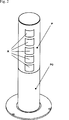
Die
In der
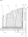
Die
Die
Die
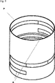
Die
In der
Schließlich zeigt die
Bezugszeichenliste:LIST OF REFERENCE NUMBERS
-
- CC
- MagnetspulensystemMagnet coil system
- HH
- He-InnenrohrHe-inner tube
- H1H1
- He-BehälterHe-container
- SS
- StrahlungsschildinnenrohrRadiation shield inner tube
- S1S1
- Behälter mit flüssigem StickstoffContainer with liquid nitrogen
- S2S2
- StrahlungsschildbehälterRadiation shield container
- PP
- FeldformvorrichtungField shaping device
- P0P0
- Stützrohr, TrägerrohrSupport tube, support tube
- P1P1
- Klemmmechanismusclamping mechanism
- AA
- Aussparungrecess
- AVAV
- Arbeitsvolumenworkload
- RR
- RaumtemperaturinnenrohrRoom temperature inner pipe
- R1R1
- RaumtemperaturbehälterRoom temperature Bottles
- CCCC
- Kryokühlercryocooler
Claims (10)
Priority Applications (5)
| Application Number | Priority Date | Filing Date | Title |
|---|---|---|---|
| DE102015225731.2A DE102015225731B3 (en) | 2015-12-17 | 2015-12-17 | Easily accessible deep-frozen NMR shim arrangement |
| EP16202858.3A EP3182147B1 (en) | 2015-12-17 | 2016-12-08 | Readily accessible deep cooled nmr shim assembly |
| JP2016242402A JP6340403B2 (en) | 2015-12-17 | 2016-12-14 | Easily accessible deep-temperature frozen NMR shim arrangement |
| CN201611163551.5A CN106898452B (en) | 2015-12-17 | 2016-12-16 | The NMR shimming device for the cryogenic refrigeration being easily accessible to |
| US15/381,174 US9766312B2 (en) | 2015-12-17 | 2016-12-16 | Easily accessible deep-frozen NMR shim arrangement |
Applications Claiming Priority (1)
| Application Number | Priority Date | Filing Date | Title |
|---|---|---|---|
| DE102015225731.2A DE102015225731B3 (en) | 2015-12-17 | 2015-12-17 | Easily accessible deep-frozen NMR shim arrangement |
Publications (1)
| Publication Number | Publication Date |
|---|---|
| DE102015225731B3 true DE102015225731B3 (en) | 2017-04-06 |
Family
ID=57539078
Family Applications (1)
| Application Number | Title | Priority Date | Filing Date |
|---|---|---|---|
| DE102015225731.2A Expired - Fee Related DE102015225731B3 (en) | 2015-12-17 | 2015-12-17 | Easily accessible deep-frozen NMR shim arrangement |
Country Status (5)
| Country | Link |
|---|---|
| US (1) | US9766312B2 (en) |
| EP (1) | EP3182147B1 (en) |
| JP (1) | JP6340403B2 (en) |
| CN (1) | CN106898452B (en) |
| DE (1) | DE102015225731B3 (en) |
Cited By (3)
| Publication number | Priority date | Publication date | Assignee | Title |
|---|---|---|---|---|
| DE102019209160B3 (en) * | 2019-06-25 | 2020-10-08 | Bruker Switzerland Ag | Cryostat arrangement with resilient, thermally conductive connecting element |
| DE102022207486B3 (en) | 2022-07-21 | 2023-09-14 | Bruker Switzerland Ag | Passive reduction of temperature-induced shim drift in NMR magnet systems with a regulating element to regulate thermally induced length changes |
| EP4310529A1 (en) | 2022-07-21 | 2024-01-24 | Bruker Switzerland AG | Active reduction of temperature-indexed shim drift in nmr magnetic systems |
Families Citing this family (2)
| Publication number | Priority date | Publication date | Assignee | Title |
|---|---|---|---|---|
| CN108398657B (en) * | 2018-01-12 | 2020-12-29 | 上海东软医疗科技有限公司 | Magnetic resonance transmitting coil |
| DE102020204196B3 (en) | 2020-03-31 | 2021-07-15 | Bruker Switzerland Ag | Shim device with a high-temperature superconducting shim conductor track, magnet arrangement and method for charging an HTS shim device |
Citations (7)
| Publication number | Priority date | Publication date | Assignee | Title |
|---|---|---|---|---|
| DE10104054C1 (en) * | 2001-01-31 | 2002-07-04 | Bruker Ag Faellanden | Magnet device with superconductive magnetic coil system e.g. for magnetic resonance imaging or spectroscopy, includes compensation of magnetic field inhomogeneities |
| DE10116505A1 (en) * | 2001-04-03 | 2002-10-17 | Bruker Biospin Gmbh | Integral passive shim system for a magnetic resonance apparatus |
| JP3737636B2 (en) * | 1998-07-23 | 2006-01-18 | 株式会社神戸製鋼所 | Superconducting magnet device |
| JP4384220B2 (en) * | 2007-11-14 | 2009-12-16 | 株式会社神戸製鋼所 | Superconducting magnet device |
| US7961067B2 (en) * | 2006-07-27 | 2011-06-14 | Hitachi, Ltd. | Superconducting magnet apparatus and magnetic resonance imaging apparatus |
| DE102009045774B4 (en) * | 2008-04-22 | 2012-07-05 | Bruker Biospin Gmbh | A compact superconducting magnet arrangement with active shielding, wherein the shielding coil is used for field shaping |
| DE102012220126A1 (en) * | 2012-11-05 | 2014-05-08 | Bruker Biospin Ag | A magnet assembly comprising a superconducting magnet coil system and a magnetic field shaping apparatus for magnetic resonance spectroscopy |
Family Cites Families (16)
| Publication number | Priority date | Publication date | Assignee | Title |
|---|---|---|---|---|
| DE1016505B (en) | 1954-04-21 | 1957-09-26 | Florencio Bienvenido Casale | Continuously working jet engine, especially for motor vehicle propulsion |
| JPH01246805A (en) * | 1988-03-29 | 1989-10-02 | Toshiba Corp | Superconducting magnet apparatus |
| JPH0438931A (en) * | 1990-06-05 | 1992-02-10 | Hitachi Ltd | Nuclear magnetic resonance apparatus |
| US5389909A (en) * | 1993-11-08 | 1995-02-14 | General Electric Company | Open architecture magnetic resonance imaging passively shimmed superconducting magnet assembly |
| JP3618910B2 (en) * | 1996-07-10 | 2005-02-09 | 三菱電機株式会社 | Magnetic field correction method for electromagnet device |
| US6783059B2 (en) * | 2002-12-23 | 2004-08-31 | General Electric Company | Conduction cooled passively-shielded MRI magnet |
| JP2004259925A (en) * | 2003-02-26 | 2004-09-16 | Jeol Ltd | Conduction cooling type superconductive magnet device for nuclear magnetic resonator |
| JP2006261335A (en) * | 2005-03-16 | 2006-09-28 | Kobe Steel Ltd | Superconducting magnet apparatus |
| US7541812B2 (en) * | 2007-02-13 | 2009-06-02 | Kabushiki Kaisha Toshiba | MRI apparatus, NMR analyzer, and gantry |
| JP5203682B2 (en) * | 2007-02-13 | 2013-06-05 | 株式会社東芝 | MRI apparatus, NMR analyzer, and static magnetic field generator |
| JP5175500B2 (en) * | 2007-04-17 | 2013-04-03 | 独立行政法人物質・材料研究機構 | Superconducting magnet device |
| JP4402707B2 (en) * | 2007-07-06 | 2010-01-20 | 三菱電機株式会社 | Shim support guide jig for magnetic field generator |
| CN102136337B (en) * | 2010-12-08 | 2012-03-28 | 中国科学院电工研究所 | Highfield high uniformity nuclear magnetic resonance superconducting magnet system |
| US9322892B2 (en) * | 2011-12-20 | 2016-04-26 | General Electric Company | System for magnetic field distortion compensation and method of making same |
| US9274188B2 (en) * | 2012-11-30 | 2016-03-01 | General Electric Company | System and apparatus for compensating for magnetic field distortion in an MRI system |
| CN105097179A (en) * | 2014-05-07 | 2015-11-25 | 中国科学院高能物理研究所 | Superconducting magnet apparatus capable of providing high-intensity magnetic fields and high magnetic field gradients |
-
2015
- 2015-12-17 DE DE102015225731.2A patent/DE102015225731B3/en not_active Expired - Fee Related
-
2016
- 2016-12-08 EP EP16202858.3A patent/EP3182147B1/en active Active
- 2016-12-14 JP JP2016242402A patent/JP6340403B2/en active Active
- 2016-12-16 CN CN201611163551.5A patent/CN106898452B/en active Active
- 2016-12-16 US US15/381,174 patent/US9766312B2/en active Active
Patent Citations (8)
| Publication number | Priority date | Publication date | Assignee | Title |
|---|---|---|---|---|
| JP3737636B2 (en) * | 1998-07-23 | 2006-01-18 | 株式会社神戸製鋼所 | Superconducting magnet device |
| DE10104054C1 (en) * | 2001-01-31 | 2002-07-04 | Bruker Ag Faellanden | Magnet device with superconductive magnetic coil system e.g. for magnetic resonance imaging or spectroscopy, includes compensation of magnetic field inhomogeneities |
| US6617853B2 (en) * | 2001-01-31 | 2003-09-09 | Bruker Biospin Ag | Magnet arrangement comprising a superconducting magnet coil system and a magnetic field shaping device for high-resolution magnetic resonance spectroscopy |
| DE10116505A1 (en) * | 2001-04-03 | 2002-10-17 | Bruker Biospin Gmbh | Integral passive shim system for a magnetic resonance apparatus |
| US7961067B2 (en) * | 2006-07-27 | 2011-06-14 | Hitachi, Ltd. | Superconducting magnet apparatus and magnetic resonance imaging apparatus |
| JP4384220B2 (en) * | 2007-11-14 | 2009-12-16 | 株式会社神戸製鋼所 | Superconducting magnet device |
| DE102009045774B4 (en) * | 2008-04-22 | 2012-07-05 | Bruker Biospin Gmbh | A compact superconducting magnet arrangement with active shielding, wherein the shielding coil is used for field shaping |
| DE102012220126A1 (en) * | 2012-11-05 | 2014-05-08 | Bruker Biospin Ag | A magnet assembly comprising a superconducting magnet coil system and a magnetic field shaping apparatus for magnetic resonance spectroscopy |
Cited By (5)
| Publication number | Priority date | Publication date | Assignee | Title |
|---|---|---|---|---|
| DE102019209160B3 (en) * | 2019-06-25 | 2020-10-08 | Bruker Switzerland Ag | Cryostat arrangement with resilient, thermally conductive connecting element |
| DE102022207486B3 (en) | 2022-07-21 | 2023-09-14 | Bruker Switzerland Ag | Passive reduction of temperature-induced shim drift in NMR magnet systems with a regulating element to regulate thermally induced length changes |
| EP4310529A1 (en) | 2022-07-21 | 2024-01-24 | Bruker Switzerland AG | Active reduction of temperature-indexed shim drift in nmr magnetic systems |
| EP4310528A1 (en) | 2022-07-21 | 2024-01-24 | Bruker Switzerland AG | Passive reduction of temperature-induced shim drift in nmr magnetic systems |
| DE102022207489A1 (en) | 2022-07-21 | 2024-02-01 | Bruker Switzerland Ag | Active reduction of temperature-induced shim drift in NMR magnetic systems |
Also Published As
| Publication number | Publication date |
|---|---|
| CN106898452A (en) | 2017-06-27 |
| CN106898452B (en) | 2019-09-24 |
| JP6340403B2 (en) | 2018-06-06 |
| US20170176554A1 (en) | 2017-06-22 |
| EP3182147A1 (en) | 2017-06-21 |
| EP3182147B1 (en) | 2018-03-28 |
| JP2017142231A (en) | 2017-08-17 |
| US9766312B2 (en) | 2017-09-19 |
Similar Documents
| Publication | Publication Date | Title |
|---|---|---|
| EP3182147B1 (en) | Readily accessible deep cooled nmr shim assembly | |
| DE102005028414B4 (en) | Device for generating a pulsed magnetic field | |
| DE3245945C2 (en) | ||
| DE102009045774B4 (en) | A compact superconducting magnet arrangement with active shielding, wherein the shielding coil is used for field shaping | |
| DE69532220T2 (en) | Disc-shaped magnet for magnetic resonance imaging | |
| EP0317853B1 (en) | Magnet assembly for a nuclear spin tomography apparatus with superconducting main-field coils and normally conducting gradient coils | |
| DE102005044635B4 (en) | Device for magnetic field generation and magnetic resonance system | |
| DE102019209160B3 (en) | Cryostat arrangement with resilient, thermally conductive connecting element | |
| EP0116364A1 (en) | Cooling device for a low temperature magnetic system | |
| DE19947539B4 (en) | Gradient coil arrangement with damping of internal mechanical vibrations | |
| EP0293723A2 (en) | Magnetic coil system of an NMR imaging system, with superconducting coils and a shield for protection against eddy currents | |
| EP3614162B1 (en) | Permanently magnetized arrangement for producing a homogeneous field (3d halbach) | |
| DE102013219453B3 (en) | Dynamic nuclear polarization-device for producing hyperpolarized liquid for nuclear magnetic resonance- and magnetic resonance imaging-measurements, has cryostat which has opening and load path for loading cryostat with measuring sample | |
| DE3900725C2 (en) | ||
| EP1564562B1 (en) | Hybrid magnet assembly | |
| DE102009004899B4 (en) | Superconducting actively shielded magnet | |
| EP3242141B1 (en) | Magnetic and cryostatic device and method for passive shimming | |
| DE102009045373A1 (en) | A compact superconducting magnet arrangement with active shielding, wherein the shielding coil attenuates the field maximum of the main field coil | |
| EP1229340B1 (en) | Magnet assembly with a superconducting magnet coil system and a magnetic field forming device for high resolution magnetic resonance spectroscopy | |
| EP3336568B1 (en) | Magnet assembly with superconducting closed hts shims | |
| DE102004023072B4 (en) | Magnet system with shielded regenerator material and method of operation of the magnet system | |
| DE102012220126A1 (en) | A magnet assembly comprising a superconducting magnet coil system and a magnetic field shaping apparatus for magnetic resonance spectroscopy | |
| DE102022207486B3 (en) | Passive reduction of temperature-induced shim drift in NMR magnet systems with a regulating element to regulate thermally induced length changes | |
| DE3714017A1 (en) | MAGNETIC SYSTEM OF A SYSTEM FOR NUCLEAR SPIN TOMOGRAPHY WITH SUPRAL-CONDUCTING INDIVIDUAL COILS AND A REFRIGERATOR PLATE | |
| DE102012106211A1 (en) | Superconducting magnet arrangement |
Legal Events
| Date | Code | Title | Description |
|---|---|---|---|
| R012 | Request for examination validly filed | ||
| R079 | Amendment of ipc main class |
Free format text: PREVIOUS MAIN CLASS: G01R0033300000 Ipc: G01R0033387500 |
|
| R016 | Response to examination communication | ||
| R018 | Grant decision by examination section/examining division | ||
| R020 | Patent grant now final | ||
| R119 | Application deemed withdrawn, or ip right lapsed, due to non-payment of renewal fee |