EP0111200A1 - Fuel injection timing control system - Google Patents
Fuel injection timing control system Download PDFInfo
- Publication number
- EP0111200A1 EP0111200A1 EP83111617A EP83111617A EP0111200A1 EP 0111200 A1 EP0111200 A1 EP 0111200A1 EP 83111617 A EP83111617 A EP 83111617A EP 83111617 A EP83111617 A EP 83111617A EP 0111200 A1 EP0111200 A1 EP 0111200A1
- Authority
- EP
- European Patent Office
- Prior art keywords
- fuel injection
- fuel
- valve
- internal combustion
- combustion engine
- Prior art date
- Legal status (The legal status is an assumption and is not a legal conclusion. Google has not performed a legal analysis and makes no representation as to the accuracy of the status listed.)
- Granted
Links
Images


Classifications
-
- F—MECHANICAL ENGINEERING; LIGHTING; HEATING; WEAPONS; BLASTING
- F02—COMBUSTION ENGINES; HOT-GAS OR COMBUSTION-PRODUCT ENGINE PLANTS
- F02D—CONTROLLING COMBUSTION ENGINES
- F02D41/00—Electrical control of supply of combustible mixture or its constituents
- F02D41/30—Controlling fuel injection
- F02D41/38—Controlling fuel injection of the high pressure type
- F02D41/40—Controlling fuel injection of the high pressure type with means for controlling injection timing or duration
- F02D41/401—Controlling injection timing
-
- F—MECHANICAL ENGINEERING; LIGHTING; HEATING; WEAPONS; BLASTING
- F02—COMBUSTION ENGINES; HOT-GAS OR COMBUSTION-PRODUCT ENGINE PLANTS
- F02M—SUPPLYING COMBUSTION ENGINES IN GENERAL WITH COMBUSTIBLE MIXTURES OR CONSTITUENTS THEREOF
- F02M59/00—Pumps specially adapted for fuel-injection and not provided for in groups F02M39/00 -F02M57/00, e.g. rotary cylinder-block type of pumps
- F02M59/20—Varying fuel delivery in quantity or timing
- F02M59/36—Varying fuel delivery in quantity or timing by variably-timed valves controlling fuel passages to pumping elements or overflow passages
- F02M59/365—Varying fuel delivery in quantity or timing by variably-timed valves controlling fuel passages to pumping elements or overflow passages valves being actuated by the fluid pressure produced in an auxiliary pump, e.g. pumps with differential pistons; Regulated pressure of supply pump actuating a metering valve, e.g. a sleeve surrounding the pump piston
-
- F—MECHANICAL ENGINEERING; LIGHTING; HEATING; WEAPONS; BLASTING
- F02—COMBUSTION ENGINES; HOT-GAS OR COMBUSTION-PRODUCT ENGINE PLANTS
- F02M—SUPPLYING COMBUSTION ENGINES IN GENERAL WITH COMBUSTIBLE MIXTURES OR CONSTITUENTS THEREOF
- F02M63/00—Other fuel-injection apparatus having pertinent characteristics not provided for in groups F02M39/00 - F02M57/00 or F02M67/00; Details, component parts, or accessories of fuel-injection apparatus, not provided for in, or of interest apart from, the apparatus of groups F02M39/00 - F02M61/00 or F02M67/00; Combination of fuel pump with other devices, e.g. lubricating oil pump
- F02M63/02—Fuel-injection apparatus having several injectors fed by a common pumping element, or having several pumping elements feeding a common injector; Fuel-injection apparatus having provisions for cutting-out pumps, pumping elements, or injectors; Fuel-injection apparatus having provisions for variably interconnecting pumping elements and injectors alternatively
- F02M63/0205—Fuel-injection apparatus having several injectors fed by a common pumping element, or having several pumping elements feeding a common injector; Fuel-injection apparatus having provisions for cutting-out pumps, pumping elements, or injectors; Fuel-injection apparatus having provisions for variably interconnecting pumping elements and injectors alternatively for cutting-out pumps or injectors in case of abnormal operation of the engine or the injection apparatus, e.g. over-speed, break-down of fuel pumps or injectors ; for cutting-out pumps for stopping the engine
- F02M63/0215—Fuel-injection apparatus having several injectors fed by a common pumping element, or having several pumping elements feeding a common injector; Fuel-injection apparatus having provisions for cutting-out pumps, pumping elements, or injectors; Fuel-injection apparatus having provisions for variably interconnecting pumping elements and injectors alternatively for cutting-out pumps or injectors in case of abnormal operation of the engine or the injection apparatus, e.g. over-speed, break-down of fuel pumps or injectors ; for cutting-out pumps for stopping the engine by draining or closing fuel conduits
-
- F—MECHANICAL ENGINEERING; LIGHTING; HEATING; WEAPONS; BLASTING
- F02—COMBUSTION ENGINES; HOT-GAS OR COMBUSTION-PRODUCT ENGINE PLANTS
- F02B—INTERNAL-COMBUSTION PISTON ENGINES; COMBUSTION ENGINES IN GENERAL
- F02B3/00—Engines characterised by air compression and subsequent fuel addition
- F02B3/06—Engines characterised by air compression and subsequent fuel addition with compression ignition
-
- F—MECHANICAL ENGINEERING; LIGHTING; HEATING; WEAPONS; BLASTING
- F02—COMBUSTION ENGINES; HOT-GAS OR COMBUSTION-PRODUCT ENGINE PLANTS
- F02D—CONTROLLING COMBUSTION ENGINES
- F02D41/00—Electrical control of supply of combustible mixture or its constituents
- F02D41/22—Safety or indicating devices for abnormal conditions
- F02D2041/224—Diagnosis of the fuel system
- F02D2041/226—Fail safe control for fuel injection pump
-
- F—MECHANICAL ENGINEERING; LIGHTING; HEATING; WEAPONS; BLASTING
- F02—COMBUSTION ENGINES; HOT-GAS OR COMBUSTION-PRODUCT ENGINE PLANTS
- F02D—CONTROLLING COMBUSTION ENGINES
- F02D2200/00—Input parameters for engine control
- F02D2200/02—Input parameters for engine control the parameters being related to the engine
- F02D2200/06—Fuel or fuel supply system parameters
- F02D2200/0602—Fuel pressure
-
- F—MECHANICAL ENGINEERING; LIGHTING; HEATING; WEAPONS; BLASTING
- F02—COMBUSTION ENGINES; HOT-GAS OR COMBUSTION-PRODUCT ENGINE PLANTS
- F02D—CONTROLLING COMBUSTION ENGINES
- F02D41/00—Electrical control of supply of combustible mixture or its constituents
- F02D41/30—Controlling fuel injection
- F02D41/38—Controlling fuel injection of the high pressure type
- F02D41/40—Controlling fuel injection of the high pressure type with means for controlling injection timing or duration
- F02D41/406—Electrically controlling a diesel injection pump
- F02D41/407—Electrically controlling a diesel injection pump of the in-line type
-
- Y—GENERAL TAGGING OF NEW TECHNOLOGICAL DEVELOPMENTS; GENERAL TAGGING OF CROSS-SECTIONAL TECHNOLOGIES SPANNING OVER SEVERAL SECTIONS OF THE IPC; TECHNICAL SUBJECTS COVERED BY FORMER USPC CROSS-REFERENCE ART COLLECTIONS [XRACs] AND DIGESTS
- Y02—TECHNOLOGIES OR APPLICATIONS FOR MITIGATION OR ADAPTATION AGAINST CLIMATE CHANGE
- Y02T—CLIMATE CHANGE MITIGATION TECHNOLOGIES RELATED TO TRANSPORTATION
- Y02T10/00—Road transport of goods or passengers
- Y02T10/10—Internal combustion engine [ICE] based vehicles
- Y02T10/40—Engine management systems
Definitions
- This invention relates to a fuel control system of an internal combustion engine capable of readily adjusting the period and time of fuel injection without interrupting the operation of the internal combustion engine.
- a fuel injection pump of a constant stroke type operative to compress a liquid fuel sealed between a plunger and a barrel and raise its pressure by lifting the plunger by means of a cam linked thereto and a fuel valve automatically effecting fuel injection as it is loaded with a liquid fuel under high pressure are connected together through a fuel injection pipe.
- the fuel injection time is exclusively decided by the profile of the driving cam.
- it has hitherto been usual practice to attain the end by modifying the position in which the cam is mounted on a cam shaft. This practice has made it necessary to interrupt the normal operation of the internal combustion engine.
- F ig. 1 shows one type of fuel injection system of an internal combustion engine of the prior art in which a fuel injection pump 17 of a constant stroke type is connected to a closed nozzle type fuel valve 11 through a fuel injection pipe 7.
- a cam 14 mounted on a cam shaft 18 rotating in synchronism with the engine crank shaft causes plunger 1 to move in vertical reciprocatory movement in a barrel 19. That is, a roller 15 is moved upwardly as the cam 14 rotates, to thereby move the plunger 1 in vertical reciprocatory movement.
- a liquid fuel is fed through a fuel suction pipe 6 into a suction chamber 20, from which the fuel flows through a suction port 24 formed in a wall of a cylinder 16 into a pressure chamber 21 in an upper portion of the plunger 1 when the plunger moves downwardly.
- the liquid fuel within the pressure chamber 21 is compressed and has its pressure raised as the suction port 24 is closed by an upper end of the plunger 1, to move a discharge valve body 4 upwardly against the biasing force of a spring 5. This permits the liquid fuel to flow through a fuel injection pipe 7 into a pressure accumulating chamber 22 of the fuel valve 11.
- the pressure of the liquid fuel within the pressure accumulating chamber 22 overcomes the biasing force of spring 13, then needle valve 11 is lifted and the liquid fuel is injected through a nozzle 12 into a cylinder not shown.
- the injection of the fuel into the cylinder terminates when an oblique cutout 2 formed at one side of the plunger 1 is brought into communication with a fuel discharge port 25 and the liquid fuel in the pressure chamber 21 is discharged through a vertical groove 3 into the suction chamber 20.
- the volume of the fuel injected into the internal combustion engine during one stroke of the plunger may vary depending on the position of the oblique cutout 2 and may be decided by the rotational angle of the plunger 1.
- the rotational angle of the plunger 1 may be varied by means of a governor 9 through a rack 8.
- the cam 14 is mounted on the cam shaft 18 in a manner to have an advance angle.
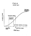
- Fig. 2 is a graph showing the relation between the crank angle 8 and the stroke h of the plunger 1.
- injection begins at a point A and thereafter the piston reaches the top dead center.
- This section corresponds to an advanced angle a which is about 17 degrees in a four-stroke internal combustion engine of a large size.
- the upward stroke of the plunger 1 continues after termination of the fuel injection, and then the plunger 1 shifts to a downward stroke.
- the advance angle a greatly influences the operation performance of the internal combustion engine, particularly its fuel consumption rate, and the optimum value of advanced angle a may greatly vary depending on the operation conditions of the internal combustion engine or on the quality of the liquid fuel.
- the liquid fuel used shows a change in quality or when the internal combustion engine is one for driving a generator which shows often changes in load, it would be impossible to operate the internal combustion engine at an optimum fuel consumption rate by using the fuel injection system of the prior art shown in Fig. 1.
- an oil discharge valve having a valve body which is mechanically linked to the plunger and may be controlled from outside by a position control signal, is mounted between the upper pressure chamber 21 of the fuel injection pump and the suction chamber 20 thereof.
- a fuel control valve is provided, which is mounted between the fuel injection pump and the fuel injection valve and driven by a cam having advancing angle, to thereby enable the fuel injection time to be altered.
- the invention has been developed for the purpose of solving the aforesaid technical problems of the prior art. Accordingly, the invention has as one of its objects the provision of a fuel injection timing control system of an internal combustion engine capable of altering as desired the fuel injection time or the advance angle during the operation of the internal combustion engine, to thereby enable the internal combustion engine to operate at an optimum fuel consumption rate.
- Another object is to provide a fuel injection timing control system of an internal combustion engine which can be incorporated in an internal combustion engine already in use.
- a still another object is to provide a fuel injection timing control system of an internal combustion engine enabling operation of the internal combustion engine to be continued without interruption of engine operation when some trouble occurs in the fuel injection timing control system.
- Fig. 3 is a schematic view of a first embodiment in which the position of the cam 14 is set beforehand to provide a maximum advance angle in the actual operation range of internal combustion engines.
- the advance angle is selected greater by 5-8 degrees as compared with the advance angle adopted in conventional fuel injection devices, and the value may vary depending on the type of the combustion engine.
- Formed at one side of an upper portion of barrel 19 of the fuel injection pump 17 is a spill port 51 opening at a top end of the pressure chamber 21 and maintained in communication with an inlet port 53 of an oil discharge valve 30 through a connecting pipe 39.
- Formed at a side of a central portion of the barrel 19 a fuel discharge port 52 which is maintained in communication with an outlet port 54 of the fuel discharge valve 30 through a fuel discharge pipe 40.
- the oil discharge valve 30 includes a barrel 41, a control piston 42 contained in the barrel 41 and a closing needle 43 also contained in the barrel 41 and disposed above the control piston 42.
- the control piston 42 and closing needle 43 which can move in sliding movements in the barrel 41 are designed so that their crosssectional areas have the ratio of about 4:1 to increase force by about fourfold.
- Threadably connected to a bottom wall of the barrel 41 is a plug 56 which cooperates with the control piston 42 to define therebetween a control chamber 44.
- a control port 57 opening in the control chamber 44 is formed at a side of a lower portion of the barrel 41, while a drain port 55 is formed at a side of its central portion to release the oil which is collected at an upper end of the control piston 42 or a lower end of the closing needle 43.
- the inlet port 53 and outlet port 54 are maintained in communication with each other through a communicating chamber 45 inside the barrel 41. However, when the closing needle 43 moves to its uppermost position, the inlet port 53 near the communicating chamber 45 provides a seat for the closing needle 43, so that the closing needle 43 blocks communication between the inlet port 53 and communicating chamber 45 or outlet port 54.
- the control port 57 of the oil discharge valve 30 is connected through a fluid pressure pipe 38 to an outlet port 58 of a solenoid-operated valve 31 which is formed with a pressure port 59 and a drain port 60 besides the outlet port 58.
- An electric signal supplied to the solenold-operated valve 31 moves a spool built therein to selectively connect the outlet port 58 to the pressure port 59 or drain port 60. More specifically, when an electric signal is supplied to solenoid 61 of the solenoid-operated valve 31, the spool, not shown, is driven to move against the biasing force of a spring 63, to bring the pressure port 59 into communication with the outlet port 58. When the electric signal is removed, the spool is restored to its original position by the biasing force of the spring 63 and closes the pressure port 59, to bring the outlet port 58 into communication with the drain port 60.
- the solenoid-operated valve 31 of the aforesaid construction is referred to as a single solenoid spring return type.
- the invention is not limited to the aforesaid specific type of solenoid-operated valve and other type of solenoid-operated valve may be used.
- switching of the solenoid-operated valve can be controlled by supplying an electric signal to either one of the two solenoids.
- the solenoid-operated valve of this construction the number of a solenoid drive circuit and wires for providing connections would be doubled as compared with the use of the solenoid-operated valve of the single solenoid spring return type.
- the former can be expected to effect switching at higher speed than the latter.
- a servo valve of an electrohydraulic type may be used. This type of servo valve can effect switching at high speed, although it is expensive.
- a high pressure hydraulic pump 32 raises the pressure of a working fluid in a reservoir 33 to supply the working fluid under high pressure to the pressure port 59 of the solenoid-operated valve 31 through a distributing pipe 49.
- the high pressure hydraulic pump 32 is a source of high pressure fluid.
- branch pipes supply the high pressure fluid from the distributing pipe 49 to pressure ports of respective solenoid valve of cylinders.
- the reservoir 33 which functions as a.source of low pressure fluid is connected to the drain port 60 of the solenoid-operated valve 31 through a return pipe 50.
- the distributing pipe 49 has a pressure adjusting valve 62 mounted therein to keep constant the high pressure of the fluid.
- an accumulator may be mounted in the distributing pipe 49 to minimize fluctuations in the pressure of the high pressure fluid.
- a hydraulic pump of the kind which would not case excessively high pressure in the distributing pipe 49 , such as a velocity type high pressure hydraulic pump.
- a resolver 35 is mounted on the cam shaft 18 by a fixture, not shown, for rotation therewith as a unit, to perform the function of detecting the rotational angle of the cam shaft 18 or a crank angle.
- the invention is not limited to the specific form of the resolver 35 but any known means, such as a synchronizer, a shaft encoder or a potentiometer, for example, may be used for detecting the rotational angle of the cam shaft 18.
- the resolver 35 is connected through a wire 36 to a control box 34 for transmitting an angle information thereto.
- the control box 34 includes a setter 46 and an indicator 48 contained therein, and is connected to the solenoid-operated valve 31 through a wire 37 to supply an electric signal thereto.
- the setter 46 which may comprise a digital switch of a decimal system has the function of setting an advance angle a or a crank angle for supplying an electric signal.
- the setter 46 is of the same number as the cylinder of the engine.
- the control box 34 is shown as being used with the engine of four cylinders.
- the indicator 48 has the function of indicating the crank angle and engine speed and may be in the form of a light emitting diode of a decimal system, for example.
- a cut-off valve 29 may be mounted in the. connecting pipe 39.
- abnormality detecting means A which monitors the manner of injection of the liquid fuel to detect any abnormality in the injected fuel, may be used.
- the abnormality detecting means A When the abnormality detecting means A is used, for a example, a pressure sensor B is mounted in the fuel injection pipe 7, and a monitor circuit C is used for monitoring the injection pressure of the fuel and supplying an output signal to the abnormality detecting means A.
- the abnormality detecting means A operates so that by the fact that the one occurrence of fuel injection during one complete revolution of the cam 14 during engine operation, it checks the occurrence of the pressure wave of the fuel and determines that some abnormality exists in case no pressure wave is sensed during more than one rotation of the engine over a certain load (30% load, example). When this situation prevails, the abnormality detecting means A renders the cut-off valve 29 operative through a drive circuit D.
- Failure detecting means E for detecting the failure of an electrical device for driving the oil discharge valve 30 may be separately mounted for rendering the cut-off valve 29 operative by its output.
- the movement of a valve body 42 of the oil discharge valve 30 may be detected by a position detector F and monitored by a monitor circuit G.
- a differential transformer or a limit switch may be used as the position detector F, for example.
- the failure detecting means E checks the cycle of signals from the position detector F and the cycle of signals from the pressure sensor B to determine the presence of a failure and supplies a signal to the drive circuit D to render the cut-off valve 29 operative.
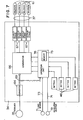
- Fig. 4 is a block diagram of one constructional form of control box 34.
- the resolver 35 produces an angle signal which is changed to a binary digital angle signal by a converter 64 and input to a comparator 66. Meanwhile a decimal advance angle a set in the setter 46 is changed to a binary digital signal by a converter 70 and input to the comparator 66.
- the two types of signal described hereinabove are compared with each other in the comparator 66 which, when the actual crank angle reach the set value, supplies to an output stage 67 a pulse signal of a predetermined duration which is amplified and energizes the solenoid 61 of the solenoid-operated valve 31.
- the duration of the pulse signal would have only to be greater in value than'a maximum value of the fuel injection period and may vary depending on the size and type of the internal bomustion engine. In a marine engine of a large size, about 90 degrees would be enough, for example.
- a frequency to voltage converter 68 receives binary digital signal of angle and converts to engine speed.
- the indicator 48 indicates the engine speed and the crank angle.
- the advance angle of an optimum value is set in the setter 46.
- the optimum value of the advance angle a is substantially decided in test run of engine so as to minimize the fuel consumption rate according to each engine speed and the load applied thereto.
- Value a can be modified according to specific features of each cylinder and the environment in which the engine operates. Stated differently, the optimum value obtained in the test run is modified so that maximum values of the exhaust gas temperature and combustion pressure will not exceed the design limit value.
- the position in which the cam 14 is mounted on the cam shaft 18 is selected to have an angle slightly larger (by about 3 degrees,.for example) than the maximum value of the optimum advance angle a obtained in the test run, so that the position of the cam 14 can be modified in conformity with changes in environment, such as air temperature and cooling water temperature, and aging effect.
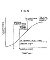
- Fig. 5 is a graph showing the relation between the rotational angle (crank angle 8) of engine and the stroke h of the plunger 1. This relation will be described by referring to Figs. 3 and 5.
- the crank angle 6 detected by the resolver 35 does not reach the advance angle a set in the setter 46 of the control box 34 (point A in Fig. 5), so that the solenoid 61 of the solenoid-operated valve 31 remains de energized and the outlet port 58 is communicated with the drain port 60.
- the control port 57 of the oil discharge valve 30 is maintained in communication with the reservoir 33 which is a low pressure fluid source through the pressure fluid pipe 38, solenoid-operated valve 31 and return pipe 50, so that the control chamber 44 is kept at an atmospheric pressure level.
- the liquid fuel sent to the fuel injection pump 17 through the fuel suction pipe 6 is filled in the pressure chamber 21.
- the liquid fuel which is slightly pressurized while being fed through the suction pipe 6 acts on a top end of the closing needle 43 as it flows from the suction chamber 20 into the communicating chamber 45 of the oil discharge valve 30, to force the closing needle 43 and hence the control piston 42 to move downwardly and bring the inlet port 53 and outlet port 54 of the oil discharge valve 30 into communication with each other.
- the top end of the closing needle 43 brings the inlet port 53 and outlet port 54 out of communication with each other, thereby blocking the flow of the fuel from the inlet port 53 to the suction chamber 20.
- the needle valve body 10 is lifted, to supply the fuel by injection into the cylinder, not shown, through the nozzle 12.
- the fuel injection pressure is as high as about 1000 atg (kg/cm 2 G).
- suitable values should be selected for the pressure of the high pressure fluid fource and for the cross-sectional areas of the control piston 42 and inlet port 53. For example, assume that the following values are selected. Then, the allowable maximum pressure of the liquid fuel is as follows:
- the plunger 1 continues its upward movement even after the injection is terminated and begins to move downwardly after passing by the top dead point.
- the cam 14 further continues its rotation, and the solenoid 61 of the solenoid-operated valve 31 is deenergized as the electric signal supplied from the control box 34 is interrupted, to thereby bring the ports of the solenoid-operated valve 31 to their original positions by the biasing force of the spring 63. That is, the pressure port 59 is closed and the outlet port 58 is connected to the drain port 60.
- This causes the fuel in the control chamber 44 of the oil discharge valve 30 to flow to the reservoir 33 through the solenoid-operated valve 31, thereby causing the pressure of the fuel in the control chamber 44 to drop to an atmospheric pressure level.
- This moves the closing needle 43 to move downwardly, so that the pressure chamber 21 and suction chamber 20 of the fuel injection pump 17 are brought into communication with each other through the oil discharge valve 30.
- the angular width is about 50 degrees by crank angle typically. So the electric signal supplied from the control box 34 has enough pulse duration corresponding to about 90 degrees.
- the feature of the invention is that the cam is set at its maximum advanced angle before the operation of the engine and the fuel compressed by plunger 1 is returned to the suction side of the fuel injection pump in a volume corresponding to a reduction in the advance angle a, and adjust the initiation of the operation of the plunger to inject the fuel, to thereby fluidly effect adjustments of the advance angle a.
- the aforementioned suction side of the fuel injection pump is not restricted to the suction chamber of the fuel injection pump, but it may be a tank for supplying the liquid fuel or a sump (which is communicated with the reservoir) for collecting the spilled fuel.
- Fig. 6 shows the fuel injection timing control system comprising another embodiment.
- the fuel discharge valve 30 includes a valve body 77 slidably inserted in the barrel 41 which is formed at one side with the inlet port 53 and outlet port 54 capable of being maintained in communication with each other through a control groove 82 formed in the valve body 77.
- the inlet port 53 and outlet port 54 are maintained with the pressure chamber 21 and suction chamber 20 of the fuel injection pump 17 through the communicating pipe 39 and fuel discharge pipe 40 respectively.
- a spring 78 for biasing the valve body 77 upwardly is mounted on a bottom wall of the barrel 41 which has a stopper 79 threadably connected thereto to restrict the downward movement of the valve body 77.
- the valve body 77 has a control edge 81 located at a lower end of the control groove 82 for opening and closing the inlet port 53.
- the valve body 77 also has an edge 80 at an upper end of the control groove 92 which is restricted by the stopper 79 and prevented from closing the outlet port 54 by an edge 80, so that the outlet port 54 is maintained in communication with the control groove 82 at all times.
- the inlet port 53 is closed by the control edge 81 of the valve body 77.
- the control edge 81 opens the inlet port 53 to bring same into communication with the control groove 82.
- the control port 57 is formed at an upper portion of the barrel 41 and maintained in communication with the control chamber 44 restricted between an upper end of the valve body 77 and a top wall of the barrel 41 while being connected to the outlet port 58 of the solenoid-operated valve 31 through the pressure fluid pipe 38.
- Formed at a lower portion of the valve body 77 is an air port 83 which allows the interior of the barrel to be maintained at an atmospheric pressure.
- other parts of the system are similar to those of the embodiment shown in Fig. 3, so that their description will be omitted.
- Fig. 6 the cam 14 is shown in a position in which it does not moves the plunger 1 upwardly.
- the solenoid 61 of the solenoid-operated valve 31 is energized by an electrical signal from the control box 34 to keep the outlet port 58 in communication with the pressure port 59.
- This allows the working fluid to be supplied from the high pressure hydraulic pump 32 to the control chamber 44 of the oil discharge valve 30, to move the valve body 77 against the biasing force of the spring 78 to its lowest position which is determined by the stopper 79.
- the control edge 81 opens the inlet port 53 to bring the pressure chamber 21 and suction chamber 20 of the fuel injection pump 17 into communication with each other through the control groove 82 of the oil discharge valve 30.
- an electric signal is fed again from the control box 34 to energize the solenoid 61 of the solenoid-operated valve 31, to allow the working fluid to flow from the high pressure hydraulic pump 32 to the control chamber 44 of the oil discharge valve 30.
- the valve body 77 is moved downwardly to the position in which it abuts against the stopper 79 as it did before the operation was started.
- the feature of the embodiment shown in Fig. 6 is that in the event that the control box 34 or high pressure hydraulic pump 32 their function, it is impossible tb control the injection at its best timing, but fuel injection can be continued with the timing set for the cam. Thus operation of the internal combustion engine can be continued without interruption. This feature would be particularly important when the internal combustion engine is for marine use, because the vessel can continue navigation under its own power.
- Fig. 7 shows another constructional form of control box 34 according to the invention which is distinguished from the constructional form of control box 34 shown in Fig. 4 in that a load sensor 71 and an rpm. sensor 72 are mounted therein and the frequency to voltage converter 68 is replaced by an operation unit 76.
- the load sensor 71 may be in the form of a rack position detector utilizing a differential transformer.
- other means including a thermometer for measuring the temperature of the exhaust gases, a manometer for measuring the pressure of the air intake and a shaft torque meter for directly measuring the torque may be used instead.
- a tachometer which generates voltage proportional to the rotational speed is usually used as the rpm. sensor 72.
- the rpm. sensor 72 can be dispensed with if a calculation for rpm. is done by the operation unit 76 based on an output of the angle converter 64.
- the control box 34 shown in Fig. 7 will be described mainly by referring to the operation unit 76 which is in the form of a microcomputer, for example.
- a load signal 73 and an rpm. signal 74 are read into the operation unit 76 from the load sensor 71 and rpm. sensor 72, respectively, through an analog-to-digital converter, not shown.
- the operation unit 76 comprises a memory 75 which stores therein, in addition to a program, a series of.optimum advance angles a determined in the test run of the engine according to each engine speed, and load.
- the operation unit 76 reads out an optimum advance angle a (which is referred to as a master signal) from the memory 75 in accordance with the load signal 73 and rpm. signal 74 input thereto.
- the operation unit 76 After adding to or reducing from the master signal a setting signal prepared in the setter 46 which is the switches to compensate for variations in conditions, the operation unit 76 sends the adjusted master signal to the comparator 66.
- the engine shown in F ig. 7 is four cylinder engine. However, the invention is not limited to this specific number of cylinders, but the number of the cylinders may be greater or smaller than four.
- the precision with which control of the advance angle a is effected might be affected by the rpm. of the internal combustion engine.
- the control precision can be improved by compensating for a lag in the operation of the solenoid-operated valve 31 and oil discharge valve 30 in accordance with the rpm. More specifically, the following compensating angle only has to be deducted from the result of the calculation.
- the calculation for correction can be eliminated, thereby simplifying the calculation in the operation-unit 76.
- the control box 34 shown in Fig. 7 has the feature that the advance angle a is automatically selected. More specifically, the optimum values of the advance angle a obtained beforehand and stored in the memory, and a suitable optimum value is read out of the memory in accordance with the rpm. and the load sensed by the respective sensors. In the case of a marine engine, the load is substantially proportional to the third power of the rpm. Thus the advance angle a may be obtained by using the rpm. alone, to thereby dispense with the load sensor 71.
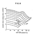
- Fig. 8 shows one example of such processes.
- the abscissa represents in percent the rack displacement 6 indicating a load applied to the internal combustion engine
- the ordinate indicates in degree the advance angle a, with a parameter of the rpm, indicated in percent.
- the points represented by 0 in the diagram are stored in the memory 75 as typical points master signal, and calculation is done by interpolation on the typical points to obtain a desired advance angle a. The calculation may be done as follows:
- the pressure of the fuel in the pressure chamber of the fuel injection pump drops and the injection is terminated when the electric signal fed from the control box is early interrupted by reducing the duration of the pulse of the signal. Therefore, by effecting adjustments of the duration of the pulse of the electric signal, it is possible to define upper limit of the volume of the injected fuel, to thereby enable the system concurrently to serve as a torque limiter which has effect in protecting the internal combustion engine from over torque. Moreover, by increasing or decreasing the pulse duration of the electric signal in conjunction with the target value of the rpm. of the engine, it is possible to effect adjustments of the volume of the injected fuel.
- the governor 9 can be dispensed with, if the oil discharge valve 30 is controlled in this way.
- the oil discharge valve 30 may be eliminated and the solenoid-operated valve 31 may be directly connected to the fuel injection pump 17. This would eliminate a lag in the operation of the oil discharge valve and improve the response of the system. However, it would be necessary to use a solenoid-operative valve of high power capable of withstanding the pressure under which fuel injection is carried out.
- optimum advance angles determined beforehand are set in a setter of a control circuit and a desired optimum value in conformity with prevailing rpm. of the engine and the load applied thereto is taken out during operation, thereby enabling the internal combustion engine to operate at an optimum fuel consumption rate.
- setting of the optimum advance angle can be effected automatically, not manually, so that the fuel injection timing control system is low in cost and high in operation efficiency.
- the internal combustion engine can continue its operation even if trouble occurs in the system, resulting in high reliability of the engine in operation.
Abstract
Description
- This invention relates to a fuel control system of an internal combustion engine capable of readily adjusting the period and time of fuel injection without interrupting the operation of the internal combustion engine.
- In one type of fuel control system of an internal combustion engine which is well known and widely adopted, a fuel injection pump of a constant stroke type operative to compress a liquid fuel sealed between a plunger and a barrel and raise its pressure by lifting the plunger by means of a cam linked thereto and a fuel valve automatically effecting fuel injection as it is loaded with a liquid fuel under high pressure are connected together through a fuel injection pipe.
- In this type of fuel injection system, the fuel injection time is exclusively decided by the profile of the driving cam. Thus, when it is desired to alter the fuel injection timing, it has hitherto been usual practice to attain the end by modifying the position in which the cam is mounted on a cam shaft. This practice has made it necessary to interrupt the normal operation of the internal combustion engine.
-
- Fig. 1 is a schematic view of a fuel injection system of an internal combustion engine of the prior art;
- Fig. 2 is a diagrammatic representation of the relation between the
crank angle 8 and the stroke h of the plunger in the fuel injection system of the prior art shown in Fig. 1; - Fig. 3 is a schematic view of the fuel injection timing control system comprising one embodiment of the invention;
- Fig. 4 is a block diagram of the control box;
- Fig. 5 is a diagrammatic representation of the relation between the
crank angle 8 and the stroke h of the plunger in the control system shown in Fig. 4; - Fig. 6 is a schematic view of the fuel injection timing control system comprising another embodiment;
- Fig. 7 is a block diagram of the other control box; and
- Fig. 8 is a diagrammatic representation of one embodiment of the process for reading out the advance angle a.
- Fig. 1 shows one type of fuel injection system of an internal combustion engine of the prior art in which a
fuel injection pump 17 of a constant stroke type is connected to a closed nozzletype fuel valve 11 through afuel injection pipe 7. In thefuel injection pump 17, acam 14 mounted on acam shaft 18 rotating in synchronism with the engine crank shaft causesplunger 1 to move in vertical reciprocatory movement in abarrel 19. That is, aroller 15 is moved upwardly as thecam 14 rotates, to thereby move theplunger 1 in vertical reciprocatory movement. A liquid fuel is fed through a fuel suction pipe 6 into asuction chamber 20, from which the fuel flows through asuction port 24 formed in a wall of acylinder 16 into apressure chamber 21 in an upper portion of theplunger 1 when the plunger moves downwardly. In an upward stroke of theplunger 1, the liquid fuel within thepressure chamber 21 is compressed and has its pressure raised as thesuction port 24 is closed by an upper end of theplunger 1, to move adischarge valve body 4 upwardly against the biasing force of aspring 5. This permits the liquid fuel to flow through afuel injection pipe 7 into apressure accumulating chamber 22 of thefuel valve 11. When the pressure of the liquid fuel within thepressure accumulating chamber 22 overcomes the biasing force ofspring 13, thenneedle valve 11 is lifted and the liquid fuel is injected through anozzle 12 into a cylinder not shown. The injection of the fuel into the cylinder terminates when anoblique cutout 2 formed at one side of theplunger 1 is brought into communication with afuel discharge port 25 and the liquid fuel in thepressure chamber 21 is discharged through avertical groove 3 into thesuction chamber 20. Stated differently, the volume of the fuel injected into the internal combustion engine during one stroke of the plunger may vary depending on the position of theoblique cutout 2 and may be decided by the rotational angle of theplunger 1. The rotational angle of theplunger 1 may be varied by means of a governor 9 through arack 8. In the fuel injection system of the construction shwon in Fig. 1 of the prior art, the top dead center of the piston of the internal combustion engine and the fuel injection initiating time (hereinafter fuel injection time) do not coincide with each other. Thus thecam 14 is mounted on thecam shaft 18 in a manner to have an advance angle. - Fig. 2 is a graph showing the relation between the
crank angle 8 and the stroke h of theplunger 1. In the graph, injection begins at a point A and thereafter the piston reaches the top dead center. This section corresponds to an advanced angle a which is about 17 degrees in a four-stroke internal combustion engine of a large size. The upward stroke of theplunger 1 continues after termination of the fuel injection, and then theplunger 1 shifts to a downward stroke. In the fuel injection system of this construction of the prior art, it is necessary either to alter the profile of the cam or change the position in which the cam is mounted on the cam shaft, when it is desired to alter the fuel injection time. In any case, it is necessary to interrupt the operation of the internal combustion engine. - Meanwhile the advance angle a greatly influences the operation performance of the internal combustion engine, particularly its fuel consumption rate, and the optimum value of advanced angle a may greatly vary depending on the operation conditions of the internal combustion engine or on the quality of the liquid fuel. When the liquid fuel used shows a change in quality or when the internal combustion engine is one for driving a generator which shows often changes in load, it would be impossible to operate the internal combustion engine at an optimum fuel consumption rate by using the fuel injection system of the prior art shown in Fig. 1.
- Several types of fuel control system which enable fuel injection timing to be varied during engine operation by eliminating the aforesaid disadvantages of the prior art have been proposed. In one proposed system, an oil discharge valve having a valve body which is mechanically linked to the plunger and may be controlled from outside by a position control signal, is mounted between the
upper pressure chamber 21 of the fuel injection pump and thesuction chamber 20 thereof. In another proposed system, a fuel control valve is provided, which is mounted between the fuel injection pump and the fuel injection valve and driven by a cam having advancing angle, to thereby enable the fuel injection time to be altered. - In these systems proposed to obviate the disadvantages of the prior art, it is necessary to additionally mount a linkage in the fuel injection pump or mount an additional cam on the cam shaft. When an attempt is made to incorporate these features in the fuel control system now in use, difficulties would be experienced in altering the design of the engine and a large sum of money would be required for design change. Expenses for remodelling the engine would also be great. The control system of the prior art incorporating therein the new features would suffer the disadvantage that continuation of the operation would become impossible in the event of the occurence of a failure.
- This invention has been developed for the purpose of solving the aforesaid technical problems of the prior art. Accordingly, the invention has as one of its objects the provision of a fuel injection timing control system of an internal combustion engine capable of altering as desired the fuel injection time or the advance angle during the operation of the internal combustion engine, to thereby enable the internal combustion engine to operate at an optimum fuel consumption rate.
- Another object is to provide a fuel injection timing control system of an internal combustion engine which can be incorporated in an internal combustion engine already in use.
- A still another object is to provide a fuel injection timing control system of an internal combustion engine enabling operation of the internal combustion engine to be continued without interruption of engine operation when some trouble occurs in the fuel injection timing control system.
- Other and further objects, features and advantages of the invention will appear more fully from the following description.
- Preferred embodiments of the invention will now be described by referring to the accompanying drawings.
- Fig. 3 is a schematic view of a first embodiment in which the position of the
cam 14 is set beforehand to provide a maximum advance angle in the actual operation range of internal combustion engines. In the case of large size internal combustion engines, the advance angle is selected greater by 5-8 degrees as compared with the advance angle adopted in conventional fuel injection devices, and the value may vary depending on the type of the combustion engine. Formed at one side of an upper portion ofbarrel 19 of thefuel injection pump 17 is aspill port 51 opening at a top end of thepressure chamber 21 and maintained in communication with aninlet port 53 of anoil discharge valve 30 through a connectingpipe 39. Formed at a side of a central portion of the barrel 19 a fuel discharge port 52 which is maintained in communication with anoutlet port 54 of thefuel discharge valve 30 through afuel discharge pipe 40. - The
oil discharge valve 30 includes abarrel 41, acontrol piston 42 contained in thebarrel 41 and aclosing needle 43 also contained in thebarrel 41 and disposed above thecontrol piston 42. Thecontrol piston 42 and closingneedle 43 which can move in sliding movements in thebarrel 41 are designed so that their crosssectional areas have the ratio of about 4:1 to increase force by about fourfold. Threadably connected to a bottom wall of thebarrel 41 is aplug 56 which cooperates with thecontrol piston 42 to define therebetween acontrol chamber 44. Acontrol port 57 opening in thecontrol chamber 44 is formed at a side of a lower portion of thebarrel 41, while a drain port 55 is formed at a side of its central portion to release the oil which is collected at an upper end of thecontrol piston 42 or a lower end of theclosing needle 43. Theinlet port 53 andoutlet port 54 are maintained in communication with each other through a communicating chamber 45 inside thebarrel 41. However, when theclosing needle 43 moves to its uppermost position, theinlet port 53 near the communicating chamber 45 provides a seat for theclosing needle 43, so that theclosing needle 43 blocks communication between theinlet port 53 and communicating chamber 45 oroutlet port 54. - The
control port 57 of theoil discharge valve 30 is connected through afluid pressure pipe 38 to anoutlet port 58 of a solenoid-operatedvalve 31 which is formed with apressure port 59 and adrain port 60 besides theoutlet port 58. An electric signal supplied to the solenold-operatedvalve 31 moves a spool built therein to selectively connect theoutlet port 58 to thepressure port 59 ordrain port 60. More specifically, when an electric signal is supplied tosolenoid 61 of the solenoid-operatedvalve 31, the spool, not shown, is driven to move against the biasing force of aspring 63, to bring thepressure port 59 into communication with theoutlet port 58. When the electric signal is removed, the spool is restored to its original position by the biasing force of thespring 63 and closes thepressure port 59, to bring theoutlet port 58 into communication with thedrain port 60. - The solenoid-operated
valve 31 of the aforesaid construction is referred to as a single solenoid spring return type. However, the invention is not limited to the aforesaid specific type of solenoid-operated valve and other type of solenoid-operated valve may be used. For example, when a solenoid-operated valve of a double solenoid type is used, switching of the solenoid-operated valve can be controlled by supplying an electric signal to either one of the two solenoids. In the solenoid-operated valve of this construction, the number of a solenoid drive circuit and wires for providing connections would be doubled as compared with the use of the solenoid-operated valve of the single solenoid spring return type. - However, the former can be expected to effect switching at higher speed than the latter. When it is required to effect switching at high speed, a servo valve of an electrohydraulic type may be used. This type of servo valve can effect switching at high speed, although it is expensive.
- A high pressure
hydraulic pump 32 raises the pressure of a working fluid in areservoir 33 to supply the working fluid under high pressure to thepressure port 59 of the solenoid-operatedvalve 31 through a distributingpipe 49. In the control system according to the invention, the high pressurehydraulic pump 32 is a source of high pressure fluid. When the internal combustion engine is of a multicylinder type, branch pipes supply the high pressure fluid from the distributingpipe 49 to pressure ports of respective solenoid valve of cylinders. Meanwhile thereservoir 33 which functions as a.source of low pressure fluid is connected to thedrain port 60 of the solenoid-operatedvalve 31 through areturn pipe 50. The distributingpipe 49 has apressure adjusting valve 62 mounted therein to keep constant the high pressure of the fluid. Also, an accumulator may be mounted in the distributingpipe 49 to minimize fluctuations in the pressure of the high pressure fluid. When thepressure adjusting valve 62 is dispensed with, it would be necessary to use a hydraulic pump of the kind which would not case excessively high pressure in the distributing pipe 49, such as a velocity type high pressure hydraulic pump. - A
resolver 35 is mounted on thecam shaft 18 by a fixture, not shown, for rotation therewith as a unit, to perform the function of detecting the rotational angle of thecam shaft 18 or a crank angle. The invention is not limited to the specific form of theresolver 35 but any known means, such as a synchronizer, a shaft encoder or a potentiometer, for example, may be used for detecting the rotational angle of thecam shaft 18. Theresolver 35 is connected through awire 36 to acontrol box 34 for transmitting an angle information thereto. Thecontrol box 34 includes asetter 46 and anindicator 48 contained therein, and is connected to the solenoid-operatedvalve 31 through awire 37 to supply an electric signal thereto. Thesetter 46 which may comprise a digital switch of a decimal system has the function of setting an advance angle a or a crank angle for supplying an electric signal. Thus thesetter 46 is of the same number as the cylinder of the engine. Although the number of the cylinders is not restrictive, thecontrol box 34 is shown as being used with the engine of four cylinders. Theindicator 48 has the function of indicating the crank angle and engine speed and may be in the form of a light emitting diode of a decimal system, for example. - A cut-off valve 29 may be mounted in the. connecting
pipe 39. In the event that a failure occurs in theoil discharge valve 30 or the means for driving same, operation of the internal combustion engine can be continued without interruption by rendering the cut-off valve 29 operative as soon as the failure is sensed. As means for sensing such failure, abnormality detecting means A, which monitors the manner of injection of the liquid fuel to detect any abnormality in the injected fuel, may be used. - When the abnormality detecting means A is used, for a example, a pressure sensor B is mounted in the
fuel injection pipe 7, and a monitor circuit C is used for monitoring the injection pressure of the fuel and supplying an output signal to the abnormality detecting means A. The abnormality detecting means A operates so that by the fact that the one occurrence of fuel injection during one complete revolution of thecam 14 during engine operation, it checks the occurrence of the pressure wave of the fuel and determines that some abnormality exists in case no pressure wave is sensed during more than one rotation of the engine over a certain load (30% load, example). When this situation prevails, the abnormality detecting means A renders the cut-off valve 29 operative through a drive circuit D. - Failure detecting means E for detecting the failure of an electrical device for driving the
oil discharge valve 30 may be separately mounted for rendering the cut-off valve 29 operative by its output. For example, the movement of avalve body 42 of theoil discharge valve 30 may be detected by a position detector F and monitored by a monitor circuit G. A differential transformer or a limit switch may be used as the position detector F, for example. The failure detecting means E checks the cycle of signals from the position detector F and the cycle of signals from the pressure sensor B to determine the presence of a failure and supplies a signal to the drive circuit D to render the cut-off valve 29 operative. - By incorporating in a control circuit an electronic circuit section of the sensing means for the abnormality or failure of the fuel injection timing control system, it is possible to obtain an overall compact size in an electronic device. By virtue of the aforesaid feature of the invention, it is possible for the internal combustion engine to continue its operation even if trouble occurs in the
oil discharge valve 30 or the device for driving same. - Fig. 4 is a block diagram of one constructional form of
control box 34. Theresolver 35 produces an angle signal which is changed to a binary digital angle signal by aconverter 64 and input to acomparator 66. Meanwhile a decimal advance angle a set in thesetter 46 is changed to a binary digital signal by aconverter 70 and input to thecomparator 66. The two types of signal described hereinabove are compared with each other in thecomparator 66 which, when the actual crank angle reach the set value, supplies to an output stage 67 a pulse signal of a predetermined duration which is amplified and energizes thesolenoid 61 of the solenoid-operatedvalve 31. Theoretically, the duration of the pulse signal would have only to be greater in value than'a maximum value of the fuel injection period and may vary depending on the size and type of the internal bomustion engine. In a marine engine of a large size, about 90 degrees would be enough, for example. A frequency tovoltage converter 68 receives binary digital signal of angle and converts to engine speed. Theindicator 48 indicates the engine speed and the crank angle. - Operation of the fuel injection timing control system according to the invention constructed as aforesaid will now be described. Assume that the advance angle of an optimum value is set in the
setter 46. The optimum value of the advance angle a is substantially decided in test run of engine so as to minimize the fuel consumption rate according to each engine speed and the load applied thereto. Value a can be modified according to specific features of each cylinder and the environment in which the engine operates. Stated differently, the optimum value obtained in the test run is modified so that maximum values of the exhaust gas temperature and combustion pressure will not exceed the design limit value. The position in which thecam 14 is mounted on thecam shaft 18 is selected to have an angle slightly larger (by about 3 degrees,.for example) than the maximum value of the optimum advance angle a obtained in the test run, so that the position of thecam 14 can be modified in conformity with changes in environment, such as air temperature and cooling water temperature, and aging effect. - Fig. 5 is a graph showing the relation between the rotational angle (crank angle 8) of engine and the stroke h of the
plunger 1. This relation will be described by referring to Figs. 3 and 5. When thecam 14 is in the condition shown in Fig. 3 in which theplunger 1 is not lifted by thecam 14, the crank angle 6 detected by theresolver 35 does not reach the advance angle a set in thesetter 46 of the control box 34 (point A in Fig. 5), so that thesolenoid 61 of the solenoid-operatedvalve 31 remains de energized and theoutlet port 58 is communicated with thedrain port 60. As a result, thecontrol port 57 of theoil discharge valve 30 is maintained in communication with thereservoir 33 which is a low pressure fluid source through thepressure fluid pipe 38, solenoid-operatedvalve 31 and returnpipe 50, so that thecontrol chamber 44 is kept at an atmospheric pressure level. Meanwhile the liquid fuel sent to thefuel injection pump 17 through the fuel suction pipe 6 is filled in thepressure chamber 21. The liquid fuel which is slightly pressurized while being fed through the suction pipe 6 acts on a top end of the closingneedle 43 as it flows from thesuction chamber 20 into the communicating chamber 45 of theoil discharge valve 30, to force the closingneedle 43 and hence thecontrol piston 42 to move downwardly and bring theinlet port 53 andoutlet port 54 of theoil discharge valve 30 into communication with each other. - As the
cam 14 rotates in the direction of an arrow in Fig. 3 and theplunger 1 is moved upwardly by thecam 14 through theroller 15 to a position Al shown in Fig. 5, an upper edge of theplunger 1 blocks thesuction port 24 to compress the fuel inside thepressure chamber 21. However, the fuel inside thepressure chamber 21 flows to thesuction chamber 20 of thefuel injection pump 17 through thespill port 51 and the communicating chamber 45 of theoil discharge valve 30, so that the fuel in thepressure chamber 21 shows no rise in pressure. Thus thedischarge valve 4 is kept closed by the biasing force of thespring 5, and no fuel is injected from thefuel valve 11. - As the
cam 14 continues its rotation and the crank angle reaches the angle set in thesetter 46 of the control box 34 (point A in Fig. 5), an electric signal is supplied from thecontrol box 34 to the solenoid-operatedvalve 31 to energize thesolenoid 61, so that theoutlet port 58 is brought into communication with thepressure port 59. This allows the working fluid under high pressure to flow from the highpressure fluid pump 32 serving as a high pressure fluid source to thecontrol chamber 44 of theoil discharge valve 30 through thepressure fluid pipe 38, thereby forcing thecontrol piston 42 to move upwardly and lifting the closingneedle 43 to its uppermost position. With theinlet port 53 near the communicating chamber 45 providing a seat to the closingneedle 43, the top end of the closingneedle 43 brings theinlet port 53 andoutlet port 54 out of communication with each other, thereby blocking the flow of the fuel from theinlet port 53 to thesuction chamber 20. This raises the pressure of the fuel in thepressure chamber 21 of thefuel injection pump 17, and to move thedischarge valve 4 upwardly by overcoming the biasing force of the spring 5. This allows the fuel to flow through thefuel injection pipe 7 into thepressure accumulating chamber 22 of thefuel valve 11. When the pressure of the fuel in thepressure accumulating chamber 22 overcomes the biasing force of thespring 13, theneedle valve body 10 is lifted, to supply the fuel by injection into the cylinder, not shown, through thenozzle 12. - The fuel injection pressure is as high as about 1000 atg (kg/cm2G). To prevent the closing
needle 43 from being moved downwardly by this high pressure, it is necessary that suitable values should be selected for the pressure of the high pressure fluid fource and for the cross-sectional areas of thecontrol piston 42 andinlet port 53. For example, assume that the following values are selected.


- Further rotation of the
cam 14 brings thecutout 2 at one side of theplunger 1 into communication with thefuel discharge port 25. As a result, the liquid fuel in thepressure chamber 21 flows through thegroove 3 into thesuction chamber 20, so that the fuel that has been fed to thefuel valve 11 has its pressure reduced and the injection is finished. The volume of the fuel injected is controlled in the same manner as is done in the fuel injection system of the prior art, i.e. by supplying an output of the governor 9 to theplunger 1 through therack 8 andpinion 23 to cause same to rotate. - The
plunger 1 continues its upward movement even after the injection is terminated and begins to move downwardly after passing by the top dead point. Thecam 14 further continues its rotation, and thesolenoid 61 of the solenoid-operatedvalve 31 is deenergized as the electric signal supplied from thecontrol box 34 is interrupted, to thereby bring the ports of the solenoid-operatedvalve 31 to their original positions by the biasing force of thespring 63. That is, thepressure port 59 is closed and theoutlet port 58 is connected to thedrain port 60. This causes the fuel in thecontrol chamber 44 of theoil discharge valve 30 to flow to thereservoir 33 through the solenoid-operatedvalve 31, thereby causing the pressure of the fuel in thecontrol chamber 44 to drop to an atmospheric pressure level. This moves the closingneedle 43 to move downwardly, so that thepressure chamber 21 andsuction chamber 20 of thefuel injection pump 17 are brought into communication with each other through theoil discharge valve 30. - Though the plunger lifing duration depends on the type of the internal combustion engine, the angular width is about 50 degrees by crank angle typically. So the electric signal supplied from the
control box 34 has enough pulse duration corresponding to about 90 degrees. - In summary, the feature of the invention is that the cam is set at its maximum advanced angle before the operation of the engine and the fuel compressed by
plunger 1 is returned to the suction side of the fuel injection pump in a volume corresponding to a reduction in the advance angle a, and adjust the initiation of the operation of the plunger to inject the fuel, to thereby fluidly effect adjustments of the advance angle a. The aforementioned suction side of the fuel injection pump is not restricted to the suction chamber of the fuel injection pump, but it may be a tank for supplying the liquid fuel or a sump (which is communicated with the reservoir) for collecting the spilled fuel. - Fig. 6 shows the fuel injection timing control system comprising another embodiment. In this embodiment, the
fuel discharge valve 30 includes avalve body 77 slidably inserted in thebarrel 41 which is formed at one side with theinlet port 53 andoutlet port 54 capable of being maintained in communication with each other through acontrol groove 82 formed in thevalve body 77. Theinlet port 53 andoutlet port 54 are maintained with thepressure chamber 21 andsuction chamber 20 of thefuel injection pump 17 through the communicatingpipe 39 andfuel discharge pipe 40 respectively. A spring 78 for biasing thevalve body 77 upwardly is mounted on a bottom wall of thebarrel 41 which has astopper 79 threadably connected thereto to restrict the downward movement of thevalve body 77. Thevalve body 77 has acontrol edge 81 located at a lower end of thecontrol groove 82 for opening and closing theinlet port 53. Thevalve body 77 also has anedge 80 at an upper end of the control groove 92 which is restricted by thestopper 79 and prevented from closing theoutlet port 54 by anedge 80, so that theoutlet port 54 is maintained in communication with thecontrol groove 82 at all times. When no pressure acts in thecontrol chamber 44 and the spring 78 is not compressed, theinlet port 53 is closed by thecontrol edge 81 of thevalve body 77. However, when thevalve body 77 is in its lowermost position, thecontrol edge 81 opens theinlet port 53 to bring same into communication with thecontrol groove 82. Thecontrol port 57 is formed at an upper portion of thebarrel 41 and maintained in communication with thecontrol chamber 44 restricted between an upper end of thevalve body 77 and a top wall of thebarrel 41 while being connected to theoutlet port 58 of the solenoid-operatedvalve 31 through thepressure fluid pipe 38. Formed at a lower portion of thevalve body 77 is anair port 83 which allows the interior of the barrel to be maintained at an atmospheric pressure. Except for theoil discharge valve 30, other parts of the system are similar to those of the embodiment shown in Fig. 3, so that their description will be omitted. - Operation of the embodiment of the aforesaid construction will be described. In Fig. 6, the
cam 14 is shown in a position in which it does not moves theplunger 1 upwardly. When theplunger 1 andcam 14 are in this position, thesolenoid 61 of the solenoid-operatedvalve 31 is energized by an electrical signal from thecontrol box 34 to keep theoutlet port 58 in communication with thepressure port 59. This allows the working fluid to be supplied from the high pressurehydraulic pump 32 to thecontrol chamber 44 of theoil discharge valve 30, to move thevalve body 77 against the biasing force of the spring 78 to its lowest position which is determined by thestopper 79. When thevalve body 77 is in this position, thecontrol edge 81 opens theinlet port 53 to bring thepressure chamber 21 andsuction chamber 20 of thefuel injection pump 17 into communication with each other through thecontrol groove 82 of theoil discharge valve 30. - Rotation of the
cam 14 in the direction of an arrow shown in Fig. 6 moves theplunger 1 upwardly to a position in which it-closes thesuction port 24 andfuel discharge port 25. Then, the liquid fuel in thepressure chamber 21 is compressed. But, since the liquid fuel in thepressure chamber 21 flows to thesuction chamber 20 through thespill port 51 and the control-groove 82 of theoil discharge valve 30, no rise in pressure occurs in the liquid fuel in thepressure chamber 21 and no fuel is injected fromfuel valve 11. - Further rotation of the
cam 14 bring the crank angle to a level set in thesetter 46 in thecontrol box 34. Then, the electrical signal fed from thecontrol box 34 to the solenoid-operatedvalve 31 is interrupted, so that the solenoid-operatedvalve 31 is actuated by the biasing force of thespring 63 and theoutlet port 58 is switched from thepressure port 59 to thedrain port 60. This allows the liquid fuel in thepressure chamber 44 to flow to thereservoir 33 to bring the pressure in thepressure chamber 44 to the atmospheric pressure level, so that thevalve body 77 is moved upwardly by the biasing force of the spring 78. With theinlet port 53 being closed by thecontrol edge 81, the liquid fuel in thepressure chamber 21 has its pressure raised to be injected into the cylinder, not shown, through thefuel valve 11. - As the
plunger 1 begins to move downwardly following completion of the injection (after 90 degrees following start of the upward movement, for example), an electric signal is fed again from thecontrol box 34 to energize thesolenoid 61 of the solenoid-operatedvalve 31, to allow the working fluid to flow from the high pressurehydraulic pump 32 to thecontrol chamber 44 of theoil discharge valve 30. Thus thevalve body 77 is moved downwardly to the position in which it abuts against thestopper 79 as it did before the operation was started. - The feature of the embodiment shown in Fig. 6 is that in the event that the
control box 34 or high pressurehydraulic pump 32 their function, it is impossible tb control the injection at its best timing, but fuel injection can be continued with the timing set for the cam. Thus operation of the internal combustion engine can be continued without interruption. This feature would be particularly important when the internal combustion engine is for marine use, because the vessel can continue navigation under its own power. - The aforesaid feature of the embodiment shown in Fig. 6 and the feature of the embodiment shown in Fig. 3 including the cut-off valve 29 would contribute greatly to improving the reliability of the internal combustion engine during its operation.
- Fig. 7 shows another constructional form of
control box 34 according to the invention which is distinguished from the constructional form ofcontrol box 34 shown in Fig. 4 in that aload sensor 71 and an rpm.sensor 72 are mounted therein and the frequency tovoltage converter 68 is replaced by anoperation unit 76. In thiscontrol box 34, theload sensor 71 may be in the form of a rack position detector utilizing a differential transformer. However, other means including a thermometer for measuring the temperature of the exhaust gases, a manometer for measuring the pressure of the air intake and a shaft torque meter for directly measuring the torque may be used instead. A tachometer which generates voltage proportional to the rotational speed is usually used as the rpm.sensor 72. However, the rpm.sensor 72 can be dispensed with if a calculation for rpm. is done by theoperation unit 76 based on an output of theangle converter 64. - The
control box 34 shown in Fig. 7 will be described mainly by referring to theoperation unit 76 which is in the form of a microcomputer, for example. Aload signal 73 and an rpm.signal 74 are read into theoperation unit 76 from theload sensor 71 and rpm.sensor 72, respectively, through an analog-to-digital converter, not shown. Meanwhile theoperation unit 76 comprises amemory 75 which stores therein, in addition to a program, a series of.optimum advance angles a determined in the test run of the engine according to each engine speed, and load. Theoperation unit 76 reads out an optimum advance angle a (which is referred to as a master signal) from thememory 75 in accordance with theload signal 73 and rpm.signal 74 input thereto. After adding to or reducing from the master signal a setting signal prepared in thesetter 46 which is the switches to compensate for variations in conditions, theoperation unit 76 sends the adjusted master signal to thecomparator 66. The engine shown in Fig. 7 is four cylinder engine. However, the invention is not limited to this specific number of cylinders, but the number of the cylinders may be greater or smaller than four. - When the operation speeds of the solenoid-operated
valve 31 andoil discharge valve 30 are not enough high compared with the rotational speed (rpm.) of the internal combustion engine, the precision with which control of the advance angle a is effected might be affected by the rpm. of the internal combustion engine. When this is the case, the control precision can be improved by compensating for a lag in the operation of the solenoid-operatedvalve 31 andoil discharge valve 30 in accordance with the rpm. More specifically, the following compensating angle only has to be deducted from the result of the calculation. -

-

- where ΔT: Total time lag in the operation of the solenoid-operated valve and oil discharge valve.
- n: rpm. of the internal combustion engine.
- If the compensated figures are stored in the
master signal memory 75, then the calculation for correction can be eliminated, thereby simplifying the calculation in the operation-unit 76. - The
control box 34 shown in Fig. 7 has the feature that the advance angle a is automatically selected. More specifically, the optimum values of the advance angle a obtained beforehand and stored in the memory, and a suitable optimum value is read out of the memory in accordance with the rpm. and the load sensed by the respective sensors. In the case of a marine engine, the load is substantially proportional to the third power of the rpm. Thus the advance angle a may be obtained by using the rpm. alone, to thereby dispense with theload sensor 71. - Proposals have been for various processes to read out the advance angle a. Fig. 8 shows one example of such processes. In the diagram shown in Fig. 8, the abscissa represents in percent the rack displacement 6 indicating a load applied to the internal combustion engine, and the ordinate indicates in degree the advance angle a, with a parameter of the rpm, indicated in percent. The points represented by 0 in the diagram are stored in the
memory 75 as typical points master signal, and calculation is done by interpolation on the typical points to obtain a desired advance angle a. The calculation may be done as follows:


- where A(i, j): the value of the advance angle at the typical point n-, δ-.
- A(i, j+1): the value of the advance angle at the typical point n- δ+.
- A(i+l, j): the value of the advance angle at the typical point n+, δ- .
- A(i+l, j+1): the value of the advance angle at the typical point n+, δ+.
- In the fuel injection timing control system of an internal combustion engine according to the invention, the pressure of the fuel in the pressure chamber of the fuel injection pump drops and the injection is terminated when the electric signal fed from the control box is early interrupted by reducing the duration of the pulse of the signal. Therefore, by effecting adjustments of the duration of the pulse of the electric signal, it is possible to define upper limit of the volume of the injected fuel, to thereby enable the system concurrently to serve as a torque limiter which has effect in protecting the internal combustion engine from over torque. Moreover, by increasing or decreasing the pulse duration of the electric signal in conjunction with the target value of the rpm. of the engine, it is possible to effect adjustments of the volume of the injected fuel. Thus the governor 9 can be dispensed with, if the
oil discharge valve 30 is controlled in this way. - In still another embodiment of theinvention, the
oil discharge valve 30 may be eliminated and the solenoid-operatedvalve 31 may be directly connected to thefuel injection pump 17. This would eliminate a lag in the operation of the oil discharge valve and improve the response of the system. However, it would be necessary to use a solenoid-operative valve of high power capable of withstanding the pressure under which fuel injection is carried out. - From the foregoing description, it will be appreciated that in the fuel injection timing control system according to the invention, optimum advance angles determined beforehand are set in a setter of a control circuit and a desired optimum value in conformity with prevailing rpm. of the engine and the load applied thereto is taken out during operation, thereby enabling the internal combustion engine to operate at an optimum fuel consumption rate.
- According to the invention, setting of the optimum advance angle can be effected automatically, not manually, so that the fuel injection timing control system is low in cost and high in operation efficiency.
- In the fuel injection timing control system according to the invention, the internal combustion engine can continue its operation even if trouble occurs in the system, resulting in high reliability of the engine in operation.
- Having described preferred embodiments of the invention, it is believed obvious that modifications and variations of our invention is possible in light of the above teachings.
Claims (6)
Applications Claiming Priority (4)
| Application Number | Priority Date | Filing Date | Title |
|---|---|---|---|
| JP57207293A JPS5996474A (en) | 1982-11-25 | 1982-11-25 | Fuel timing controller |
| JP57207292A JPS5996473A (en) | 1982-11-25 | 1982-11-25 | Fuel control device of internal-combustion engine |
| JP207292/82 | 1982-11-25 | ||
| JP207293/82 | 1982-11-25 |
Publications (2)
| Publication Number | Publication Date |
|---|---|
| EP0111200A1 true EP0111200A1 (en) | 1984-06-20 |
| EP0111200B1 EP0111200B1 (en) | 1988-02-03 |
Family
ID=26516163
Family Applications (1)
| Application Number | Title | Priority Date | Filing Date |
|---|---|---|---|
| EP83111617A Expired EP0111200B1 (en) | 1982-11-25 | 1983-11-21 | Fuel injection timing control system |
Country Status (5)
| Country | Link |
|---|---|
| US (1) | US4630588A (en) |
| EP (1) | EP0111200B1 (en) |
| DE (1) | DE3375596D1 (en) |
| DK (1) | DK156909C (en) |
| NO (1) | NO157116C (en) |
Cited By (3)
| Publication number | Priority date | Publication date | Assignee | Title |
|---|---|---|---|---|
| EP0195920A2 (en) * | 1985-02-23 | 1986-10-01 | Motoren-Werke Mannheim Aktiengesellschaft vorm. Benz Abt. stationärer Motorenbau | Diesel engine injection system with a high-pressure pump for each cylinder |
| WO1993008393A1 (en) * | 1991-10-21 | 1993-04-29 | Orbital Engine Company (Australia) Pty. Ltd. | A method and apparatus for metering fluids |
| WO1995013474A1 (en) * | 1993-11-08 | 1995-05-18 | Eidgenössische Technische Hochschule Laboratorium Für Verbrennungsmotoren Und Verbrennungstechnik | Control device for a variable volume pump |
Families Citing this family (15)
| Publication number | Priority date | Publication date | Assignee | Title |
|---|---|---|---|---|
| JPS61294139A (en) * | 1985-06-21 | 1986-12-24 | Diesel Kiki Co Ltd | Fuel injection device for internal-combustion engine |
| JP2687286B2 (en) * | 1987-04-23 | 1997-12-08 | 株式会社ゼクセル | Initial control method for solenoid valve-controlled fuel injection system |
| US4790277A (en) * | 1987-06-03 | 1988-12-13 | Ford Motor Company | Self-adjusting fuel injection system |
| DE3819996A1 (en) * | 1988-06-11 | 1989-12-14 | Bosch Gmbh Robert | HYDRAULIC CONTROL DEVICE, IN PARTICULAR FOR FUEL INJECTION SYSTEMS OF INTERNAL COMBUSTION ENGINES |
| US4911127A (en) * | 1989-07-12 | 1990-03-27 | Cummins Engine Company, Inc. | Fuel injector for an internal combustion engine |
| WO1991012421A1 (en) * | 1990-02-07 | 1991-08-22 | Mitsubishi Jidosha Kogyo Kabushiki Kaisha | Fuel injection device |
| US5103792A (en) * | 1990-10-16 | 1992-04-14 | Stanadyne Automotive Corp. | Processor based fuel injection control system |
| US5179920A (en) * | 1992-03-12 | 1993-01-19 | Navistar International Transportation Corp. | Circuit for automatic shut-down of electronically controlled diesel engine |
| US5878710A (en) * | 1998-07-20 | 1999-03-09 | Caterpillar Inc. | Fuel injection shutdown system |
| GB9823025D0 (en) * | 1998-10-22 | 1998-12-16 | Lucas Ind Plc | Fuel system |
| JP4050287B2 (en) * | 2005-08-10 | 2008-02-20 | 三菱電機株式会社 | Energy-saving high-pressure fuel supply control system for internal combustion engines |
| JP4427523B2 (en) * | 2006-05-09 | 2010-03-10 | ヤンマー株式会社 | Fuel injection pump |
| FR2915242B1 (en) * | 2007-04-23 | 2009-07-03 | Inst Francais Du Petrole | METHOD FOR CONTROLLING COMBUSTION OF A DIESEL ENGINE |
| JP7035978B2 (en) * | 2018-11-19 | 2022-03-15 | 株式会社デンソー | Fuel injection system |
| CN115142975B (en) * | 2022-06-17 | 2023-11-17 | 潍柴动力股份有限公司 | Method for determining oil injection advance angle, controller and computer readable storage medium |
Citations (3)
| Publication number | Priority date | Publication date | Assignee | Title |
|---|---|---|---|---|
| GB2048373A (en) * | 1979-04-06 | 1980-12-10 | Bosch Gmbh Robert | A fuel injection pump for an internal combustion engine |
| GB2070686A (en) * | 1980-02-15 | 1981-09-09 | Lucas Industries Ltd | Timing control in fuel injection pumping apparatus |
| EP0063523A1 (en) * | 1981-04-16 | 1982-10-27 | Societe D'etudes De Machines Thermiques S.E.M.T. | Injection pump for an internal-combustion engine comprising a mechanism for controlling the start of the fuel injection delivery |
Family Cites Families (7)
| Publication number | Priority date | Publication date | Assignee | Title |
|---|---|---|---|---|
| DE1913808C3 (en) * | 1969-03-19 | 1976-01-08 | Robert Bosch Gmbh, 7000 Stuttgart | Overturn protection for injection pumps of internal combustion engines |
| JPS6032021B2 (en) * | 1976-12-26 | 1985-07-25 | 株式会社デンソー | Injection pump control device |
| DE2942010A1 (en) * | 1979-10-17 | 1981-05-07 | Robert Bosch Gmbh, 7000 Stuttgart | FUEL INJECTION PUMP FOR INTERNAL COMBUSTION ENGINES |
| JPS56141028A (en) * | 1980-04-04 | 1981-11-04 | Nippon Denso Co Ltd | Electrical control device for injection pump |
| JPS5728839A (en) * | 1980-07-28 | 1982-02-16 | Honda Motor Co Ltd | Atmospheric pressure compensator for air fuel ratio controller of internal combustion engine |
| JPS5741462A (en) * | 1980-08-25 | 1982-03-08 | Mazda Motor Corp | Fuel injection device for diesel engine |
| JPS5799238A (en) * | 1980-12-11 | 1982-06-19 | Kawasaki Heavy Ind Ltd | Method of controlling the fuel to diesel engine and the control device |
-
1983
- 1983-11-21 DE DE8383111617T patent/DE3375596D1/en not_active Expired
- 1983-11-21 EP EP83111617A patent/EP0111200B1/en not_active Expired
- 1983-11-22 US US06/554,274 patent/US4630588A/en not_active Expired - Lifetime
- 1983-11-24 DK DK538583A patent/DK156909C/en not_active IP Right Cessation
- 1983-11-24 NO NO834316A patent/NO157116C/en unknown
Patent Citations (3)
| Publication number | Priority date | Publication date | Assignee | Title |
|---|---|---|---|---|
| GB2048373A (en) * | 1979-04-06 | 1980-12-10 | Bosch Gmbh Robert | A fuel injection pump for an internal combustion engine |
| GB2070686A (en) * | 1980-02-15 | 1981-09-09 | Lucas Industries Ltd | Timing control in fuel injection pumping apparatus |
| EP0063523A1 (en) * | 1981-04-16 | 1982-10-27 | Societe D'etudes De Machines Thermiques S.E.M.T. | Injection pump for an internal-combustion engine comprising a mechanism for controlling the start of the fuel injection delivery |
Cited By (5)
| Publication number | Priority date | Publication date | Assignee | Title |
|---|---|---|---|---|
| EP0195920A2 (en) * | 1985-02-23 | 1986-10-01 | Motoren-Werke Mannheim Aktiengesellschaft vorm. Benz Abt. stationärer Motorenbau | Diesel engine injection system with a high-pressure pump for each cylinder |
| EP0195920A3 (en) * | 1985-02-23 | 1989-02-15 | Motoren-Werke Mannheim Aktiengesellschaft vorm. Benz Abt. stationärer Motorenbau | Diesel engine injection system with a high-pressure pump for each cylinder |
| WO1993008393A1 (en) * | 1991-10-21 | 1993-04-29 | Orbital Engine Company (Australia) Pty. Ltd. | A method and apparatus for metering fluids |
| AU668112B2 (en) * | 1991-10-21 | 1996-04-26 | Orbital Engine Company (Australia) Proprietary Limited | A method and apparatus for metering fluids |
| WO1995013474A1 (en) * | 1993-11-08 | 1995-05-18 | Eidgenössische Technische Hochschule Laboratorium Für Verbrennungsmotoren Und Verbrennungstechnik | Control device for a variable volume pump |
Also Published As
| Publication number | Publication date |
|---|---|
| DE3375596D1 (en) | 1988-03-10 |
| DK156909C (en) | 1990-03-12 |
| DK538583D0 (en) | 1983-11-24 |
| DK538583A (en) | 1984-05-26 |
| NO157116B (en) | 1987-10-12 |
| EP0111200B1 (en) | 1988-02-03 |
| DK156909B (en) | 1989-10-16 |
| US4630588A (en) | 1986-12-23 |
| NO157116C (en) | 1988-01-20 |
| NO834316L (en) | 1984-05-28 |
Similar Documents
| Publication | Publication Date | Title |
|---|---|---|
| US4630588A (en) | Fuel injection timing control system | |
| AU589449B2 (en) | Dual fuel compression ignition engine | |
| US4499876A (en) | Fuel injection control for internal combustion engines | |
| US4098560A (en) | Fuel injection pumps for internal combustion engines | |
| US4494507A (en) | Control system for a fuel injection internal combustion engine including a fuel injection rate detector | |
| EP0091862A1 (en) | Double dump single solenoid unit injector | |
| US5263441A (en) | Hydraulic valve control apparatus for internal combustion engines | |
| US4455987A (en) | Method of and an arrangement for controlling return quantities of exhaust | |
| US4495915A (en) | Fuel injection device for internal combustion engine | |
| US4967700A (en) | Lubricating system for combustion engine | |
| JPH10509227A (en) | Operating method of fuel injection device | |
| US4492196A (en) | Electronically controlled fuel injection apparatus | |
| US4440135A (en) | Fuel injection system provided with fuel injection valves having controllable valve opening pressure | |
| US4450818A (en) | Hydraulic injection-adjusting device for high pressure injection installations in auto-igniting internal combustion engines | |
| US4756293A (en) | Fuel injection apparatus | |
| US4430974A (en) | Fuel injection pump for internal combustion engines | |
| US4351293A (en) | Diesel vehicle speed control system | |
| US4635605A (en) | Fuel injection pump for internal combustion engines | |
| US4802456A (en) | Device for controlling charging pressure of a supercharged internal combustion engine | |
| US4655184A (en) | Fuel injection apparatus for internal combustion engines | |
| JPH09317542A (en) | Abnormality judging device in injection timing control device for diesel engine | |
| EP0405533A2 (en) | Fuel injection control system for diesel engine | |
| JP3519089B2 (en) | Method of operating hydraulically operated fuel pump for internal combustion engine and hydraulically operated fuel pump | |
| DK155290B (en) | FUEL INJECTION PUMP FOR A COMBUSTION ENGINE AND EQUIPPED WITH A MECHANISM TO REGULATE THE TIME OF THE FUEL INJECTION | |
| EP0425798B2 (en) | Fuel injection control apparatus and method for a diesel engine |
Legal Events
| Date | Code | Title | Description |
|---|---|---|---|
| PUAI | Public reference made under article 153(3) epc to a published international application that has entered the european phase |
Free format text: ORIGINAL CODE: 0009012 |
|
| AK | Designated contracting states |
Designated state(s): DE FR GB |
|
| 17P | Request for examination filed |
Effective date: 19840730 |
|
| GRAA | (expected) grant |
Free format text: ORIGINAL CODE: 0009210 |
|
| AK | Designated contracting states |
Kind code of ref document: B1 Designated state(s): DE FR GB |
|
| REF | Corresponds to: |
Ref document number: 3375596 Country of ref document: DE Date of ref document: 19880310 |
|
| ET | Fr: translation filed | ||
| PLBE | No opposition filed within time limit |
Free format text: ORIGINAL CODE: 0009261 |
|
| STAA | Information on the status of an ep patent application or granted ep patent |
Free format text: STATUS: NO OPPOSITION FILED WITHIN TIME LIMIT |
|
| 26N | No opposition filed | ||
| PGFP | Annual fee paid to national office [announced via postgrant information from national office to epo] |
Ref country code: DE Payment date: 19930128 Year of fee payment: 10 |
|
| PGFP | Annual fee paid to national office [announced via postgrant information from national office to epo] |
Ref country code: GB Payment date: 19931101 Year of fee payment: 11 |
|
| PGFP | Annual fee paid to national office [announced via postgrant information from national office to epo] |
Ref country code: FR Payment date: 19931130 Year of fee payment: 11 |
|
| PG25 | Lapsed in a contracting state [announced via postgrant information from national office to epo] |
Ref country code: DE Effective date: 19940802 |
|
| PG25 | Lapsed in a contracting state [announced via postgrant information from national office to epo] |
Ref country code: GB Effective date: 19941121 |
|
| GBPC | Gb: european patent ceased through non-payment of renewal fee |
Effective date: 19941121 |
|
| PG25 | Lapsed in a contracting state [announced via postgrant information from national office to epo] |
Ref country code: FR Effective date: 19950731 |
|
| REG | Reference to a national code |
Ref country code: FR Ref legal event code: ST |