EP0111050B1 - System for retaining stencil printing master on printing drum by clamp strip hinged along drum generator - Google Patents
System for retaining stencil printing master on printing drum by clamp strip hinged along drum generator Download PDFInfo
- Publication number
- EP0111050B1 EP0111050B1 EP83107975A EP83107975A EP0111050B1 EP 0111050 B1 EP0111050 B1 EP 0111050B1 EP 83107975 A EP83107975 A EP 83107975A EP 83107975 A EP83107975 A EP 83107975A EP 0111050 B1 EP0111050 B1 EP 0111050B1
- Authority
- EP
- European Patent Office
- Prior art keywords
- gear wheel
- strip
- printing drum
- clamp strip
- stencil
- Prior art date
- Legal status (The legal status is an assumption and is not a legal conclusion. Google has not performed a legal analysis and makes no representation as to the accuracy of the status listed.)
- Expired
Links
Images
Classifications
-
- B—PERFORMING OPERATIONS; TRANSPORTING
- B41—PRINTING; LINING MACHINES; TYPEWRITERS; STAMPS
- B41L—APPARATUS OR DEVICES FOR MANIFOLDING, DUPLICATING OR PRINTING FOR OFFICE OR OTHER COMMERCIAL PURPOSES; ADDRESSING MACHINES OR LIKE SERIES-PRINTING MACHINES
- B41L29/00—Devices for attaching printing elements or formes to supports
- B41L29/02—Devices for attaching printing elements or formes to supports magnetic
-
- B—PERFORMING OPERATIONS; TRANSPORTING
- B41—PRINTING; LINING MACHINES; TYPEWRITERS; STAMPS
- B41F—PRINTING MACHINES OR PRESSES
- B41F27/00—Devices for attaching printing elements or formes to supports
- B41F27/02—Magnetic devices
-
- B—PERFORMING OPERATIONS; TRANSPORTING
- B41—PRINTING; LINING MACHINES; TYPEWRITERS; STAMPS
- B41L—APPARATUS OR DEVICES FOR MANIFOLDING, DUPLICATING OR PRINTING FOR OFFICE OR OTHER COMMERCIAL PURPOSES; ADDRESSING MACHINES OR LIKE SERIES-PRINTING MACHINES
- B41L31/00—Devices for removing flexible printing formes from forme cylinders
Definitions
- the present invention relates to a system for retaining a leading edge of a stencil master to a cylindrical printing drum of a stencil printing device, according to the pre-characterizing portion of claim 1.
- a certain type of rotary stencil printing device which incorporates a hollow printing drum around which a printing stencil master is wrapped is becoming widely used.
- printing ink is supplied from within the drum through perforations which extend from its inside space to its outer surface to the radially inner surface of the stencil master wrapped around the drum, and some of this ink passes through multiple perforations in certain previously perforated parts of the stencil master to the radially outward surface of the stencil master, whence this ink is then able to be transferred to the surface of a sheet of printing paper pressed against said outer surface of the stencil master, as the printing drum with the stencil master wrapped around it is rotated.
- a means is required to be provided for retaining a leading edge of the stencil master along a generator of the printing drum, so that the stencil master is wrapped around the printing drum with a proper tension being applied thereto and the stencil sheet adhered around the printing drum by a viscous ink does not shift relative to the printing drum during the rotary stencil printing process.
- the leading edge of the stericil master is formed with a reinforced lug portion, made for example of cardboard, and this lug portion is formed with a plurality of perforated engaging holes therein, and along the generator of the printing drum there are provided a number of engagement projections corresponding to these engaging holes, the cardboard lug portion thus being retained against the printing drum along said generator with the engagement projections engaged into the engaging holes.
- a clamp strip is generally provided to mechanically press the cardboard lug portion mechanically to the printing drum along said generator, or such a clamp strip may be omitted when the engagement between the holes and the projections is formed to be of a non-return type.
- the stencil master with this form of stencil retaining system, is required to have the above mentioned reinforcing lug provided along its leading edge, it is not possible to utilize continuous stencil master which is cut off from a roll of stencil master as and when required, but instead the stencil master sheets must be individually manufactured in advance with reinforcing lugs thereon, which is expensive.
- a headless stencil master which is typically a piece of plastic material of the thickness of a few tens of microns, without any particular construction for the leading edge thereof, is a very desirable object for implementation in a stencil printing device, and accordingly the prior art schemes for retaining a leading edge of a stencil master onto a printing drum of a rotary stencil printing device are seriously deficient.
- Such a system is useful for headless stencil masters which have no reinforced lug edge portions, for instance ones which are cut off from a roll of stencil master as and when required.
- This system does not require any delicate alignment process for the stencil master because the clamp strip is so pivoted as to form an acute angle with the portion of the printing drum surface on which the magnet strip is provided, and the leading edge of the stencil master may be fed into this acute angle, which is convenient for locating this leading edge for the stencil master accurately.
- This system is well adapted to use in an automatic rotary stencil printing device in which the stencil masters are mounted and demounted automatically.
- the apparatus itself is of a relatively cheap construction, and further is cheap during use, as it can use a continuous sheet type stencil master.
- the magnet strip may be made of rubberized magnet material.
- the risk of damage to the stencil master during securing of it and the risk of the leading edge of the stencil master becoming escaped from the clamping during stencil printing are both reduced, since such rubberized magnet material is relatively soft and also provides an increased friction coefficient.
- said clamp strip when said clamp strip is hinged away from said magnet strip so as to release the leading edge of the stencil master, it may be hinged right over through an angle of approximately 180°, so as to be attracted by said permanent magnet and so as to be thereby securely held in place. This is very helpful for ensuring that said clamp strip does not accidentally become pivoted against said magnet strip, during the process of removal of a used stencil master, which usually involves rotation of the printing drum with the leading edge of the used stencil master being thus released.
- the means for mechanically rotating the clamp strip may be used either to rotate said clamp strip towards said magnet strip so as to clamp the leading edge of a stencil master which is to be used for stencil printing as explained above, or to rotate said clamp strip away from said magnet strip so as to release said leading edge of said stencil master when the stencil printing therefrom has been completed, so as to dispose of said used stencil master.
- This particular construction is very suitable for use in an automatic type of stencil printing device in which the stencil are charged and discharged automatically.
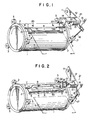
- Fig. 1 is a perspective view, showing a printing drum of a rotary stencil printing device with a stencil master wrapped around it, the leading edge of said stencil master being secured along a generator of the drum by the preferred embodiment of the system for retaining a stencil master to a printing drum according to the present invention
- Fig. 2 is a perspective view, similar to Fig. 1, showing said printing drum of said rotary stencil printing device with said stencil master being released from said generator of the drum by the preferred embodiment of the present invention.
- Fig. 1 shows in perspective view a printing drum 1 of a rotary stencil printing device of the type described earlier, having a perforated wall, with the leading edge of a stencil master S secured to it.
- the printing drum 1 is rotatably mounted by guide surfaces 2 formed on its axially extreme circumferential portions, which are each supported by a plurality of rollers 3, so as to be able to turn around its axis, and the leading edge of the stencil master S is retained and fixed along a generator of the printing drum 1 by a preferred embodiment of the system for retaining a leading edge of a stencil master to a printing drum according to the present invention.
- the rollers 3 are themselves supported by a framework not shown in the figures.
- the printing drum 1 has a preferred direction of rotation while the apparatus is being used for printing as indicated by the arrows in Figs. 1 and 2, and, by this mere fixing of the leading edge of the stencil master S to the printing drum 1 without any other part of the stencil master S being fixed, said stencil master S is kept securely wrapped around the drum, by a self wrapping effect supported by the adhesive effect of viscous printing ink supplied from the inside of the printing drum 1 through the perforations formed in its wall.
- a stage portion 5 is provided on the outer surface of the printing drum 1, extending approximately along said one of the generators thereof, and in a groove, not shown, formed in the flat outer surface of this stage portion 5 there is embedded a permanent magnet strip 6, so that the outer surface 6a of the magnet strip 6 is substantially flush with the outer surface of the stage portion 5, extending substantially along said generator of the printing drum 1.
- the permanent magnet strip 6 should be made of multipole magnet rubber strip of a per se well known sort, so that the outer surface 6a thereof is soft and provides a high frictional coefficient, and so that the attractive magnetic force exerted by the magnet strip 6 should be effected in a uniform distribution over the whole length of the magnet strip 6.
- two bearing brackets or hinges 7 are provided, one at each of the ends of the stage portion 5, and each of these brackets 7 pivotally supports one of two pivots 9, which are provided on the opposite ends of a clamp strip 8 which is shaped as an elongated rectangle; in more detail, the pivots 9 are mounted to the clamp strip 8 at opposite ends of one of the long sides thereof, extending in the same line as said long side.
- the clamp strip 8 is provided as extending generally along the magnet strip 6 with its one long side pivoted to the drum 1 by the pivots 9 and the hinges 7, and thus extending along said generator of the printing drum 1.
- the clamp strip 8 is made of a stiff magnetically susceptible material which is attracted by a magnetic field, such as for example stainless steel strip, and by the pivoting of the pivots 9 and the hinges 7 the clamp strip 8 can be moved between two extreme positions: a first extreme position shown in Fig. 1, in which said clamp strip 8 is laid against the permanent magnet strip 6 with the interposition of the leading edge of the stencil sheet S therebetween, in which first extreme position said clamp strip 8 is attracted by the permanent magnet strip 6 with considerable force so that they clamp the leading edge of the stencil sheet S between them, and a second extreme position shown in Fig.
- a driving unit for moving the clamp strip 8 between its two said extreme positions described above generally denoted by the reference numeral 21.
- a support frame not shown in the drawings there is pivoted by a pivot 11 one end of a lever 12, to which there is fitted an electric motor 13.
- This electric motor 13 has a power output shaft 14 which extends in the horizontal direction from the point of view of the figures, parallel to said generator of the printing drum 1 and to the hinges 7 and the pivots 9, on which second gear wheel 15 is fixedly mounted, as a drive gear opposing the gear wheel 10 on the pivot 9 in the transverse direction to their axes.
- the electric motor 13 is controlled as will hereinafter be explained.
- the lever 12 and the electric motor 13 mounted thereon, etc. can be rotated by pivoting around the pivot 11 either to a first position shown in Fig. 1, in which, irrespective of the rotary position of the printing drum 1, the drive gear wheel 15 is disengaged from the gear wheel 10 and thus the electric motor 13 is drivingly disconnected from the clamp strip 8 and cannot rotate it, or to a second position shown in Fig.
- a tension coil spring 16 biases the lever 12 in the anticlockwise direction in the figures, so as, if no actuating electrical energy is supplied to the solenoid 17, to pull said lever 12 and said electric motor 13, etc., in the anticlockwise direction in the figures to their said first position shown in Fig. 1 in which the drive gear wheel 15 is disconnected from the gear wheel 10; whereas on the other hand, if the solenoid 17 is supplied with actuating electrical energy, then it pulls the lever 12, etc., in the clockwise direction in the figures against the biasing action of the tension coil spring 16 which is overcome to their said second position shown in Fig. 2 in which the drive gear wheel 15 is meshed with the gear wheel 10.
- the solenoid device 17 and the electric motor 13 are selectively supplied with actuating electrical energy from a controller which will not be particularly described herein with regards to its structure but only in terms of its appropriate function, since these functions are periodic operations which can be performed by a controller of a per se well known type employing conventional sequence control technology, and thus various detailed structures therefor will be easily supplemented, if required, by one of ordinary skill in the relevant art.
- the device described above operates as follows.
- the device when an old used stencil master is to be discarded after having been used for stencil printing and the leading edge of a new stencil master is to be fixed to the printing drum 1 for a new episode of stencil printing, the device is in the position shown in Fig. 1, with the clamp strip 8 positioned in its extreme position where it is magnetically attached to the permanent magnet strip 6 with the leading edge of the stencil master S being clamped therebetween, with the driving unit 21 positioned to its upper position by the biasing action of the tension coil spring 16 with no actuating electrical energy being supplied to the solenoid device 17 so as to disengage the driving gear wheel 15 from the gear wheel 10, and with the printing drum 1 just having been positioned to its rotary position for master attachment and removal as shown in the figures with said permanent magnet strip 6 and said clamp strip 8, etc., opposed to the driving unit 21.
- the electric motor 13 is appropriately supplied with actuating electrical energy, and the gear wheel 10, the pivots 9, and the clamp strip 8 fixed thereto are rotated in the anticlockwise direction as seen in the figures, so as to move said clamp strip 8 about the axis of the pivots 9 via the intermediate position shown in Fig. 2 by the solid lines to its opposite extreme position to the one described above, i.e. to its position as shown in Fig. 2 by the phantom lines in which it is attracted by the two permanent magnets 20 and is turned approximately an angle of 180° away from the permanent magnet strip 6, thus releasing the leading edge of the stencil master S.
- the stencil master S is removed from the drum 1; this may be done mechanically and automatically, by for example a pick off or peeling off claw, although the details are not shown herein because they are not part of the present invention.
- the electric motor 13 is appropriately supplied with actuating electrical energy, this time in such a way as to operate it in the reverse rotary direction to the one used previously for removal of the stencil master, and the gear wheel 10, the pivots 9, and the clamp strip 8 fixed thereto are rotated in the clockwise direction as seen in the figures, so as to move said clamp strip 8 about the axis of the pivots 9 to the intermediate position shown in Fig. 2 by the solid lines, in which the clamp strip 8 makes an acute angle of about 45° with the magnet strip 6 and the upper surface in the figures of the stage portion 5.
- the electric motor 13 is deactivated, so as to stop this rotary motion of the clamp strip 8, and next the leading edge of the stencil master S is laid along the aforesaid generator of the drum 1, on top of the soft upper surface 6a of the permanent magnet strip 6 on the stage portion 5, by being fed theretowards; this may be done mechanically and automatically, although the details are not shown herein because they are not part of the present invention.
- the leading edge of the stencil master S may be fed into this acute angle of about 45° between the clamp strip 8 and the magnet strip 2 or the top surface of the stage portion 5, and thus may be conveniently aided with being located in proper position; this is the reason for setting the clamp strip 8 to its intermediate position as explained above.
- This leading edge of the stencil master S is not particularly reinforced, but is just made of the same material as the remainder of the stencil master S, i.e. of a thin plastic material.
- the stencil master S is wrapped onto the drum 1; the details of the supply of this stencil master S are not shown herein because again they are not part of the present invention.
- the clamp strip 8 and the permanent magnet strip 6 mutually clamp said leading edge of the stencil master S securely along said generator of the printing drum 1.
- the clamp strip 8 is made of suitable elasticity, rigidity, thickness, and so on to be well and strongly attracted by the magnet action of the permanent magnet strip 6. And the upper surface 6a of the permanent magnet strip 6 is made to be soft both in order not to damage the stencil master S and in order to have a good frictional coefficient thereagainst. According to this preferred embodiment, far from any form of reinforced lug or strip being required along the leading edge of the stencil master S, it is actually best for this leading edge to be left naked and thin, in order for the magnetic attraction between the clamp strip 8 and the permanent magnet strip 6 to be maximized by them being approached together as closely as possible.
- this system for retaining a stencil master to a printing drum is well adapted to the use of headless stencil masters which have no reinforced lug edge portions, and this is well adapted to a rotary stencil printing device in which the stencil masters are cut off from a roll of stencil master as and when required. Further, no delicate alignment process for the stencil master is required, during use of the retaining system therefor according to the present invention. Accordingly, this preferred embodiment of the present invention is particularly well suited for use in a fully automatic stencil printing device, in which the charging and discharging of the stencil masters are both performed entirely automatically.
Landscapes
- Screen Printers (AREA)
- Feeding Of Articles By Means Other Than Belts Or Rollers (AREA)
Description
- The present invention relates to a system for retaining a leading edge of a stencil master to a cylindrical printing drum of a stencil printing device, according to the pre-characterizing portion of claim 1.
- A certain type of rotary stencil printing device which incorporates a hollow printing drum around which a printing stencil master is wrapped is becoming widely used. In such a stencil printing device, printing ink is supplied from within the drum through perforations which extend from its inside space to its outer surface to the radially inner surface of the stencil master wrapped around the drum, and some of this ink passes through multiple perforations in certain previously perforated parts of the stencil master to the radially outward surface of the stencil master, whence this ink is then able to be transferred to the surface of a sheet of printing paper pressed against said outer surface of the stencil master, as the printing drum with the stencil master wrapped around it is rotated.
- In such a rotary stencil printing device, a means is required to be provided for retaining a leading edge of the stencil master along a generator of the printing drum, so that the stencil master is wrapped around the printing drum with a proper tension being applied thereto and the stencil sheet adhered around the printing drum by a viscous ink does not shift relative to the printing drum during the rotary stencil printing process.
- For use with currently manufactured conventional stencil printing devices, the leading edge of the stericil master is formed with a reinforced lug portion, made for example of cardboard, and this lug portion is formed with a plurality of perforated engaging holes therein, and along the generator of the printing drum there are provided a number of engagement projections corresponding to these engaging holes, the cardboard lug portion thus being retained against the printing drum along said generator with the engagement projections engaged into the engaging holes. A clamp strip is generally provided to mechanically press the cardboard lug portion mechanically to the printing drum along said generator, or such a clamp strip may be omitted when the engagement between the holes and the projections is formed to be of a non-return type.
- These conventional constructions for clamping the leading edge of the stencil master to the printing drum operate generally satisfactorily. However, there is still required a delicate and tedious hand job of of properly aligning the lug portion of the stencil master against the generator of the printing drum in a proper position for the engagement projections to be properly engaged into the engaging holes, and this fatally obstructs automation of the process of mounting and demounting of a stencil master to a printing drum. Further, because the stencil master, with this form of stencil retaining system, is required to have the above mentioned reinforcing lug provided along its leading edge, it is not possible to utilize continuous stencil master which is cut off from a roll of stencil master as and when required, but instead the stencil master sheets must be individually manufactured in advance with reinforcing lugs thereon, which is expensive. The use of a headless stencil master, which is typically a piece of plastic material of the thickness of a few tens of microns, without any particular construction for the leading edge thereof, is a very desirable object for implementation in a stencil printing device, and accordingly the prior art schemes for retaining a leading edge of a stencil master onto a printing drum of a rotary stencil printing device are seriously deficient.
- The Xerox Disclosure Journal vo. 3 No. 2, March/April 1978 page 107 shows in principle a system for retaining the leading edge of a docu- men sheet, which may as well be useful for headless stencil masters. The leading and the trailing edge of the sheet are attached to the drum in a position, where the drum surface is provided with a recess containing a permanent magnet strip, by a pair of ferromagnetic gripper bars. These bars are both hinged to the cylindrical printing drum along a pivot line extending in the middle of the magnet strip.
- To attach the leading edge of the document sheet, especially the headless stencil master, it is inserted into the clearance between the drum and the bar, which has been brought into its open position. During this insertion an accurate alignment of the leading edge of the headless stencil master and the box, respectively the pivot line, can only be achieved with special complicated measures.
- It is the object of the invention to further develop the system for retaining the leading edge of headless a stencil master to a printing drum, so that it does not require any delicate alignment process, which system is well adapted to be used in a automatic rotary stencil printing device in which the stencil masters are mounted and demounted automatically, and is as well easily operated, reliable and cheap in its construction.
- This object is accomplished by a system for retaining a leading edge of a stencil master to a cylindrical printing drum of a stencil printing device, which is provided with the features of the characterizing portion of claim 1.
- Such a system is useful for headless stencil masters which have no reinforced lug edge portions, for instance ones which are cut off from a roll of stencil master as and when required. This system does not require any delicate alignment process for the stencil master because the clamp strip is so pivoted as to form an acute angle with the portion of the printing drum surface on which the magnet strip is provided, and the leading edge of the stencil master may be fed into this acute angle, which is convenient for locating this leading edge for the stencil master accurately. This system is well adapted to use in an automatic rotary stencil printing device in which the stencil masters are mounted and demounted automatically. The apparatus itself is of a relatively cheap construction, and further is cheap during use, as it can use a continuous sheet type stencil master.
- Further the magnet strip may be made of rubberized magnet material. In this case, the risk of damage to the stencil master during securing of it and the risk of the leading edge of the stencil master becoming escaped from the clamping during stencil printing are both reduced, since such rubberized magnet material is relatively soft and also provides an increased friction coefficient.
- According to
claim 2, when said clamp strip is hinged away from said magnet strip so as to release the leading edge of the stencil master, it may be hinged right over through an angle of approximately 180°, so as to be attracted by said permanent magnet and so as to be thereby securely held in place. This is very helpful for ensuring that said clamp strip does not accidentally become pivoted against said magnet strip, during the process of removal of a used stencil master, which usually involves rotation of the printing drum with the leading edge of the used stencil master being thus released. - In a construction according to
claim 3 the means for mechanically rotating the clamp strip may be used either to rotate said clamp strip towards said magnet strip so as to clamp the leading edge of a stencil master which is to be used for stencil printing as explained above, or to rotate said clamp strip away from said magnet strip so as to release said leading edge of said stencil master when the stencil printing therefrom has been completed, so as to dispose of said used stencil master. This particular construction is very suitable for use in an automatic type of stencil printing device in which the stencil are charged and discharged automatically. - The construction according to
claim 6 and especiallyclaim 7 is very helpful for ensuring that said printing drum does not rotate about is axis, during the process of rotating the clamp strip about its axis to secure or to release the leading edge of a stencil master as explained above. In the case that the construction described above employing a first and a second gear wheel for mechanically rotating the clamp strip is utilized, then this second gear wheel may be optionally coupled in its transverse motion to said bracket while of course being rotatable with respect thereto, so that said second gear wheel comes to be engaged with said first gear wheel as said bracket is moved towards the axis of said printing drum, and comes to be disengaged from said first gear wheel as said bracket is moved away from the axis of said printing drum. - Thus, in the case, this motion of the bracket is advantageously used for two separate purposes.
- Further advantages of the invention are achieved, if it is additionally provided with one or more of the features of the other subclaims.
- Fig. 1 is a perspective view, showing a printing drum of a rotary stencil printing device with a stencil master wrapped around it, the leading edge of said stencil master being secured along a generator of the drum by the preferred embodiment of the system for retaining a stencil master to a printing drum according to the present invention; and
- Fig. 2 is a perspective view, similar to Fig. 1, showing said printing drum of said rotary stencil printing device with said stencil master being released from said generator of the drum by the preferred embodiment of the present invention.
- The present invention will now be described with reference to the preferred embodiment thereof. Fig. 1 shows in perspective view a printing drum 1 of a rotary stencil printing device of the type described earlier, having a perforated wall, with the leading edge of a stencil master S secured to it. The printing drum 1 is rotatably mounted by
guide surfaces 2 formed on its axially extreme circumferential portions, which are each supported by a plurality ofrollers 3, so as to be able to turn around its axis, and the leading edge of the stencil master S is retained and fixed along a generator of the printing drum 1 by a preferred embodiment of the system for retaining a leading edge of a stencil master to a printing drum according to the present invention. Therollers 3 are themselves supported by a framework not shown in the figures. The printing drum 1 has a preferred direction of rotation while the apparatus is being used for printing as indicated by the arrows in Figs. 1 and 2, and, by this mere fixing of the leading edge of the stencil master S to the printing drum 1 without any other part of the stencil master S being fixed, said stencil master S is kept securely wrapped around the drum, by a self wrapping effect supported by the adhesive effect of viscous printing ink supplied from the inside of the printing drum 1 through the perforations formed in its wall. - A
stage portion 5 is provided on the outer surface of the printing drum 1, extending approximately along said one of the generators thereof, and in a groove, not shown, formed in the flat outer surface of thisstage portion 5 there is embedded apermanent magnet strip 6, so that the outer surface 6a of themagnet strip 6 is substantially flush with the outer surface of thestage portion 5, extending substantially along said generator of the printing drum 1. It is desirable that thepermanent magnet strip 6 should be made of multipole magnet rubber strip of a per se well known sort, so that the outer surface 6a thereof is soft and provides a high frictional coefficient, and so that the attractive magnetic force exerted by themagnet strip 6 should be effected in a uniform distribution over the whole length of themagnet strip 6. - Further, two bearing brackets or
hinges 7 are provided, one at each of the ends of thestage portion 5, and each of thesebrackets 7 pivotally supports one of twopivots 9, which are provided on the opposite ends of aclamp strip 8 which is shaped as an elongated rectangle; in more detail, thepivots 9 are mounted to theclamp strip 8 at opposite ends of one of the long sides thereof, extending in the same line as said long side. Thus theclamp strip 8 is provided as extending generally along themagnet strip 6 with its one long side pivoted to the drum 1 by thepivots 9 and thehinges 7, and thus extending along said generator of the printing drum 1. Theclamp strip 8 is made of a stiff magnetically susceptible material which is attracted by a magnetic field, such as for example stainless steel strip, and by the pivoting of thepivots 9 and thehinges 7 theclamp strip 8 can be moved between two extreme positions: a first extreme position shown in Fig. 1, in which saidclamp strip 8 is laid against thepermanent magnet strip 6 with the interposition of the leading edge of the stencil sheet S therebetween, in which first extreme position saidclamp strip 8 is attracted by thepermanent magnet strip 6 with considerable force so that they clamp the leading edge of the stencil sheet S between them, and a second extreme position shown in Fig. 2 by the phantom lines, in which saidclamp strip 8 is pivoted through an angle of approximately 180° from said first extreme position, and is laid against the printing drum 1 away from saidpermanent magnet strip 6 and away from said leading edge of said stencil sheet S, in which second position saidclamp strip 8 and saidpermanent magnet strip 6 release said leading edge of the stencil sheet S, as indicated in Fig. 2. The position of saidclamp strip 8 shown by the solid lines in Fig. 2 is an intermediate position between the above described first and second extreme positions thereof. When theclamp strip 8 is in its above described second extreme position, in which it is pivoted away from the leading edge of the stencil sheet S and away from thepermanent magnet strip 6, it is pulled against and held by a pair ofpermanent magnets 20 embedded in the outer surface of the printing drum 1, which thus retain saidclamp strip 8 in this second extreme position thereof. On the outside end of one of thepivots 9 there is fixedly mounted a first gear wheel 10, for driving this rotation of theclamp strip 8 as will hereinafter be explained. - Generally above the printing drum 1 from the point of view of Figs. 1 and 2, there is provided a driving unit for moving the
clamp strip 8 between its two said extreme positions described above, generally denoted by thereference numeral 21. To a support frame not shown in the drawings there is pivoted by apivot 11 one end of alever 12, to which there is fitted anelectric motor 13. Thiselectric motor 13 has apower output shaft 14 which extends in the horizontal direction from the point of view of the figures, parallel to said generator of the printing drum 1 and to thehinges 7 and thepivots 9, on whichsecond gear wheel 15 is fixedly mounted, as a drive gear opposing the gear wheel 10 on thepivot 9 in the transverse direction to their axes. Theelectric motor 13 is controlled as will hereinafter be explained. - The
lever 12 and theelectric motor 13 mounted thereon, etc., can be rotated by pivoting around thepivot 11 either to a first position shown in Fig. 1, in which, irrespective of the rotary position of the printing drum 1, thedrive gear wheel 15 is disengaged from the gear wheel 10 and thus theelectric motor 13 is drivingly disconnected from theclamp strip 8 and cannot rotate it, or to a second position shown in Fig. 2, in which, provided that the printing drum 1, with theclamp strip 8 mounted thereto are in their rotary position as shown in the figures in which the axis of thepivots 9 and the pivoted edge of theclamp strip 8 is at its closest to the axis of thepower output shaft 14 of the electric motor 13 (this will hereinafter be referred to as the rotary position of the printing drum 1 for master attachment and removal), thedrive gear wheel 15 is meshed with the gear wheel 10 0 and thus theelectric motor 13 is drivingly connected to theclamp strip 8 and can rotate it. This rotation of thelever 12, etc., is performed by a construction which comprises asolenoid 17, fixed to the frame not shown in the figures. Theplunger 18 of thesolenoid 17 is pivotally engaged to the end of thelever 12 remote from thepivot 11. Atension coil spring 16 biases thelever 12 in the anticlockwise direction in the figures, so as, if no actuating electrical energy is supplied to thesolenoid 17, to pull saidlever 12 and saidelectric motor 13, etc., in the anticlockwise direction in the figures to their said first position shown in Fig. 1 in which thedrive gear wheel 15 is disconnected from the gear wheel 10; whereas on the other hand, if thesolenoid 17 is supplied with actuating electrical energy, then it pulls thelever 12, etc., in the clockwise direction in the figures against the biasing action of thetension coil spring 16 which is overcome to their said second position shown in Fig. 2 in which thedrive gear wheel 15 is meshed with the gear wheel 10. Finally, on thelever 12 there is provided anengaging bracket 19 with aslot 22 formed in a protruding end portion thereof, so arranged that, when saidlever 12 and the associated parts are in their said second position shown in Fig. 2 in which thedrive gearwheel 15 is meshed with the gear wheel 10, theslot 22 is accurately engaged over thehinge 7 associated with the gear wheel 10, thus holding the printing drum 1 securely in said rotary position thereof for master attachment and removal. - The
solenoid device 17 and theelectric motor 13 are selectively supplied with actuating electrical energy from a controller which will not be particularly described herein with regards to its structure but only in terms of its appropriate function, since these functions are periodic operations which can be performed by a controller of a per se well known type employing conventional sequence control technology, and thus various detailed structures therefor will be easily supplemented, if required, by one of ordinary skill in the relevant art. - The device described above operates as follows.
- First, when an old used stencil master is to be discarded after having been used for stencil printing and the leading edge of a new stencil master is to be fixed to the printing drum 1 for a new episode of stencil printing, the device is in the position shown in Fig. 1, with the
clamp strip 8 positioned in its extreme position where it is magnetically attached to thepermanent magnet strip 6 with the leading edge of the stencil master S being clamped therebetween, with thedriving unit 21 positioned to its upper position by the biasing action of thetension coil spring 16 with no actuating electrical energy being supplied to thesolenoid device 17 so as to disengage thedriving gear wheel 15 from the gear wheel 10, and with the printing drum 1 just having been positioned to its rotary position for master attachment and removal as shown in the figures with saidpermanent magnet strip 6 and saidclamp strip 8, etc., opposed to thedriving unit 21. From this state, when the controller not particularly described herein so decides, next thesolenoid device 17 is supplied by this controller with actuating electrical energy, so that thelever 12 is pivoted clockwise as seen in the figures against the biasing action of thetension coil spring 16 which is overcome, and thus thedriving unit 21 is lowered downwards in the figures towards the printing drum 1 to the position shown in Fig. 2 in which thedriving gear wheel 15 is meshed with the gear wheel 10, and theslot 22 on thebracket 19 is positively holding thehinge 7 and thus fixing the printing drum 1 in its said rotary position for master attachment and removal. Next, theelectric motor 13 is appropriately supplied with actuating electrical energy, and the gear wheel 10, thepivots 9, and theclamp strip 8 fixed thereto are rotated in the anticlockwise direction as seen in the figures, so as to move saidclamp strip 8 about the axis of thepivots 9 via the intermediate position shown in Fig. 2 by the solid lines to its opposite extreme position to the one described above, i.e. to its position as shown in Fig. 2 by the phantom lines in which it is attracted by the twopermanent magnets 20 and is turned approximately an angle of 180° away from thepermanent magnet strip 6, thus releasing the leading edge of the stencil master S. During this phase of rotating theclamp strip 8, the holding of the printing drum 1 positively in its said rotary position for master attachment and removal by theslot 22 on thebracket 19 being engaged with thehinge 7 is most helpful for ensuring that the mutual reaction between thedriving gear wheel 15 and the gear wheel 10 is not able to rotate the printing drum even slightly, which might cause these gear wheels to come out of mesh with one another; this is a particular good feature of the shown preferred embodiment of the present invention. Next, the supply of actuating electrical energy to theelectric motor 13 is cut off, so that the movement of theclamp strip 8 is stopped, and also the supply of actuating electrical energy to thesolenoid 17 is cut off, so that thelever 12 is rotated in the anticlockwise direction in the figures and thedriving unit 21 is repositioned to its upper position by the biasing action of thetension coil spring 16, and so that thedriving gear wheel 15 is disengaged from the gear wheel 10, with theslot 22 on thebracket 19 now releasing thehinge 7 and thus releasing the printing drum 1 so that it is free to rotate. At this time, the printing drum is now free to rotate, and the leading edge of the stencil master S is released from being retained to thepermanent magnet strip 6 of the printing drum 1. Subsequently, as the printing drum 1 is rotated, the stencil master S is removed from the drum 1; this may be done mechanically and automatically, by for example a pick off or peeling off claw, although the details are not shown herein because they are not part of the present invention. - Next, in order to fix the leading edge of a new stencil master to the printing drum 1 for a new episode of stencil printing, when the old stencil master has been disposed of and the device has been repositioned to its rotary position for master attachment and removal with the
clamp strip 8 still positioned in its extreme position where it is magnetically attached to thepermanent magnets 20 away from themagnet strip 6, and with thedriving unit 21 positioned to its upper position by the biasing action of thetension coil spring 16 with no actuating electrical energy being supplied to thesolenoid device 17 so as to disengage thedriving gear wheel 15 from the gear wheel 10, then from this state, when the controller not particularly described herein so decides, next thesolenoid device 17 is again supplied by this controller with actuating electrical energy, so that thelever 12 is pivoted clockwise as seen in the figures against the biasing action of thetension coil spring 16 which is overcome, and thus thedriving unit 21 is again lowered downwards in the figures towards the printing drum 1 to the position shown in Fig. 2 in which thedriving gear wheel 15 is meshed with the gear wheel 10, and theslot 22 on thebracket 19 is again positively holding thehinge 7 and thus fixing the printing drum 1 in its said rotary position for master attachment and removal. Next, theelectric motor 13 is appropriately supplied with actuating electrical energy, this time in such a way as to operate it in the reverse rotary direction to the one used previously for removal of the stencil master, and the gear wheel 10, thepivots 9, and theclamp strip 8 fixed thereto are rotated in the clockwise direction as seen in the figures, so as to move saidclamp strip 8 about the axis of thepivots 9 to the intermediate position shown in Fig. 2 by the solid lines, in which theclamp strip 8 makes an acute angle of about 45° with themagnet strip 6 and the upper surface in the figures of thestage portion 5. During this phase of rotating theclamp strip 8, the holding of the printing drum 1 positively in its said rotary position for master attachment and removal by theslot 22 on thebracket 19 being engaged with thehinge 7 is again most helpful for ensuring that the mutual reaction between the drivinggear wheel 15 and the gear wheel 10 is not able to rotate the printing drum even slightly, which might cause these gear wheels to come out of mesh with one another; this is a particular - good feature of the shown preferred embodiment of the present invention. Next, the
electric motor 13 is deactivated, so as to stop this rotary motion of theclamp strip 8, and next the leading edge of the stencil master S is laid along the aforesaid generator of the drum 1, on top of the soft upper surface 6a of thepermanent magnet strip 6 on thestage portion 5, by being fed theretowards; this may be done mechanically and automatically, although the details are not shown herein because they are not part of the present invention. Conveniently the leading edge of the stencil master S may be fed into this acute angle of about 45° between theclamp strip 8 and themagnet strip 2 or the top surface of thestage portion 5, and thus may be conveniently aided with being located in proper position; this is the reason for setting theclamp strip 8 to its intermediate position as explained above. This leading edge of the stencil master S is not particularly reinforced, but is just made of the same material as the remainder of the stencil master S, i.e. of a thin plastic material. When this operation is completed, the fact is detected by a sensor not shown in the figure, associated with the abovementioned sequence control device for theelectric motor 13 and thesolenoid device 17, and next theelectric motor 13 is appropriately supplied with actuating electrical energy, again in such a way as to operate it in the reverse rotary direction to the one used previously for removal of the stencil master, and the gear wheel 10, thepivots 9, and theclamp strip 8 fixed thereto are continued to be rotated in the clockwise direction as seen in the figures, so as to move saidclamp strip 8 about the axis of thepivots 9 from the intermediate position shown in Fig. 2 by the solid lines to its position as shown in Fig. 1 in which it is attracted by thepermanent magnet strip 6, so that theclamp strip 8 comes to be laid on the top of the leading edge of the stencil master S, against said soft upper surface 6a of thepermanent magnet strip 6 with the interposition of said leading edge of the stencil master S, as shown in Fig. 1, thus securely gripping the leading edge of the stencil master S between itself and saidpermanent magnet strip 6. Next, the supply of actuating electrical energy to theelectric motor 13 is cut off, so that the movement of theclamp strip 8 is stopped, and also the supply of actuating electrical energy to thesolenoid 17 is cut off, so that thelever 12 is again rotated in the anticlockwise direction in the figures and the drivingunit 21 is repositioned to its upper position by the biasing action of thetension coil spring 16, and so that thedriving gear wheel 15 is disengaged from the gear wheel 10, with theslot 22 on thebracket 19 now again releasing thehinge 7 and thus releasing the printing drum 1 so that it is once more free to rotate. At this time, the printing drum is now free to rotate, and the leading edge of the new stencil master S is securely retained to the generator of the printing drum 1, being held between thepermanent magnet strip 6 and theclamp strip 8. Subsequently, as the printing drum 1 is rotated, the stencil master S is wrapped onto the drum 1; the details of the supply of this stencil master S are not shown herein because again they are not part of the present invention. Thus, by the mutual attraction between theclamp strip 8 and thepermanent magnet strip 6, they mutually clamp said leading edge of the stencil master S securely along said generator of the printing drum 1. - The
clamp strip 8 is made of suitable elasticity, rigidity, thickness, and so on to be well and strongly attracted by the magnet action of thepermanent magnet strip 6. And the upper surface 6a of thepermanent magnet strip 6 is made to be soft both in order not to damage the stencil master S and in order to have a good frictional coefficient thereagainst. According to this preferred embodiment, far from any form of reinforced lug or strip being required along the leading edge of the stencil master S, it is actually best for this leading edge to be left naked and thin, in order for the magnetic attraction between theclamp strip 8 and thepermanent magnet strip 6 to be maximized by them being approached together as closely as possible. Thus, this system for retaining a stencil master to a printing drum is well adapted to the use of headless stencil masters which have no reinforced lug edge portions, and this is well adapted to a rotary stencil printing device in which the stencil masters are cut off from a roll of stencil master as and when required. Further, no delicate alignment process for the stencil master is required, during use of the retaining system therefor according to the present invention. Accordingly, this preferred embodiment of the present invention is particularly well suited for use in a fully automatic stencil printing device, in which the charging and discharging of the stencil masters are both performed entirely automatically.
Claims (8)
Applications Claiming Priority (2)
| Application Number | Priority Date | Filing Date | Title |
|---|---|---|---|
| JP57207217A JPS5996984A (en) | 1982-11-26 | 1982-11-26 | Stencil paper retaining device for printer |
| JP207217/82 | 1982-11-26 |
Publications (2)
| Publication Number | Publication Date |
|---|---|
| EP0111050A1 EP0111050A1 (en) | 1984-06-20 |
| EP0111050B1 true EP0111050B1 (en) | 1986-11-05 |
Family
ID=16536180
Family Applications (1)
| Application Number | Title | Priority Date | Filing Date |
|---|---|---|---|
| EP83107975A Expired EP0111050B1 (en) | 1982-11-26 | 1983-08-11 | System for retaining stencil printing master on printing drum by clamp strip hinged along drum generator |
Country Status (4)
| Country | Link |
|---|---|
| US (1) | US4505199A (en) |
| EP (1) | EP0111050B1 (en) |
| JP (1) | JPS5996984A (en) |
| DE (1) | DE3367350D1 (en) |
Families Citing this family (16)
| Publication number | Priority date | Publication date | Assignee | Title |
|---|---|---|---|---|
| JPS61104854A (en) * | 1984-10-29 | 1986-05-23 | Riso Kagaku Corp | Stencil paper retaining device for printer |
| JPH01501052A (en) * | 1986-10-29 | 1989-04-13 | ホルデレッガー ユルグ | Screen printing equipment including flat and flexible printing screens |
| JPS63176658U (en) * | 1987-05-01 | 1988-11-16 | ||
| US4974512A (en) * | 1988-05-26 | 1990-12-04 | Nu-Graphics Equipment, Inc. | Magnetic rotary locking and tensioning mechanism |
| US4878429A (en) * | 1988-05-26 | 1989-11-07 | Nu-Graphics Engineering, Inc. | Magnetic rotary locking mechanism and method |
| JP2728435B2 (en) * | 1988-06-22 | 1998-03-18 | 理想科学工業株式会社 | Stencil printing machine |
| US4890553A (en) * | 1989-02-16 | 1990-01-02 | Heath Custom Press, Inc. | Positioning and attachment means for flexible printing plates |
| JP2828462B2 (en) * | 1989-06-22 | 1998-11-25 | 理想科学工業株式会社 | Stencil printing machine |
| JP3280061B2 (en) * | 1992-03-13 | 2002-04-30 | 理想科学工業株式会社 | Stencil sheet feeding and discharging device |
| JP2795393B2 (en) * | 1993-04-26 | 1998-09-10 | 東北リコー株式会社 | Master locking device for stencil printing machine |
| JP3292775B2 (en) * | 1994-03-10 | 2002-06-17 | 理想科学工業株式会社 | Control method of connection drive unit of stencil printing machine |
| JP3292427B2 (en) * | 1994-11-25 | 2002-06-17 | 理想科学工業株式会社 | Stencil stencil starter for rotary stencil printing press |
| US6267054B1 (en) * | 1999-03-12 | 2001-07-31 | Creo Products Inc. | Retaining apparatus and method for holding printing plates on a vacuum drum |
| JP3631929B2 (en) | 1999-11-11 | 2005-03-23 | 理想科学工業株式会社 | Stencil paper starting edge mounting device of rotary stencil printing machine |
| US6729235B2 (en) | 2001-04-30 | 2004-05-04 | Eastman Kodak Company | Imaging apparatus and imaging drum having material clamp |
| NL1021417C2 (en) * | 2002-09-09 | 2004-03-10 | Stork Prints Bv | Printing cylinder support unit. |
Family Cites Families (19)
| Publication number | Priority date | Publication date | Assignee | Title |
|---|---|---|---|---|
| US786633A (en) * | 1904-05-10 | 1905-04-04 | Dick Co Ab | Stencil-duplicating apparatus. |
| FR368103A (en) * | 1906-07-17 | 1906-11-19 | John Thomas Underwood | Improvements to duplicating devices |
| CH108479A (en) * | 1924-02-28 | 1925-01-16 | Karman Marcel | Rubber sole. |
| FR596749A (en) * | 1924-07-22 | 1925-10-30 | Device for fixing stencils in so-called duplicating devices, and stencil suitable for this device | |
| GB259931A (en) * | 1925-10-17 | 1927-04-07 | Albert Nau Touron | An improved device for spinning textile materials or the like |
| US2237734A (en) * | 1937-08-05 | 1941-04-08 | William Smit | Stenciling |
| US2229059A (en) * | 1938-06-20 | 1941-01-21 | Rapidex Corp | Sheet attaching means for duplicators |
| US2231291A (en) * | 1939-09-02 | 1941-02-11 | Ditto Inc | Duplicating machine and block-out means therefor |
| DE899942C (en) * | 1941-05-27 | 1953-12-17 | Roto Werke A G | Holding device for stencils on multipliers |
| US2730948A (en) * | 1952-01-22 | 1956-01-17 | Addressograph Multigraph | Clamp for master sheets of printing machines |
| US2775199A (en) * | 1953-02-24 | 1956-12-25 | M B Claff & Sons Inc | Flexible printing plate locking device |
| CH317491A (en) * | 1953-07-28 | 1956-11-30 | Herzer Alfred E | Device for holding a print image carrier on the printing unit of printing machines |
| US3017545A (en) * | 1954-08-12 | 1962-01-16 | Alfred E Herzer | Device for magnetic clamping |
| FR1383860A (en) * | 1963-10-11 | 1965-01-04 | New impression cylinder for transfer machine | |
| SE317491B (en) * | 1968-04-03 | 1969-11-17 | Pitea Maskin Industri | |
| US3941054A (en) * | 1971-10-06 | 1976-03-02 | Heyer Inc. | Stencil gripping apparatus for a duplicating machine |
| JPS536304B2 (en) * | 1971-11-12 | 1978-03-07 | ||
| US3745626A (en) * | 1971-12-27 | 1973-07-17 | Magna Graphics Corp | Coating roll |
| JPS5423363U (en) * | 1977-07-19 | 1979-02-15 |
-
1982
- 1982-11-26 JP JP57207217A patent/JPS5996984A/en active Pending
-
1983
- 1983-07-29 US US06/518,422 patent/US4505199A/en not_active Expired - Lifetime
- 1983-08-11 DE DE8383107975T patent/DE3367350D1/en not_active Expired
- 1983-08-11 EP EP83107975A patent/EP0111050B1/en not_active Expired
Also Published As
| Publication number | Publication date |
|---|---|
| US4505199A (en) | 1985-03-19 |
| EP0111050A1 (en) | 1984-06-20 |
| JPS5996984A (en) | 1984-06-04 |
| DE3367350D1 (en) | 1986-12-11 |
Similar Documents
| Publication | Publication Date | Title |
|---|---|---|
| US4505199A (en) | System for retaining stencil printing master on printing drum by clamp strip hinged along drum generator | |
| EP0179986B1 (en) | Master retaining device for a printing machine | |
| CN1089707C (en) | Labeling machine | |
| US4528906A (en) | System for retaining stencil printing master on printing drum | |
| JPH02106555A (en) | Tape containing cassette | |
| JP2828462B2 (en) | Stencil printing machine | |
| KR100229988B1 (en) | Trial-order indicator mounting device for rotary type press | |
| JP4475742B2 (en) | Automatic plate detaching device | |
| EP0133849A1 (en) | System for retaining stencil printing master on printing drum | |
| KR20220004330A (en) | Labeling machine | |
| JPH068402A (en) | Device for automatic mounting and dismounting of form plate in imprinter | |
| JP2004231267A (en) | Label sticking device | |
| US6334387B1 (en) | Stencil printer having carriage for guiding leading end of stencil sheet | |
| US7128290B1 (en) | Spool having a dual purpose cam | |
| JP2024504756A (en) | Removable device for attaching endless ribbons | |
| US20080029022A1 (en) | Device for automatically pasting sheets of paper or cardboard | |
| EP0696512B1 (en) | Mimeographic printing machine | |
| JPH0126462Y2 (en) | ||
| JP2001010618A (en) | Label removal equipment | |
| JP2006137607A (en) | Printer and supply unit for use in printer | |
| JPH0126463Y2 (en) | ||
| JPS623250Y2 (en) | ||
| JPH0755089Y2 (en) | Stencil printing machine | |
| JP3713121B2 (en) | Printing book winding device and method of using the same | |
| JPH028135A (en) | Automatic peeling device for protective paper in newspaper rotary press |
Legal Events
| Date | Code | Title | Description |
|---|---|---|---|
| PUAI | Public reference made under article 153(3) epc to a published international application that has entered the european phase |
Free format text: ORIGINAL CODE: 0009012 |
|
| AK | Designated contracting states |
Designated state(s): DE FR GB |
|
| 17P | Request for examination filed |
Effective date: 19840918 |
|
| GRAA | (expected) grant |
Free format text: ORIGINAL CODE: 0009210 |
|
| AK | Designated contracting states |
Kind code of ref document: B1 Designated state(s): DE FR GB |
|
| REF | Corresponds to: |
Ref document number: 3367350 Country of ref document: DE Date of ref document: 19861211 |
|
| ET | Fr: translation filed | ||
| PLBE | No opposition filed within time limit |
Free format text: ORIGINAL CODE: 0009261 |
|
| STAA | Information on the status of an ep patent application or granted ep patent |
Free format text: STATUS: NO OPPOSITION FILED WITHIN TIME LIMIT |
|
| 26N | No opposition filed | ||
| REG | Reference to a national code |
Ref country code: GB Ref legal event code: IF02 |
|
| PGFP | Annual fee paid to national office [announced via postgrant information from national office to epo] |
Ref country code: GB Payment date: 20020730 Year of fee payment: 20 |
|
| PGFP | Annual fee paid to national office [announced via postgrant information from national office to epo] |
Ref country code: DE Payment date: 20020809 Year of fee payment: 20 |
|
| PGFP | Annual fee paid to national office [announced via postgrant information from national office to epo] |
Ref country code: FR Payment date: 20020812 Year of fee payment: 20 |
|
| PG25 | Lapsed in a contracting state [announced via postgrant information from national office to epo] |
Ref country code: GB Free format text: LAPSE BECAUSE OF EXPIRATION OF PROTECTION Effective date: 20030810 |
|
| REG | Reference to a national code |
Ref country code: GB Ref legal event code: PE20 |