CN1089707C - Labeling machine - Google Patents
Labeling machine Download PDFInfo
- Publication number
- CN1089707C CN1089707C CN99800818A CN99800818A CN1089707C CN 1089707 C CN1089707 C CN 1089707C CN 99800818 A CN99800818 A CN 99800818A CN 99800818 A CN99800818 A CN 99800818A CN 1089707 C CN1089707 C CN 1089707C
- Authority
- CN
- China
- Prior art keywords
- label
- base stock
- lax
- detecting device
- stuck
- Prior art date
- Legal status (The legal status is an assumption and is not a legal conclusion. Google has not performed a legal analysis and makes no representation as to the accuracy of the status listed.)
- Expired - Fee Related
Links
Images


Classifications
-
- B—PERFORMING OPERATIONS; TRANSPORTING
- B65—CONVEYING; PACKING; STORING; HANDLING THIN OR FILAMENTARY MATERIAL
- B65C—LABELLING OR TAGGING MACHINES, APPARATUS, OR PROCESSES
- B65C11/00—Manually-controlled or manually-operable label dispensers, e.g. modified for the application of labels to articles
- B65C11/006—Manually-controlled or manually-operable label dispensers, e.g. modified for the application of labels to articles using electrical or electro-mechanical means
-
- B—PERFORMING OPERATIONS; TRANSPORTING
- B65—CONVEYING; PACKING; STORING; HANDLING THIN OR FILAMENTARY MATERIAL
- B65C—LABELLING OR TAGGING MACHINES, APPARATUS, OR PROCESSES
- B65C11/00—Manually-controlled or manually-operable label dispensers, e.g. modified for the application of labels to articles
- B65C11/002—Manually-controlled or manually-operable label dispensers, e.g. modified for the application of labels to articles modified for the application of labels to articles
- B65C11/004—Manually-controlled or manually-operable label dispensers, e.g. modified for the application of labels to articles modified for the application of labels to articles label feeding from strips
-
- B—PERFORMING OPERATIONS; TRANSPORTING
- B65—CONVEYING; PACKING; STORING; HANDLING THIN OR FILAMENTARY MATERIAL
- B65C—LABELLING OR TAGGING MACHINES, APPARATUS, OR PROCESSES
- B65C11/00—Manually-controlled or manually-operable label dispensers, e.g. modified for the application of labels to articles
- B65C11/02—Manually-controlled or manually-operable label dispensers, e.g. modified for the application of labels to articles having printing equipment
- B65C11/0289—Manually-controlled or manually-operable label dispensers, e.g. modified for the application of labels to articles having printing equipment using electrical or electro-mechanical means
-
- B—PERFORMING OPERATIONS; TRANSPORTING
- B65—CONVEYING; PACKING; STORING; HANDLING THIN OR FILAMENTARY MATERIAL
- B65C—LABELLING OR TAGGING MACHINES, APPARATUS, OR PROCESSES
- B65C2210/00—Details of manually controlled or manually operable label dispensers
- B65C2210/0072—Specific details of different parts
- B65C2210/0078—Peeling devices
-
- B—PERFORMING OPERATIONS; TRANSPORTING
- B65—CONVEYING; PACKING; STORING; HANDLING THIN OR FILAMENTARY MATERIAL
- B65C—LABELLING OR TAGGING MACHINES, APPARATUS, OR PROCESSES
- B65C2210/00—Details of manually controlled or manually operable label dispensers
- B65C2210/0072—Specific details of different parts
- B65C2210/0086—Specific details of different parts platens
-
- B—PERFORMING OPERATIONS; TRANSPORTING
- B65—CONVEYING; PACKING; STORING; HANDLING THIN OR FILAMENTARY MATERIAL
- B65C—LABELLING OR TAGGING MACHINES, APPARATUS, OR PROCESSES
- B65C2210/00—Details of manually controlled or manually operable label dispensers
- B65C2210/0072—Specific details of different parts
- B65C2210/0094—Label sensing devices
-
- Y—GENERAL TAGGING OF NEW TECHNOLOGICAL DEVELOPMENTS; GENERAL TAGGING OF CROSS-SECTIONAL TECHNOLOGIES SPANNING OVER SEVERAL SECTIONS OF THE IPC; TECHNICAL SUBJECTS COVERED BY FORMER USPC CROSS-REFERENCE ART COLLECTIONS [XRACs] AND DIGESTS
- Y10—TECHNICAL SUBJECTS COVERED BY FORMER USPC
- Y10T—TECHNICAL SUBJECTS COVERED BY FORMER US CLASSIFICATION
- Y10T156/00—Adhesive bonding and miscellaneous chemical manufacture
- Y10T156/17—Surface bonding means and/or assemblymeans with work feeding or handling means
- Y10T156/1702—For plural parts or plural areas of single part
- Y10T156/1705—Lamina transferred to base from adhered flexible web or sheet type carrier
- Y10T156/1707—Discrete spaced laminae on adhered carrier
- Y10T156/171—Means serially presenting discrete base articles or separate portions of a single article
-
- Y—GENERAL TAGGING OF NEW TECHNOLOGICAL DEVELOPMENTS; GENERAL TAGGING OF CROSS-SECTIONAL TECHNOLOGIES SPANNING OVER SEVERAL SECTIONS OF THE IPC; TECHNICAL SUBJECTS COVERED BY FORMER USPC CROSS-REFERENCE ART COLLECTIONS [XRACs] AND DIGESTS
- Y10—TECHNICAL SUBJECTS COVERED BY FORMER USPC
- Y10T—TECHNICAL SUBJECTS COVERED BY FORMER US CLASSIFICATION
- Y10T156/00—Adhesive bonding and miscellaneous chemical manufacture
- Y10T156/18—Surface bonding means and/or assembly means with handle or handgrip
Abstract
A labeling machine wherein a continuous label sheet (R) having a mount (S) on which a plurality of printed labels (L) are stuck temporarily is fed from a label holder (31) and, after deflected by a deflecting pin (32), the mount (S) is wound up while being pulled by a motor (21), and then a label (L) is peeled off from the mount to have its unpasted surface side face the sticking part of a rotating body. The motor (21) is driven by a mount looseness detector circuit (50) when the mount is loosened and also driven by a label existence detector circuit (60) until, after a label has been stuck, the next label is peeled off to face the sticking part.
Description
Technical field
The present invention relates to utilize and be stuck relatively moving of thing and the adhesive labels that prints that will roll barrel-contoured continous label sticks on hand on the thing that is stuck or available peels the adhesive labels that prints and stick on label applicator on the thing that is stuck.
Background technology
Existing for example Japanese patent of invention discloses the adhesive labels of being put down in writing on 1994 No. 99963 communique that will print and sticks on label applicator on the thing that is stuck, (Japanese: platform paper) stickup after peeling off is set as readiness for action from base stock in order similarly to make label with the label print labelling machine, need be with handle and driving lever manually hold action, in addition, will be by the label paste section with the released part of label by being pressed on the thing that is stuck, be put on (moving it) in front of the moving to outwardly of the thing that is stuck with the label paste section, so that label sticks on the thing that is stuck, especially carrying out continuously under the situation of sticking placement, can make the operator produce fatigue.In addition, for peeling off the amount (length) of sending label from base stock, because its limit is subjected to structural restriction, so can not be adapted to the label of length to a certain degree by holding action.
Therefore, the objective of the invention is to, a kind of label applicator that can draw base stock automatically is provided, by drawing the many continuously and interim bonding base stock that rolls barrel-contoured continous label of the adhesive labels that to print as the reeling end of drive source with electrical motor, with label stick on the thing that is stuck finish (label is peeled off from base stock fully) after, make the front of next label automatically be set as readiness for action from the stickup that base stock is peeled off, again by the label paste section with the released part of label by being pressed on the thing that is stuck, when sticking on label on the thing that is stuck when the label-side and the thing that is stuck are relatively moved, maybe when sticking on label on the thing that is stuck with pulling outgoing label, along with label sending during (be bonded with label on the base stock temporarily) who peels off from base stock fully, base stock is become leave the state (base stock is lax) of turning part.
Disclosure of an invention
Label applicator of the present invention, many continuously and be bonded in the base stock that rolls barrel-contoured continous label on the base stock in the downstream by the turning part by drawing the label that will print as the reeling end of drive source with electrical motor temporarily.Label applicator has: the label that detects that has or not to the label after peeling off from base stock has or not detecting device; By the label paste section with the released part of label by be pressed on the thing that is stuck and when sticking on label on the thing that is stuck or when pulling outgoing label when the label-side and the thing that is stuck are relatively moved to the lax base stock that detects of the base stock that produced along with label sending during peeling off from the base stock fully detecting device that relaxes; Also make electric motor driven control circuit when driving motor and the detection that has or not detecting device to produce no label by base stock reeling end traction base stock and when label are exported when the lax detecting device of base stock produces the lax detection output of base stock; And, even the timer circuit that the detection output state that label has or not detecting device to convert label to also can continue driving motor and can be adjusted the time of this continuation.
The simple declaration of accompanying drawing
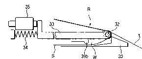
Fig. 1 be the sidewall of the front side of label applicator of the present invention is taken away and shown in lateral plan;
Fig. 2 A and Fig. 2 B are used for the enlarged drawing of turning part in the instruction diagram 1;
Fig. 3 is the amplification plan view that bottom leading section in the label applicator after the cover plate part is taken in expression away;
Fig. 4 is the amplification stereogram of the bottom leading section behind the installation cover plate in the presentation graphs 3;
Fig. 5 sees the stickup cylinder of label applicator and the amplification stereogram behind the label check-out console from oblique below;
Fig. 6 is an instruction diagram of roughly representing the control circuit of label applicator.
The optimal morphology that carries out an invention
Below, describe an embodiment of label applicator of the present invention with reference to the accompanying drawings in detail.
In Fig. 1, Fig. 2 A and Fig. 2 B, continous label R is, the label L that prints is many continuously and be bonded on the base stock S temporarily, and package becomes the cylinder shape.Label applicator 10 comprises: body 20; On body 20, be fulcrum and the bottom 30 that can open and close with take-up roller axle described later.
As the label retainer 31 of the label filling department of placing continous label R, have the paper dorsal part be bearing in by single armed under the opened state on the bottom 30, a part makes the elastic portion 31a on the paper tube P of rubbing effect at continous label R.
The two ends of the king pin 32 that the transfer direction of base stock S among the continous label R is changed are rotatably installed on the pin supporting member 33, and this supporting member 33 can be configured on the bottom 30 to displacement by left and right directions (transfer direction of label/base stock) in Fig. 1, Fig. 2 A and Fig. 2 B.
As shown in Figure 3, the concrete variable bit structure of pin supporting member 33 is, make top be equipped with that the vertical excellent 33a of the portion running-fit of this supporting member 33 of the T word shape of king pin 32 forming on the bottom 30 by the rib 30a shown in a part of hatching between, in Fig. 4, this running-fit part is covered by cover plate 30b.
In addition, shown in Fig. 2 A, pin supporting member 33 is compressed spring 34 right-hand application of force in figure on bottom 30, when base stock S is loosening, to right-hand displacement, removes the operation with the micro-switch 35 of left end adjacency, thereby makes the on/off state exchange of switch.
Fig. 3 specifically represents micro-switch 35, since with the end of the vertical excellent 33a of portion in the pin supporting member 33 be oppositely arranged be operated member (pin rod) because of internal mechanism be subjected to desire from Switch main body to the outstanding application of force in outside, so the compression spring 34 shown in Fig. 2 A and Fig. 2 B not necessarily needs.
Take-up roller 36 be journaled into can open and close bottom 30 is installed on the axle 36a on the body 20, and be connected with the DC motor 21 that is configured in body 20 sides, and be subjected to suppressing by pressing roller 37 by speed reduction gearing 22.
In addition, as shown in Figure 4, disposing by the combination of rack and pinion on bottom 30 links mutually produce near or away from front tag width director 40, and a pair of hook 30c that takes off with overlap joint pin described later system that is formed with body 20 sides.
Because guide wheel 39a is located at body 20 sides, and guiding protuberance 39b and guide wheel 39c are located at bottom 30 sides, so help being used for transferring continous label R and base stock S.In addition, guiding protuberance 39b is formed on the lower edge of the breach W on the bottom 30 with growing crosswise, with to leading from the base stock S of king pin 32 to guide wheel 39c.
Pasting roller 23 is rotatably installed on the leading section of body 20, under the state that bottom 30 is closed, be in the downstream that the label of king pin 32 of the label temporary support 30d of portion of the front end inner face of crossing this bottom 30 is transferred, printing surface (the mucilage glue surface opposite) side of the label of sending here is peeled off in supporting.In addition, the label temporary support 30d of portion of bottom 30 is made of several ribs that form to the label transfer direction.
Label check-out console 24, be installed in the king pin 32 of the state that bottom 30 closes and paste between the roller 23, promptly, the label peeling that can enter label temporary support portion 30d zone from the printing surface side of label is transferred the front that the rotation of ground, path is installed in body 20 freely, simultaneously, though strength a little less than, also can give rotation elastic force by compression spring 25 to its approach axis, and with the opposition side of transferring the path, can in the light path of penetrating type sensor 26, enter, withdraw from.
Handle 27 be with the upside part of body 20 to the left and right direction shear and form, and set up trigger switch (source switch) 28 at its downside, in addition, portion holds battery within it.
As shown in Figure 5, opening 29 is configured in a pair of structure (diagram only for one-sided) on the two sides of front of body 20, and, both are that rotating fulcrum connects with the upper end, simultaneously, the lower end of swing side connects by overlap joint pin 29a, and this overlap joint pin 29a takes off with the hook 30c of described bottom 30.
Control circuit module CSB is that analog representation is installed in the state on the body 20, comprises circuit substrate and circuit component mounted thereto.
These label applicator 10 beginnings are fulcrum with the axle 36a of take-up roller 36, bottom 30 is roughly opened 90 degree, and on label retainer 31, place continous label R, at this moment, continous label R is placed in the central authorities of this retainer 31 because of the retainer side tag width director 31b of label retainer 31.In addition, the paper tube P of continous label R is owing to be subjected to the friction of the elastic portion 31a of label retainer 31, so continous label R sent the generation drag effect.
Then, make the interval of front tag width director 40 consistent with the width of label L (base stock S), the front that makes on one side continous label R is by this width director 40, on one side around the right outer planet of king pin 32 to, by with the lower edge being the breach W of guiding protuberance 39b.Behind the closed bottom 30, will through guide wheel 39c and the front end of removing the base stock S of label L not inserts take-up roller 36 and by pressing roller 37 between.In addition, when closed bottom 30, the part of the upstream side of seeing from the king pin 32 of continous label R is pressed towards bottom 30 sides by guide wheel 39a, so that the turning efficiency of base stock S improves.
For only from the right periphery system of king pin 32 front around continous label R, shown in Fig. 2 A, because base stock S floats and is not tightened on the continous label R from guiding protuberance 39b, so pin supporting member 33 spring 34 is by compression pushed and to right-hand displacement, remove pushing of micro-switch 35, make it to be in the lax state that detects of base stock.
Therefore, when connecting trigger switch 28, in the control circuit of Fig. 6 when the handle 27 of holding body 20, the lax testing circuit 50 of base stock is output (L level) base stock unbracking signal just, its result, the door of opening NAD gate circuit 80 makes transistor 90 conductings, thereby drives DC motor 21.
Its result, take-up roller 36 be by speed reduction gearing 22 and to right-hand revolution, press pressing roller 37 and follow to anticlockwise direction with it and rotate, and drawn thereby the front end of base stock S sandwiches between two rollers.
Because continous label R is subjected to the friction drag of the elastic portion 31a of label retainer 31 relative paper tube P, so base stock S tightens by being pulled, its result, label L on the base stock S that turns to king pin 32 is stripped from (tag state is arranged) because of self rigidity, and shown in Fig. 2 B, when base stock S is crimped on that guiding protuberance 39b goes up and when further tightening, pin supporting member 33 overcomes the tension force (situation to the rod of the pin in the micro-switch 35 application of force is only also arranged) of compression spring 34 and to the left displacement, and pushes micro-switch 35.
By pushing micro-switch 35, the lax testing circuit 50 of base stock converts base stock to and tightens the output state of signal (H level), and the door that makes NAD gate circuit 80 is closed and transistor 90 is opened circuit, thereby DC motor 21 is quit work.
Therefore,, peel off a certain amount ofly, make the printing surface side via the label temporary support 30d of portion and to paste roller 23 relative, expose opposite mucilage glue surface side with the relative label L of base stock S that carries out knuckle section by king pin 32.
Stick on occasion on the article (thing is stuck) at the label L that will expose mucilage glue surface, make trigger switch 28 keep connecting on one side, hold the handle 27 of body 20 on one side, and by pasting roller 23 with label L by being pressed on the article, then, if label applicator 10 integral body are pulled to the direction (left) opposite with the transport direction of label L, then label L just is secured on the article.
When the mucilage glue surface of label L by be pressed on the article, during label applicator 10 integral body the are pulled to direction opposite with the transport direction of label L, label L is secured on the article with regard to relatively sending from label applicator 10 successively, and, this label L to fully from base stock S peel off during (stick on the base stock S during) temporarily, shown in Fig. 2 A, base stock S produces lax along with sending of label L, to leave king pin 32.When being in the such state of Fig. 2 A, identical during with aforesaid initial placement, drive DC motor 21, and with take-up roller 36 with press the base stock S that pressing roller 37 draws after relaxing, thereby get back to the state of Fig. 2 B, stop DC motor 21.In addition, when in advance base stock S being relaxed along with label L, base stock S just enters between article and the label L, suitably adhesive label.
Like this, when base stock S is lax, just drive DC motor 21 and draw base stock S, stop in case base stock S just tightens, this repeatedly action that traction base stock S is ended, draw base stock S, and when sticking on label L on the article, just facilitate label L must leave the action of base stock S.
And, peel off from base stock S fully as label L and stick on the article and when leaving label applicator 10, since theretofore with peel off the way in the printing surface side of label L slide the label check-out console 24 contact because of the tension force of compression spring 25 to clockwise direction rotation specified amount and from the light path of penetrating type sensor 26, do to keep out of the way, the label that former state with penetrating type sensor 26 is a signal has or not testing circuit 60 to convert the output state (L level) of no label to, closed of door that does not make NAD gate circuit 80 is turn-on transistor 90 still, and continues to drive DC motor 21.
By the traction that drives by the signal that has or not testing circuit 60 from label that DC motor 21 produces with the tensioned state be close to the king pin 32 of base stock S, then immediately following after label L peel off because of self rigidity, and advance to pasting roller 23 via the label temporary support 30d of portion always.Owing to peel off mobile label L by this, make label check-out console 24 overcome weak compression spring 25 tension force and by on push away to anticlockwise motion, and the light path that enters penetrating type sensor 26, so label has or not testing circuit 60 to convert the output state (H level) of label to, and triggers timer circuit 70.The timer circuit 70 that is triggered converts output state to specified time T (L level), the door that does not make NAD gate circuit 80 during this period continuing this state is turn-on transistor 90 still closedly, and continue to drive DC motor 21, proceed peeling off of label L.
When timer circuit 70 timings then, always synthesize the H level from the signal of 3 circuit 50,60,70, the door of NAD gate circuit 80 is closed, its result because transistor 90 opens circuit, DC motor 21 quits work, so peeling off of label is stopped.
Label check-out console 24 is pasted roller 23 relatively and is positioned at the upstream side that label is transferred, the effect of timer circuit 70 is, for this machine is in the stickup readiness for action, make immediately following after the leading section of peeling off side of label L below pasting roller 23, in order to change the overburden amount of label L, specified time T can adjust with for example variable resistance.
On the other hand, will paste roller 23 and be divided into 2, and the label check-out console is reached the middle part of pasting roller that do not exist of two rollers, and have or not label as long as can detect near the stickup roller, timer circuit 70 not necessarily needs so.
Because the stickup of label on article is to be undertaken by label applicator 10 and relatively moving of article, so,, article are pressed into from above on the label that exposes mucilage glue surface even in advance label applicator 10 is fixed to opposite top, be put on and paste on the roller, also can paste.In addition, also DC motor 21 sides can be erect fixed labels labelling machine 10 in ground, below, stick on the article with pulling outgoing label L.In addition, be fixing and use label applicator, can in parallel on-state be set as semifixed such for example skate Switch with trigger switch 28 is electric if set in advance, then very convenient.
Below, describe with regard to special example.The king pin 32 that is installed on the pin supporting member 33 can be to label transfer direction (about among the figure) displacement, relatively near or away from the label temporary support 30d of portion, and sometimes and the 30d of this temporary support portion between produce roomy gap.In addition, when the stickup degree of the rigidity weakness of the label that uses, viscose glue is strong, even base stock turns to, label can not be peeled off and be cut off from base stock fully, in case and the condition of the gap enlargement between king pin 32 and the label temporary support 30d of portion coincides, label just can not be shelved on the label temporary support 30d of portion, and encases king pin 32 with base stock, thereby can not be stripped from.
Under the situation of this character label of specific use, make king pin 32 be partial to right-hand and set pin supporting member 33, so that the gap between king pin 32 and the label temporary support 30d of portion is the narrowest and small state.In addition, be fixed to the state that continues to drive DC motor 21 because the downstream direction that meaning king pin 32 deflection labels are transferred is exactly the output of the lax testing circuit 50 of base stock, need with detect that state that base stock tightens is fixing in the same manner to be set as output invalid or this circuit 50 with the lax testing circuit 50 of base stock.
As shown in Figure 3, micro-switch 35 is fixed on the bottom 30 by switch holding plate 41.Therefore, if fixedly being become flexible with micro-switch 35 relative switch holding plates 41, press pad supporting member 33 floatless switch 35 after left displacement limit positions with this switch 35 (pin rod), then the gap between king pin 32 and the label temporary support 30d of portion becomes the narrowest and small, in addition, because so-called is exactly relatively to push micro-switch 35 by this member 33 by pad supporting member 33, the output of testing circuit 50 so base stock relaxes is fixed to detect the state that base stock tightens identical.
In addition, as shown in Figure 5, utilize the board mounting 20A of label sensor 24, compression spring 25 and penetrating type sensor 26, shown in long and two-short dash line, come adapter plate spring 20B like that, owing to this laminated spring 20B is arranged, so after bottom 30 closures, in position near king pin 32, just continous label R is pressed into the inner face of bottom 30, thereby the steering horizontal of base stock S is improved.
Its result, control circuit is, just not saying whether make timer circuit 70 play effect temporarily, only when having or not testing circuit 60 to detect no label, label drives DC motor 21, even it is insufficient that label is peeled off from base stock, can not be shelved on the label temporary support 30d of portion with surrounding yet and advance along king pin 32, and below stickup roller 23, after circuit 60 has detected label, just stop to drive it.
This special example is, because in fact the lax testing circuit 50 of base stock does not produce effect, so label has or not testing circuit 60 not drive DC motor 21 under detecting the state of label (label is peeled off from base stock the way), and owing to can not facilitate to loop property label peeling, so as long as the length of label is not very long, label just can be peeled off from base stock, but no problem ground carries out paste operation at once.
And, if adopt the mechanism of the pin supporting member 33 of above-mentioned micro-switch 35 to fix, then do not change control circuit, just can be suitable for this special example.
The possibility of industrial utilization
As mentioned above, label applicator of the present invention can be continuously and easily exists the label sticking of ormal weight On the article, and it is not only light weight but also firm, therefore, is very useful in the practicality.
Claims (3)
1. a label applicator is characterized in that, comprising: at transport direction effect resistance and the label that prints is many continuously and be bonded in the label filling department that barrel-contoured continous label is kept that rolls on the base stock temporarily; The base stock that makes the continous label of sending from the label filling department turns to, utilizes the label self rigidity and facilitates it from turning part that base stock is peeled off; With electrical motor that the base stock after turning to is drawn reeling end as drive source; Be positioned at the label paste section of swivel of the printing surface side of the label after peeling off from base stock; The label that detects that has or not to the label after peeling off from base stock has or not detecting device; By the label paste section with the released part of label by be pressed on the thing that is stuck and when sticking on label on the thing that is stuck or when pulling outgoing label when the label-side and the thing that is stuck are relatively moved to the interrupted lax base stock that detects of the base stock that produced along with label sending during peeling off from the base stock fully detecting device that relaxes; Also make electric motor driven control circuit when driving motor and the detection that has or not detecting device to produce no label by base stock reeling end traction base stock and when label are exported when the lax detecting device of base stock produces the lax detection output of base stock; And, even the timer circuit that the detection output state that label has or not detecting device to convert label to also can continue driving motor and can be adjusted the time of this continuation.
2. label applicator as claimed in claim 1, it is characterized in that, the turning part remains on the end of turning part supporting member, and is configured to be subjected to the application of force and whole variable bit, carries out this displacement and send the unbracking signal that the lax detecting device of base stock is used when base stock is lax.
3. label applicator as claimed in claim 2, it is characterized in that, in the label temporary support portion that configuration between turning part and the label paste section is supported the label after peeling off owing to turning to of base stock and from base stock, this turning part deflection is fixed under the state of the label temporary support portion side of displacement direction, and the output of the lax detecting device of base stock is being fixed into the anti-lax output state that detects.
Applications Claiming Priority (6)
| Application Number | Priority Date | Filing Date | Title |
|---|---|---|---|
| JP80131/98 | 1998-02-20 | ||
| JP8013198 | 1998-02-20 | ||
| JP80131/1998 | 1998-02-20 | ||
| JP29600098A JP4155476B2 (en) | 1998-02-20 | 1998-09-10 | Label sticking machine |
| JP296000/1998 | 1998-09-10 | ||
| JP296000/98 | 1998-09-10 |
Publications (2)
| Publication Number | Publication Date |
|---|---|
| CN1272088A CN1272088A (en) | 2000-11-01 |
| CN1089707C true CN1089707C (en) | 2002-08-28 |
Family
ID=26421190
Family Applications (1)
| Application Number | Title | Priority Date | Filing Date |
|---|---|---|---|
| CN99800818A Expired - Fee Related CN1089707C (en) | 1998-02-20 | 1999-01-20 | Labeling machine |
Country Status (11)
| Country | Link |
|---|---|
| US (1) | US6328086B1 (en) |
| EP (1) | EP1060994B1 (en) |
| JP (1) | JP4155476B2 (en) |
| KR (1) | KR100416666B1 (en) |
| CN (1) | CN1089707C (en) |
| DE (1) | DE69933366T2 (en) |
| HK (1) | HK1030587A1 (en) |
| MY (1) | MY124590A (en) |
| PL (1) | PL195517B1 (en) |
| TW (1) | TW407124B (en) |
| WO (1) | WO1999042372A1 (en) |
Families Citing this family (18)
| Publication number | Priority date | Publication date | Assignee | Title |
|---|---|---|---|---|
| NL1018446C2 (en) * | 2001-07-03 | 2003-01-08 | Sergius Arnoldus Jo Broekhoven | Handheld tool for applying adhesive labels to packages, has motor which draws backing paper past delivery point when sensor detects contact with package surface |
| WO2005009750A1 (en) * | 2003-07-29 | 2005-02-03 | Fofitec Ag | Dispenser material for production of objects with bonded cards, production method and use thereof |
| US20050279463A1 (en) * | 2004-06-21 | 2005-12-22 | Ridenour Guy K | Apparatus for dispensing labels to an operator without delay |
| US7108154B1 (en) | 2004-08-11 | 2006-09-19 | Dennis Thompson | Kick on shoe covers |
| CN100449589C (en) * | 2005-07-06 | 2009-01-07 | 上海寺冈电子有限公司 | Tagboard and device for printing same |
| KR100751821B1 (en) * | 2006-08-10 | 2007-08-29 | 엄현덕 | Staple safety plate and stapler with auto feeder |
| KR100791893B1 (en) | 2006-10-25 | 2008-01-07 | 엄현덕 | A staple index sticker structure and an index sticker with stapler |
| JP2010070211A (en) * | 2008-09-18 | 2010-04-02 | Towa Seiko Kk | Hand labeler |
| JP6323637B2 (en) * | 2013-05-24 | 2018-05-16 | ブラザー工業株式会社 | Printing device |
| JP2016005961A (en) * | 2014-06-20 | 2016-01-14 | セイコーエプソン株式会社 | Label peel device, ink jet recording device and label peel method |
| CN105314193B (en) * | 2014-06-19 | 2018-09-04 | 精工爱普生株式会社 | Label stripping apparatus, liquid discharge device and label stripping means |
| CN104369933B (en) * | 2014-11-11 | 2016-06-15 | 东莞市钜大电子有限公司 | A kind of hand-held applicator |
| TWI551516B (en) * | 2015-02-05 | 2016-10-01 | 緯和有限公司 | Storage sealer |
| JP1608027S (en) * | 2017-10-17 | 2018-07-02 | ||
| JP7064868B2 (en) * | 2017-12-26 | 2022-05-11 | リンテック株式会社 | Sheet supply device and sheet supply method, and sheet pasting device and sheet pasting method |
| CN109110239A (en) * | 2018-09-25 | 2019-01-01 | 广州超音速自动化科技股份有限公司 | labelling machine |
| TR201910104A2 (en) * | 2019-07-05 | 2019-07-22 | Abdulgadir Yilmaz | LABELING MACHINE WITH MODULAR BLOCK UNIT |
| ES2915586B2 (en) * | 2020-12-22 | 2023-02-14 | Fundacion Para La Promocion De La Innovacion Investig Y Desarrollo Tecnologico En La Industria De Au | Automatic sticker dispensing system |
Citations (3)
| Publication number | Priority date | Publication date | Assignee | Title |
|---|---|---|---|---|
| JPH0113052Y2 (en) * | 1984-08-30 | 1989-04-17 | ||
| JPH0132532B2 (en) * | 1983-09-05 | 1989-07-05 | Matsushita Electric Ind Co Ltd | |
| JPH03212336A (en) * | 1989-12-29 | 1991-09-17 | Brother Ind Ltd | Label printer |
Family Cites Families (11)
| Publication number | Priority date | Publication date | Assignee | Title |
|---|---|---|---|---|
| US3403066A (en) * | 1964-07-15 | 1968-09-24 | Gerald S. Ikelheimer | Label or tape dispenser and applicator |
| JPS509560B1 (en) * | 1970-01-31 | 1975-04-14 | ||
| JPS5212080B2 (en) * | 1972-10-05 | 1977-04-04 | ||
| JPH0742247B2 (en) | 1987-07-06 | 1995-05-10 | 日本石油化学株式会社 | Method for producing [(1-phenylethenyl) phenyl] propionic acid and / or ester thereof |
| JPH0832532B2 (en) * | 1990-04-28 | 1996-03-29 | 大阪シーリング印刷株式会社 | Cartridge type label dispenser |
| US5254206A (en) * | 1992-01-31 | 1993-10-19 | Wing Donald B | Hand-held labeling device |
| JP2708680B2 (en) | 1992-09-14 | 1998-02-04 | 東和精工株式会社 | Label sticking machine |
| US5516398A (en) * | 1992-10-08 | 1996-05-14 | Kabushiki Kaisha Sato | Excessive label projection prevention device for labeler |
| US5525184A (en) * | 1993-01-04 | 1996-06-11 | Monarch Marking Systems, Inc. | Label dispenser with selectable dispense modes including an on-demand mode |
| JPH0832532A (en) | 1994-07-20 | 1996-02-02 | Nec Eng Ltd | Voice moving order device and fire fighting order device provided with it |
| US5779852A (en) * | 1996-06-11 | 1998-07-14 | Sensormatic Electronics Corporation | Handheld applicator |
-
1998
- 1998-09-10 JP JP29600098A patent/JP4155476B2/en not_active Expired - Fee Related
-
1999
- 1999-01-20 WO PCT/JP1999/000173 patent/WO1999042372A1/en active IP Right Grant
- 1999-01-20 EP EP99900641A patent/EP1060994B1/en not_active Expired - Lifetime
- 1999-01-20 KR KR10-2000-7000699A patent/KR100416666B1/en not_active IP Right Cessation
- 1999-01-20 US US09/486,907 patent/US6328086B1/en not_active Expired - Fee Related
- 1999-01-20 PL PL342348A patent/PL195517B1/en not_active IP Right Cessation
- 1999-01-20 CN CN99800818A patent/CN1089707C/en not_active Expired - Fee Related
- 1999-01-20 DE DE69933366T patent/DE69933366T2/en not_active Expired - Lifetime
- 1999-02-06 TW TW088101825A patent/TW407124B/en not_active IP Right Cessation
- 1999-02-09 MY MYPI99000440A patent/MY124590A/en unknown
-
2001
- 2001-02-28 HK HK01101447A patent/HK1030587A1/en not_active IP Right Cessation
Patent Citations (3)
| Publication number | Priority date | Publication date | Assignee | Title |
|---|---|---|---|---|
| JPH0132532B2 (en) * | 1983-09-05 | 1989-07-05 | Matsushita Electric Ind Co Ltd | |
| JPH0113052Y2 (en) * | 1984-08-30 | 1989-04-17 | ||
| JPH03212336A (en) * | 1989-12-29 | 1991-09-17 | Brother Ind Ltd | Label printer |
Also Published As
| Publication number | Publication date |
|---|---|
| EP1060994A1 (en) | 2000-12-20 |
| CN1272088A (en) | 2000-11-01 |
| EP1060994A4 (en) | 2004-05-19 |
| JPH11301629A (en) | 1999-11-02 |
| DE69933366D1 (en) | 2006-11-09 |
| PL195517B1 (en) | 2007-09-28 |
| WO1999042372A1 (en) | 1999-08-26 |
| US6328086B1 (en) | 2001-12-11 |
| KR100416666B1 (en) | 2004-01-31 |
| DE69933366T2 (en) | 2007-08-09 |
| EP1060994B1 (en) | 2006-09-27 |
| PL342348A1 (en) | 2001-06-04 |
| MY124590A (en) | 2006-06-30 |
| TW407124B (en) | 2000-10-01 |
| HK1030587A1 (en) | 2001-05-11 |
| KR20010022129A (en) | 2001-03-15 |
| JP4155476B2 (en) | 2008-09-24 |
Similar Documents
| Publication | Publication Date | Title |
|---|---|---|
| CN1089707C (en) | Labeling machine | |
| KR101660097B1 (en) | Labeling device | |
| JP4127903B2 (en) | Labeling device | |
| JP4791174B2 (en) | Label sticking device and label sticking method | |
| JP2010023964A (en) | Winding method and winding device of label mount | |
| JP4848129B2 (en) | Labeling device | |
| JP5175514B2 (en) | Labeling device | |
| CN2512605Y (en) | Thermal sensitive label printer | |
| JP3173206B2 (en) | Tape feeder | |
| CN109436495A (en) | A kind of label bilayer feeding device | |
| JPS61229717A (en) | Feeder for taping part | |
| KR102383306B1 (en) | Labeling machine | |
| CN114789837A (en) | COB optical module processing assembly | |
| CN109625519B (en) | Automatic labeling machine head and working method thereof | |
| CN209410569U (en) | Label bilayer feeding device | |
| JP4167327B2 (en) | Labeling device | |
| JP5951276B2 (en) | Labeling device | |
| JPS629208Y2 (en) | ||
| CN112644787B (en) | Packing plant and cooking equipment | |
| CN211000379U (en) | Online dyestripping mechanism | |
| JPH01233789A (en) | Method and equipment for sticking film | |
| JPH10203518A (en) | Label detaching apparatus | |
| JP2006082812A (en) | Label peeling method, label peeling device, and label affixing device | |
| JP2001180629A (en) | Suction body for label pasting device | |
| JP2004315027A (en) | Label affixing device |
Legal Events
| Date | Code | Title | Description |
|---|---|---|---|
| C06 | Publication | ||
| PB01 | Publication | ||
| C10 | Entry into substantive examination | ||
| SE01 | Entry into force of request for substantive examination | ||
| C14 | Grant of patent or utility model | ||
| GR01 | Patent grant | ||
| C17 | Cessation of patent right | ||
| CF01 | Termination of patent right due to non-payment of annual fee |
Granted publication date: 20020828 Termination date: 20100220 |