EP0110792B1 - Control arrangement for data processing system employing multiple processors - Google Patents
Control arrangement for data processing system employing multiple processors Download PDFInfo
- Publication number
- EP0110792B1 EP0110792B1 EP83402327A EP83402327A EP0110792B1 EP 0110792 B1 EP0110792 B1 EP 0110792B1 EP 83402327 A EP83402327 A EP 83402327A EP 83402327 A EP83402327 A EP 83402327A EP 0110792 B1 EP0110792 B1 EP 0110792B1
- Authority
- EP
- European Patent Office
- Prior art keywords
- control block
- queue
- pointer
- work queue
- station
- Prior art date
- Legal status (The legal status is an assumption and is not a legal conclusion. Google has not performed a legal analysis and makes no representation as to the accuracy of the status listed.)
- Expired
Links
Images


Classifications
-
- G—PHYSICS
- G06—COMPUTING; CALCULATING OR COUNTING
- G06F—ELECTRIC DIGITAL DATA PROCESSING
- G06F9/00—Arrangements for program control, e.g. control units
- G06F9/06—Arrangements for program control, e.g. control units using stored programs, i.e. using an internal store of processing equipment to receive or retain programs
- G06F9/46—Multiprogramming arrangements
- G06F9/48—Program initiating; Program switching, e.g. by interrupt
- G06F9/4806—Task transfer initiation or dispatching
- G06F9/4843—Task transfer initiation or dispatching by program, e.g. task dispatcher, supervisor, operating system
- G06F9/4881—Scheduling strategies for dispatcher, e.g. round robin, multi-level priority queues
-
- G—PHYSICS
- G06—COMPUTING; CALCULATING OR COUNTING
- G06F—ELECTRIC DIGITAL DATA PROCESSING
- G06F15/00—Digital computers in general; Data processing equipment in general
- G06F15/16—Combinations of two or more digital computers each having at least an arithmetic unit, a program unit and a register, e.g. for a simultaneous processing of several programs
- G06F15/161—Computing infrastructure, e.g. computer clusters, blade chassis or hardware partitioning
Definitions
- the invention relates generally to the field of arrangements in which data processing systems employing multiple special-purpose processors control or schedule the processing of tasks or processes, and more particularly to arrangements by which instructions for processing tasks or processes are transferred among the processors forming such a multi-processing system.
- processors used in electronic data processing systems over the last few years have given rise to a dramatic increase in the number of processors, particularly microprocessors, that are used in data processing systems.
- processors are used in data processing systems both as part of processor units for processing user programs and as part of control units that control many of the peripheral storage elements such as disk and tape drives and input/ output elements such as printers, keyboards and visual display devices, scientific instruments, card readers and punches, communications lines and the like.
- processor units it is desirable to use separate processor units in a system to execute various classes of instructions.
- many systems have separate processor units constructed to execute floating point instructions of fixed point instructions or to perform matrix operations or operate on or search strings of characters.
- Special processor units are designed to speed execution of these instructions.
- the separate processor units may be able to execute instructions simultaneously, thereby speeding operation of the system.
- processors in peripheral and input/ output control units allows a processor unit to use high-level commands to the control units that only generally defines the operations to be performed, and the control unit itself then determines the detailed operations that must be performed to carry out the operations required by the commands.
- processors in the control unit can initiate and perform diagnostics or maintenance on the attached peripheral units without intervention of the processing unit or units, thereby freeing them to concentrate on executing user programs. This arrangement substantially lessens the amount of direct attention that a processor unit must give to the detailed operations of the peripheral and input/output elements.
- a master processor generates tasks required by a user program, for example, and distributes them to the slave processors.
- the master processor generally monitors the status of the slave processors. To initiate an operation by the slave processor, the master interrupts the slave, and when the slave processor finishes the task, it interrupts the master processor to indicate status. The master processor may then assign the slave a new task.
- the master processor may also perform diagnostics and maintenance programs on the system.
- master processor simplifies scheduling, but if the demands on the master processor are heavy, it may become overloaded, thereby slowing down the system. Furthermore, the requirement that the master and slave processors communicate by interrupts further adds to the overhead, as time is required for both processors to service the interrupts.
- the second arrangement eliminates the necessity of dedicating a processor solely to generating tasks and scheduling.
- a state list of processes and their status are stored so as to allow any processr to have access to the list.
- a processor Whenever a processor must stop execution of a process, it updates the process's status in the state list and then finds another process to run.
- it is necessary to establish good coordination and communication among all of the processors to ensure that a process is being processed by only one processor at a time, and also to ensure that all processes are processed. As the number of processors in the system increases, satisfactory communication and coordination becomes more difficult to achieve.
- a system employs multiple special-purpose processors to execute a plurality of commands.
- each command is processed by performing a pre-defined sequence of operations.
- Each operation is performed by a processor, or more specifically by a process, or "station”, that is executed by one of the processors in the system.
- a memory unit in the system stores a "route” which contains a list of "route vectors” each specifying an operation to be performed to execute the command and the station which is to perform the operation.
- a command is received, one processor, as a source processor, generates a control block from the host command.
- the control block includes a pointer identifying first route vector in the route and transfers the control block to a work queue of the station which is to perform the first operation.
- Each station sequentially retrieves control blocks from its work queue. After retrieving a control block, the station retrieves the route vector specified by the route vector. After performing the operation, the station advances the pointer in the control block to identify the next route vector in the route and transfers the control block directly to the work queue of the station identified in the next route vector as performing the next operation.
- each route vector may also include an identification of a station to receive a control block if the executing station is unsuccessful in its attempt to perform the operation required by the route vector.
- each processor may process a plurality of stations, with each station having a separate work queue.
- each processor also can have a service queue.
- the identification of the work queue is also transferred to the receiving processor's service queue.
- a processor can determine from its service queue that one of its stations' previously-empty work queues now has a control block. The processor thus need not poll its station's work queues to determine whether they contain control blocks to be processed, and a transferring station need not interrupt a processor of a receiving station when it is transferring a control block to an empty work queue.
- the source processor may generate multiple independently-executable control blocks from certain host commands. If multiple control blocks are generated, the source processor may also establish a counter identifying the number of control blocks that it generated based on the command. When a station executes the last route vector in the route for a control block, it decrements the counter. When the counter is decremented to zero, a response is generated indicating that the command has been executed.
- Fig. 1 depicts a peripheral controller 10 having a multiprocessing arrangement, including four special-purpose processors, including a host interface controller processor 12, a disk controller processor 14, a tape controller processor 16, and a source processor 18.
- the host interface controller processor 12 communicates with a host data processing system (not shown) over a host bus 20 and transfers commands and status information between the host bus 20 and a control memory 22 over a control information bus 24.
- the host interface controller processor 12 also transfers data between the host bus 20 and a data memory 26 over a data bus 28.
- the disk controller processor 14 and tape controller processor 16 are also connected to control information bus 24 and data bus 28.
- Disk controller processor 14 is also connected to a plurality of disk drives, four of which are shown in Fig. 1, generally indicated at 30, and tape controller processor 16 is also connected to tape drives, four of which are shown in Fig. 1, generally indicated at 32.
- Control memory 22 also stores control information that is used by disk controller processor 14 and tape controller processor 16 to transfer data stored in data memory 26 between disk drives 30 any/or tape drives 32 over data bus 28.
- the control memory also stores control information that is used by host interface controller processor 12 in performing its operation.
- the source processor 18 is also connected to control information bus 24 and data bus 28 and may retrieve control information from and store control information in control memory 22.
- Source processor 18 generates the control information that is used by the disk controller processor and tape controller processor, and may also execute diagnostic and maintenance programs.
- the peripheral controller 10 depicted in Fig. 1 is shown as being connected only to disk drives 30 and tape drives 32. This is by way of example only; the peripheral controller can also be connected to other types of peripheral devices as well as to input/output devices such as printers, video display terminals and keyboards, scientific devices and instruments, and to communication lines, with suitable controller processors. Furthermore, the controller 10 may be connected to several host processors through additional host interface controller processors 12.
- the source processor 18 is also connected to control information bus 24 and data bus 28.
- a separate source processor is not required to achieve the benefits of the invention; one or more of the controller processors 12, 14 and 16 may perform the functions of the source processor.
- the source processor 18 retrieves the host commands that are loaded into control memory 22 and generates the control information that the processors 12, 14 and 16 use to execute the host commands. Additionally, the source processor 18 processes maintenance or diagnostic programs to insure that the controller 10 is properly operating and to detect the causes of errors that it or that one of the other processors may detect.
- either source processor 18 or the controller processors 14 and 16 may perform certain operations such as generating the usual sector or'block identification information that may be written as a header on disks or tapes during WRITE operations or other transfers in which data is transferred to the peripheral or input/output unit. These operations are performed by tasks or processes forming a part of the respective processor's control programs. Each task or process that is performed by the processors 12, 14, 16 and 18, in response to a host command, including diagnostic and maintenance tasks that may be initiated by the source processor 18, is a "station".
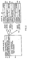
- each host command that can be executed by peripheral controller 10 is associated with a route 36, an example of which is depicted to the right in Fig. 2.
- the routes are stored in control memory 22 and thus may be used by any of the stations forming the peripheral controller.
- Each route vector 38 in the list identifies, in an OPCODE field 39, an operation to be performed during processing of the host command.
- Each route vector 38 also identifies the station to execute the route vector, that is, to perform the operation identified in the OPCODE field 39 of the route vector, in the list in a STATION field 40.
- each route vector 38 also contains fields which identify the station to be notified if a station is unsuccessful in its attempt to perform the operation required by the route vector 38, in an ERROR DESTINATION field 41, and four lags, an X flag 42, an H flag 43, an E flag 44, and a B flag 45, which have meanings as described below.
- Control block 49 For each host command that is received by peripheral controller 10, the source processor 18 generates a control block 49, and example of which is depicted to the left Fig. 2.
- Control block 49 includes a current route vector pointer 50 that points to a route vector 38 in the route associated with that host command. More specifically, the current route vector pointer 50 contains the address of the OPCODE field of the first route vector of the route associated with the host command.
- the current route vector pointer 50 of control block 49 points to the first route vector, identified as ROUTE VECTOR (1st OPN), in the route 36.
- the control block 49 also includes a queue link pointer 52, which is the first field of the control block.
- Each station has an associated work queue 58 depicted in Fig. 3.
- the work queue 58 stores control blocks that are processed by the station in the order in which they are stored in the queue.
- the work queue is located in control memory 22 and is defined by (a) a head pointer 60 which points to, or contains the address of the location in control memory 22 containing, the first control block in the station's work queue 58, and (b) a tail pointer 61 that points to, or contains the address of the location in control memory 22 containing, the last control block in the work queue 58.
- the queue link pointer 52 of each control block in the work queue points to the next control block in the queue, thereby identifying the control blocks forming the queue.
- the control block also includes a host command pointer 51, which contains the address of the host command that caused the source processor 18 to generate the control block.
- a host command may cause the source processor 18 to generate multiple control blocks. If this occurs, the source processor may also establish a counter identifying the number of control blocks that are generated for the host command.
- the station that executes the last route vector may decrement the counter using the host command pointer to identify the host command and counter.
- the control block 49 may also contain other information, in fields generally indicated at 53, which is useful in executing the host command. This information may include peripheral or input/ output unit address information, information identifying buffers in data memory 26 containing data to be written or into which data is to be transferred, or the like.
- the source processor 18 when the source processor 18 generates the control block 49 depicted in Fig. 2, it transfers the control block to the work queue 59 (Fig. 3) of the station identified in the first route vector 38 as the station that is to process the first route vector 38.
- Each station sequentially retrieves the control blocks from its work queue 59, and performs the operation called for in the OPCODE field 39 of the route vector 38 to which the current route vector pointer 50 points. If the station is able to perform the operation, it advances the current route vector pointer 50 in the control block to point to the next route vector in route 36. That is, the station loads the address of the next route vector's OPCODE field into the current route vector pointer 50, and performs a SEND operation to transfer the control block to the work queue of the station identified in the STATION field 40 of the route vector 38 now identified by the current route vector pointer 50.
- the station If the station is unable to process the route vector, that is, if it is unable to perform the operation required by the OPCODE field 39, it does not advance the current route vector pointer 50, but instead it uses the SEND operation to transfer the control block to the work queue identified by the ERROR DESTINATION field 41 of the route vector 38, which may be the work queue of a station that executes diagnostic or maintenance programs.
- the invention provides a multiprocessor system having a number of advantages. Since the invention does not require a master processor, delays will not occur due to overloading of any one processor. Indeed, any or all of the processors may operate as source processors to generate control blocks for the system. Further, the stations can transfer the control blocks among the work queues without having to interrupt the receiving station or its associated processor, which also avoids delay. Additionally, the routes allow for a substantial amount of flexibility, such as branching and loops, since the operation and the identity of the station to perform each operation is stored in the route vector itself. This can be useful if the operations to be performed in response to a host command depend on certain conditions. For example, if a disk drive 30 (Fig. 1) has a cache, the operations performed, and hence the route vectors that are processed may depend on whether or not the data to be written onto the disk has already been stored in the cache.
- the invention may be more fully understood by referring to the flow diagram depicted in Fig. 4.
- the host interface controller processor 12 first receives a host command and loads it into the control memory (step 100).
- the source processor 18 retrieves the host command from the control memory 22 and generates one or more control blocks 49 (Fig. 2). If more than one control block is generated for the host command, the control processor may establish a counter indicating the number of control blocks that were generated.
- the source processor 18 From the host command, the source processor 18 generates the control block 49, and transfers it to the work queue (Fig. 3) of the station identified in the STATION field 40 of the first route vector of the route associated with the host command (step 104).
- the process by which one specific embodiment of the invention transfers control blocks will be explained below with respect to Figs. 5, 5A, 6, 6 A and 7 .
- Each station retrieves control blocks from its work queue (step 106). With reference to Fig. 3, in one specific embodiment the station retrieves the control block from the location in control memory 22 identified by the contents of head pointer 60. The station then retrieves the route vector from the location in control memory 22 identified in the current route vector pointer 50 of the control block and performs the operation defined in the OPCODE field (step 108). After performing the operation, the station advances the current route vector pointer 50 (step 110, see also step 126 of Fig. 5). In one specific embodiment, the route vectors are all of uniform length, and the stations need only increment the current route vector pointer 50 by a constant to point to the next route vector. However, the route vectors can be of different lengths, and the sequences that each station uses to process the different route vectors would have to accommodate the different lengths.
- the station After the station advances the current route vector pointer 50, it transfers the control block to another work queue (step 110). If the station successfully perform the operation called for by the route vector, it transfers the control block to the station, specifically the work queue 59 of the station, that is identified by the STATION field 40 of the next route vector in the route. If the station is unable to perform the operation, it transfers the control block to the queue identified in the ERROR DESTINATION field 41 of this route vector. If this is the last route vector of the route 36, the station may also decrement a counter associated with the host command.
- the head pointer 60 of work queue 59 also indicates whether a control block is in the work queue. In one specific embodiment, if the contents of the head pointer are zero, the work queue contains no control blocks to be processed.
- the station tests its work queue head pointer 60 to determine if the work queue is empty (step 112). If the work queue is not empty, the station returns to step 106 and retrieves the next control block from its work queue. If, on the other hand, the head pointer 60 indicates that the work queue is empty, the station may continue to test its work queue head pointer until it is not empty (step 114), at which time it returns to step 106 to process the next control block.
- the routes and route vectors are in a read-only portion of the common control memory 22.
- the route vectors may be distributed among local memories for the stations and processors; if this is the case, each local memory need only store the route vectors required to be executed by the station as well as the next route vector, or at least the STATION field of the next route vector, to allow the station to transfer the control block to the next station.
- This arrangement may require more memory distributed among the stations in which to store all of the route vectors, but it decreases contentions among the stations for the common memory.
- Figs. 5 and 5A depict a sequence that is used by one specific embodiment of a station to transfer control blocks from its work queue to another work queue after it has completed executing the operation specified by the route vector's OPCODE field 39.
- the station first retrieves the address of the current route vector; that is, it retrieves the contents of the current route vector pointer 50 of the control block 49 (step 120). If the station was unable to perform the operation required by the route vector (step 121), it uses the SEND sequence depicted in Fig. 6 to transfer the control block to the work queue identified by the ERROR DESTINATION field 41 of the route vector (step 124). If the station did complete the operation specified by the route vector 38, it advances the current route vector pointer field 50 of the control block 49 to point to the next route vector 38 in the route 36.
- the station then tests the X flag 42, H flag 43, E flag 44 and B flag 45 (Fig. 2) in the route vector 38. If the X flag is not set (step 128), the station decrements any counters that may have been associated with the transfer (step 130). In one specific embodiment, in which a station controls a disk drive, such counters can be used to determine if a SEEK operation is to take place.
- buffers in data memory 26 (Fig. 1) that were reserved for the host command freed so as to be available to other host commands (step 134).
- this route vector is the last route vector in the route.
- a counter associated with the host command the location of which is associated with the host command pointer 51 of the control block, is decremented (step 138).
- the station transfers the control block to the beginning of the work queue of the station to process the next route vector (step 142).
- the control block is transferred to the end of the work queue for the next station (step 144).
- a SEND sequence that is used by one embodiment of a station to transfer a control block to the work queue 59 of another station will be described with respect to Figs. 5, 6A, 7A and 7B.
- the station transfers control blocks by modifying the head pointer 60, tail pointer 61, and queue link pointers 52 (Fig. 2).
- the station first clears the queue link pointer 52 of the control block being sent (step 150).
- the queues are interlocked; that is, if one station is reading from or transferring into the work queue, it loads a value into the head pointer that is recognized by all stations as an interlock value, which locks the queue to prevent any other station from reading from or transferring into the queue while the head pointer 60 contains that value.
- the station tests the contents of the head pointer 60 of the receiving work queue 59 until the contents of the head pointer indicates that the work queue is not locked (step 152).
- the work station then loads the interlock value into the head pointer to lock the queue (step 154).
- the contents of the head pointer are examined to determine if the receiving work queue is empty (step 156). If it is empty, transferring station modifies both the tail pointer 61 and the head pointer 60, in that order, to point to the control block it is transferring. Both pointers are loaded with the address in control memory 22 of the control block being transferred (step 158 and 160). The tail pointer is loaded first (step 158) and the head pointer second, as loading the address into the head pointer also serves to unlock the queue and make it available to other stations.
- step 156 If in step 156 the receiving work queue is not empty, and if the H flag of the route vector was set (Fig. 5A, step 140), a "SEND TO HEAD" sequence is used to transfer the control block to the beginning of the receiving work queue (step 162 and Fig. 7B).
- the contents of the head pointer of the receiving work queue are loaded into the queue link pointer 52 of the control block being transferred (Ctrl BI #0, step 164).
- the queue link pointer of the control block being transferred thus points to the previous first control block in the work queue (Ctr1 B1 #1), as depicted by the broken arrow in Fig. 7B.
- the address of the new first control block (Ctr1 B1 #0) is then loaded into the head pointer 60 (step 166) thereby unlocking the queue.
- step 140 of Fig. 5A If in step 140 of Fig. 5A, the H flag of the route vector was not set, a "SEND" operation is performed depicted in Fig. 7A.
- the transferring station loads the address of the control block being transferred (Ctr1 B1 #N+1) into the queue link pointer 52 of the last control block (Ctr1 B1 #N) in the work queue (step 168).
- the address of the control block being transferred is then loaded into the tail pointer 61 (step 170), and the contents of the head pointer retrieved in step 154 are returned to the head pointer 60 to unlock the queue (step 172).
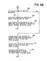
- Fig. 8 depicts a sequence used by a station of one specific embodiment of the invention to retrieve control blocks from its work queue.
- the contents of the queue head pointer 60 is the address of the first control block in the queue.
- the station first tests its work queue head pointer 60 until it indicates that the queue is not locked (step 180).
- the station then retrieves the contents of the head pointer 60 and loads the interlock value into- it to lock the queue (step 181).
- the station tests the retrieved head pointer to determine if the queue is empty (step 182). If the queue is empty, the station restores the head pointer to unlock the queue (step 184).
- the station uses the retrieved head pointer as an address to retrieve the queue link pointer from the first control block in the queue (step 186) and loads the queue link pointer into the queue head pointer to unlock the queue (step 188). The station can then retrieve the control block from the location identified by the retrieved contents of head pointer 60.
- the host command is a SHADOW WRITE operation to an address on disk drive 1 of disk drives 30 (Fig. 1).
- a SHADOW WRITE host command to disk drive 1 causes the data to also be written in disk drives 2 and 3, and a back-up copy of the data to be written on tape drive 4.
- the SHADOW WRITE operation in this example has associated with it a route 36 containing route vectors 38 that cause the peripheral controller to perform the following operations:
- the source processor 18 On receiving this SHADOW WRITE command from the host, the source processor 18 first generates a control block 49 whose current route vector pointer 50 (Fig. 2) points to the first route vector 38 of the route 36 for processing the command. The source processor then transfers the generated control block it to the work queue 59 of the station identified in the STATION field 40 (Fig. 2) of this route vector, in this case the work queue 59 of host interface controller processor 12.
- the host interface controller processor 12 processes control blocks in the order in which they are stored in its work queue. When it gets to the control block for this operation, it retrieves data from the host memory and loads it into the data buffer in the data memory 26 specified in the control block. If it successfully completes this operation, it advances the current route vector pointer 50 to point to the next route vector in the route, and transfers the control block to the work queue of the next station, in this case disk controller 14.
- the disk controller processor 14 also processes the control blocks in the order in which they are stored in the work queue. When it gets to the control block for the SHADOW WRITE operation, it performs the operation required by the second route vector in the route, which causes it to load the data from the buffer specified in the control block in data memory 26 into the location specified in disk drive 1. After it performs this operation, it advances the current route vector pointer 50 to point to the next route vector and transfers the control block to the work queue of the station to process the next route vector, that is, to the station to perform the third operation for the SHADOW WRITE command.
- the station to perform the third operation is also the disk controller processor 14. Therefore, disk controller processor 14 transfers the control block to the end of its work queue.
- the disk controller processor again gets to this control block, it loads the same data from the same buffers in data memory 26 into the disk drive 2. at locations specified in the control block, advances the route vector pointer in the control block, and again transfers the control block to the end of its work queue to cause the data to be loaded into disk drive 3.
- the disk controller processor 14 After the disk controller processor 14 has loaded the data into disk drive 3, it advances the current route vector pointer 50 to point to the next route vector, which causes the generation of the address information to be used as a header for the tape.
- the tape header is generated by a software process, so the disk controller processor 14 sends the control block to the work queue for that software process.
- the software process After the software process generates the tape header, it advances the current route vector pointer 50 to point to the last route vector, and transfers the control block to the work queue of the tape controller processor 16.
- the tape controller processor 16 also retrieves control blocks 49 from its work queue 59 in order. When it gets to this control block, it retrieves the route vector identified by the current route vector pointer 50, which causes it to load the header and the data from the data memory 26 into tape drive 4.
- the tape controller processor 16 may advance the route vector pointer to a subsequent route vector and send the control block back to the work queue of host interface controller processor 12, which may then transmit a response to the host indicating successful completion of the SHADOW WRITE operation.
- the tape controller may indicate to the source processor 18 that the operation has been successfully completed, in which case control processor 18 may generate a response for transmission to the host through host interface controller processor 12.
- any of the stations are unable to perform the operation the operation required by a route vector, instead of transferring the control block to the work queue of the next station, it instead transfers the control block to a station that performs diagnostic or maintenance operations to help determine the cause of the error.
- each processor may handle a plurality of stations, and the source processor 18 may generate a plurality of control blocks 49 from certain host commands.
- each sector of a disk is associated with a different station.
- the data memory 16 is divided into buffers each having enough space to accommodate enough data to fill a disk sector.
- a host command that requires data to be written onto or read from sequential sectors on a disk track may then result in the generation of control blocks 49 which enable the disk controller 14 to, begin transferring data to or from the disk at any sector and retrieving the data from or loading the data into the appropriate buffers in memory 26, eliminating any necessity of waiting until the disk rotates to the first sector before it begins the transfer.
- the source processor 18 (Fig. 1) generates a plurality of control blocks each of which identifies a disk sector involved in the transfer as well as a data buffer in data memory 26 to be used in the transfer, these in field 53 (Fig. 2) of the control block 49, and a route defining the stations and the operations to be performed.
- the source processor then transfers the control blocks to the work queue of the first station in the route for the host command, namely the host interface controller processor 12, which loads data into the buffers in data memory 26 specified in the control blocks.
- the host interface controller processor 12 After the host interface controller processor 12 loads the data into each buffer, it transfers the control block to the work queue of the station to transfer the data from memory 26 to the specified sector on the disk. Since each sector is associated with a separate station, each control block is sent to the work queue of a different station. However, to allow the same route to be used by all of the stations in this transfer, the host interface controller processor 12 would not be able to use the STATION field 40 (Fig. 2) directly to transfer the control blocks, otherwise all of the control blocks would go to the same station. Instead, the host interface controller processor 12 can determine the identity of the station to which it is to send each control block from the STATION field as well as other information in the control block such as the disk sector. In this manner, the same route may be used for sequences in which different stations are to perform the same operation, that is, to execute the same route vector, in the route, to reduce the number of routes that may be required.
- a counter may also be established that indicates the number of control blocks that were generated. In the above example, one control block is generated for each sector to be transferred.
- the station or more specifically the processor that executes the process associated with the station, decrements the counter.
- the processor may generate a response indicating successful completion of the host command.
- a processor When a processor has a plurality of stations, it may poll the stations' work queues to determine if there are control blocks to be processed. If the number of stations becomes large, however, polling the work queues may become time consuming.
- the processor may use a service queue, which is depicted in Fig. 9, which stores an identification of those work queues that were previously empty and into which a station transfers a control block. By polling the service queue, the processor can determine the work queues that have gone from being empty to being not-empty, and thus can determine the stations that require processing.
- each work queue is further defined by a service queue pointer/link 200 and an H flag 202.
- the processor has a service queue also defined by a head pointer 204 and a tail pointer 206.
- the service queue pointer points to, or contains the address in control memory 22 of, the service queue head pointer 204, and the H flag 202 is clear.
- the transferring station also loads an identification of the now not-empty work queue into the service queue.
- the transferring station when the transferring station loads a control block 49 into an empty work queue, it also performs a SEND operation as depicted in Figs. 6, 7A, and 7B on the work queue, specifically altering pointer/ link 200, pointers 204 and 206 and H flag 202.
- the transferring station first clears pointer/link 200 (step 150, Fig. 6). If the service queue was previously empty, the transferring station performs steps 154, 156, 158 and 160 to load the address of the work queue into the service queue head and tail pointers 204 and 206, and also sets the H flag 202.
- the pointer/ link 200 of each work queue in the service queue points to the next work queue in the service queue.
- the transferring station performs steps 162, 168, 170 and 172 to modify the pointer/link 200 of the last work queue in the service queue to point to the new last work queue, and to modify the service queue'tail pointer 206 to also point to the last work queue in the service queue, and additionally sets H flag 202.
- the processor can then perform the sequence depicted in Fig. 8 to determine which previously-empty work queues are not empty, and can retrieve control blocks from the not-empty work queues without having to poll them to determine whether or not they are empty.
Description
- The invention relates generally to the field of arrangements in which data processing systems employing multiple special-purpose processors control or schedule the processing of tasks or processes, and more particularly to arrangements by which instructions for processing tasks or processes are transferred among the processors forming such a multi-processing system.
- The reduction in cost and size of processors used in electronic data processing systems over the last few years has given rise to a dramatic increase in the number of processors, particularly microprocessors, that are used in data processing systems. Processors are used in data processing systems both as part of processor units for processing user programs and as part of control units that control many of the peripheral storage elements such as disk and tape drives and input/ output elements such as printers, keyboards and visual display devices, scientific instruments, card readers and punches, communications lines and the like.
- In many instances, it is desirable to use separate processor units in a system to execute various classes of instructions. For example, many systems have separate processor units constructed to execute floating point instructions of fixed point instructions or to perform matrix operations or operate on or search strings of characters. Special processor units are designed to speed execution of these instructions. Furthermore, in some instances the separate processor units may be able to execute instructions simultaneously, thereby speeding operation of the system.
- The use of processors in peripheral and input/ output control units allows a processor unit to use high-level commands to the control units that only generally defines the operations to be performed, and the control unit itself then determines the detailed operations that must be performed to carry out the operations required by the commands. Furthermore, processors in the control unit can initiate and perform diagnostics or maintenance on the attached peripheral units without intervention of the processing unit or units, thereby freeing them to concentrate on executing user programs. This arrangement substantially lessens the amount of direct attention that a processor unit must give to the detailed operations of the peripheral and input/output elements.
- Systems employing multiple processors generally have one of two types of arrangements for controlling and scheduling the performance of tasks by the various processors. both of which are described in S. Madnick, et al., Operating Systems, (McGraw-Hill Book Company, New York, New York: 1974) at pages 244-247. In one arrangement, a master processor generates tasks required by a user program, for example, and distributes them to the slave processors. The master processor generally monitors the status of the slave processors. To initiate an operation by the slave processor, the master interrupts the slave, and when the slave processor finishes the task, it interrupts the master processor to indicate status. The master processor may then assign the slave a new task. The master processor may also perform diagnostics and maintenance programs on the system.
- The use of a master processor simplifies scheduling, but if the demands on the master processor are heavy, it may become overloaded, thereby slowing down the system. Furthermore, the requirement that the master and slave processors communicate by interrupts further adds to the overhead, as time is required for both processors to service the interrupts.
- The second arrangement eliminates the necessity of dedicating a processor solely to generating tasks and scheduling. In this arrangement, a state list of processes and their status are stored so as to allow any processr to have access to the list. Whenever a processor must stop execution of a process, it updates the process's status in the state list and then finds another process to run. In such a system employing decentralized control, it is necessary to establish good coordination and communication among all of the processors to ensure that a process is being processed by only one processor at a time, and also to ensure that all processes are processed. As the number of processors in the system increases, satisfactory communication and coordination becomes more difficult to achieve.
- It is therefore an object of the invention to provide a new and improved arrangement for communicating and coordinating among processors forming a multiprocessor system.
- It is a further object of the invention to provide a new control arrangement in a multiprocessor system employing functionally-dedicated processors which simultaneously reduces the amount of direct communication among processors forming the system and enhances coordination among the processors.
- It is a further object of the invention to provide a new and improved multiprocessor control unit for controlling peripheral and input/output units in a data processing system.
- In brief summary, a system employs multiple special-purpose processors to execute a plurality of commands. In the present invention as claimed in
Claims 1 and 15 each command is processed by performing a pre-defined sequence of operations. Each operation is performed by a processor, or more specifically by a process, or "station", that is executed by one of the processors in the system. - A memory unit in the system stores a "route" which contains a list of "route vectors" each specifying an operation to be performed to execute the command and the station which is to perform the operation. When a command is received, one processor, as a source processor, generates a control block from the host command. The control block includes a pointer identifying first route vector in the route and transfers the control block to a work queue of the station which is to perform the first operation.
- Each station sequentially retrieves control blocks from its work queue. After retrieving a control block, the station retrieves the route vector specified by the route vector. After performing the operation, the station advances the pointer in the control block to identify the next route vector in the route and transfers the control block directly to the work queue of the station identified in the next route vector as performing the next operation.
- As an additional feature, each route vector may also include an identification of a station to receive a control block if the executing station is unsuccessful in its attempt to perform the operation required by the route vector.
- Further, each processor may process a plurality of stations, with each station having a separate work queue. In such a case, each processor also can have a service queue. When a station transfers a control block to an empty work queue, the identification of the work queue is also transferred to the receiving processor's service queue. A processor can determine from its service queue that one of its stations' previously-empty work queues now has a control block. The processor thus need not poll its station's work queues to determine whether they contain control blocks to be processed, and a transferring station need not interrupt a processor of a receiving station when it is transferring a control block to an empty work queue.
- Additionally, the source processor may generate multiple independently-executable control blocks from certain host commands. If multiple control blocks are generated, the source processor may also establish a counter identifying the number of control blocks that it generated based on the command. When a station executes the last route vector in the route for a control block, it decrements the counter. When the counter is decremented to zero, a response is generated indicating that the command has been executed.
- This invention is pointed out with particularity in the appended claims. The above and further objects and advantages of this invention may be better understood by referring to the following description taken in conjunction with the accompanying drawings, in which:
- Fig. 1 is a peripheral controller employing multiple processors, constructed in accordance with the invention;
- Figs. 2 and 3 are diagrams depicting certain control structures that are useful in understanding the invention;
- Figs. 4, 5, 5A, 6 and 6A are flow diagrams useful in understanding features of the invention; and
- Figs. 7A and 7B are diagrams useful in understanding the flow diagram of Fig. 6;
- Fig. 8 is another flow diagram useful in understanding features of the invention; and
- Fig. 9 is another diagram depicting a control structure that is useful in understanding a further feature of the invention.
- Fig. 1 depicts a
peripheral controller 10 having a multiprocessing arrangement, including four special-purpose processors, including a hostinterface controller processor 12, adisk controller processor 14, atape controller processor 16, and asource processor 18. The hostinterface controller processor 12 communicates with a host data processing system (not shown) over ahost bus 20 and transfers commands and status information between thehost bus 20 and acontrol memory 22 over a control information bus 24. The hostinterface controller processor 12 also transfers data between thehost bus 20 and adata memory 26 over adata bus 28. - The
disk controller processor 14 andtape controller processor 16 are also connected to control information bus 24 anddata bus 28.Disk controller processor 14 is also connected to a plurality of disk drives, four of which are shown in Fig. 1, generally indicated at 30, andtape controller processor 16 is also connected to tape drives, four of which are shown in Fig. 1, generally indicated at 32. -
Control memory 22 also stores control information that is used bydisk controller processor 14 andtape controller processor 16 to transfer data stored indata memory 26 betweendisk drives 30 any/or tape drives 32 overdata bus 28. The control memory also stores control information that is used by hostinterface controller processor 12 in performing its operation. - The
source processor 18 is also connected to control information bus 24 anddata bus 28 and may retrieve control information from and store control information incontrol memory 22.Source processor 18 generates the control information that is used by the disk controller processor and tape controller processor, and may also execute diagnostic and maintenance programs. - The
peripheral controller 10 depicted in Fig. 1 is shown as being connected only todisk drives 30 and tape drives 32. This is by way of example only; the peripheral controller can also be connected to other types of peripheral devices as well as to input/output devices such as printers, video display terminals and keyboards, scientific devices and instruments, and to communication lines, with suitable controller processors. Furthermore, thecontroller 10 may be connected to several host processors through additional hostinterface controller processors 12. - The
source processor 18 is also connected to control information bus 24 anddata bus 28. A separate source processor is not required to achieve the benefits of the invention; one or more of thecontroller processors source processor 18 retrieves the host commands that are loaded intocontrol memory 22 and generates the control information that theprocessors source processor 18 processes maintenance or diagnostic programs to insure that thecontroller 10 is properly operating and to detect the causes of errors that it or that one of the other processors may detect. Furthermore, when required to execute a host command, eithersource processor 18 or thecontroller processors processors source processor 18, is a "station". - In accordance with the invention, each host command that can be executed by
peripheral controller 10 is associated with aroute 36, an example of which is depicted to the right in Fig. 2. In the embodiment depicted in Fig. 1, the routes are stored incontrol memory 22 and thus may be used by any of the stations forming the peripheral controller. Eachroute vector 38 in the list identifies, in anOPCODE field 39, an operation to be performed during processing of the host command. Eachroute vector 38 also identifies the station to execute the route vector, that is, to perform the operation identified in theOPCODE field 39 of the route vector, in the list in aSTATION field 40. Furthermore, in one specific embodiment, eachroute vector 38 also contains fields which identify the station to be notified if a station is unsuccessful in its attempt to perform the operation required by theroute vector 38, in anERROR DESTINATION field 41, and four lags, an X flag 42, an H flag 43, an E flag 44, and a B flag 45, which have meanings as described below. - For each host command that is received by
peripheral controller 10, thesource processor 18 generates acontrol block 49, and example of which is depicted to the left Fig. 2.Control block 49 includes a currentroute vector pointer 50 that points to aroute vector 38 in the route associated with that host command. More specifically, the currentroute vector pointer 50 contains the address of the OPCODE field of the first route vector of the route associated with the host command. When generated bycontrol processor 18, the currentroute vector pointer 50 ofcontrol block 49 points to the first route vector, identified as ROUTE VECTOR (1st OPN), in theroute 36. - The
control block 49 also includes aqueue link pointer 52, which is the first field of the control block. Each station has an associatedwork queue 58 depicted in Fig. 3. Thework queue 58 stores control blocks that are processed by the station in the order in which they are stored in the queue. In one specific embodiment, the work queue is located incontrol memory 22 and is defined by (a) ahead pointer 60 which points to, or contains the address of the location incontrol memory 22 containing, the first control block in the station'swork queue 58, and (b) atail pointer 61 that points to, or contains the address of the location incontrol memory 22 containing, the last control block in thework queue 58. As depicted in Fig. 3, thequeue link pointer 52 of each control block in the work queue points to the next control block in the queue, thereby identifying the control blocks forming the queue. - The control block also includes a
host command pointer 51, which contains the address of the host command that caused thesource processor 18 to generate the control block. As explained below, in one embodiment, a host command may cause thesource processor 18 to generate multiple control blocks. If this occurs, the source processor may also establish a counter identifying the number of control blocks that are generated for the host command. When the last route vector is processed for each control block, the station that executes the last route vector may decrement the counter using the host command pointer to identify the host command and counter. - The
control block 49 may also contain other information, in fields generally indicated at 53, which is useful in executing the host command. This information may include peripheral or input/ output unit address information, information identifying buffers indata memory 26 containing data to be written or into which data is to be transferred, or the like. - In operation, when the
source processor 18 generates thecontrol block 49 depicted in Fig. 2, it transfers the control block to the work queue 59 (Fig. 3) of the station identified in thefirst route vector 38 as the station that is to process thefirst route vector 38. - Each station sequentially retrieves the control blocks from its work queue 59, and performs the operation called for in the
OPCODE field 39 of theroute vector 38 to which the currentroute vector pointer 50 points. If the station is able to perform the operation, it advances the currentroute vector pointer 50 in the control block to point to the next route vector inroute 36. That is, the station loads the address of the next route vector's OPCODE field into the currentroute vector pointer 50, and performs a SEND operation to transfer the control block to the work queue of the station identified in theSTATION field 40 of theroute vector 38 now identified by the currentroute vector pointer 50. - If the station is unable to process the route vector, that is, if it is unable to perform the operation required by the
OPCODE field 39, it does not advance the currentroute vector pointer 50, but instead it uses the SEND operation to transfer the control block to the work queue identified by theERROR DESTINATION field 41 of theroute vector 38, which may be the work queue of a station that executes diagnostic or maintenance programs. - It can be seen that the invention provides a multiprocessor system having a number of advantages. Since the invention does not require a master processor, delays will not occur due to overloading of any one processor. Indeed, any or all of the processors may operate as source processors to generate control blocks for the system. Further, the stations can transfer the control blocks among the work queues without having to interrupt the receiving station or its associated processor, which also avoids delay. Additionally, the routes allow for a substantial amount of flexibility, such as branching and loops, since the operation and the identity of the station to perform each operation is stored in the route vector itself. This can be useful if the operations to be performed in response to a host command depend on certain conditions. For example, if a disk drive 30 (Fig. 1) has a cache, the operations performed, and hence the route vectors that are processed may depend on whether or not the data to be written onto the disk has already been stored in the cache.
- The invention may be more fully understood by referring to the flow diagram depicted in Fig. 4. The host
interface controller processor 12 first receives a host command and loads it into the control memory (step 100). Instep 102, thesource processor 18 retrieves the host command from thecontrol memory 22 and generates one or more control blocks 49 (Fig. 2). If more than one control block is generated for the host command, the control processor may establish a counter indicating the number of control blocks that were generated. - From the host command, the
source processor 18 generates thecontrol block 49, and transfers it to the work queue (Fig. 3) of the station identified in theSTATION field 40 of the first route vector of the route associated with the host command (step 104). The process by which one specific embodiment of the invention transfers control blocks will be explained below with respect to Figs. 5, 5A, 6, 6A and 7. - Each station retrieves control blocks from its work queue (step 106). With reference to Fig. 3, in one specific embodiment the station retrieves the control block from the location in
control memory 22 identified by the contents ofhead pointer 60. The station then retrieves the route vector from the location incontrol memory 22 identified in the currentroute vector pointer 50 of the control block and performs the operation defined in the OPCODE field (step 108). After performing the operation, the station advances the current route vector pointer 50 (step 110, see also step 126 of Fig. 5). In one specific embodiment, the route vectors are all of uniform length, and the stations need only increment the currentroute vector pointer 50 by a constant to point to the next route vector. However, the route vectors can be of different lengths, and the sequences that each station uses to process the different route vectors would have to accommodate the different lengths. - After the station advances the current
route vector pointer 50, it transfers the control block to another work queue (step 110). If the station successfully perform the operation called for by the route vector, it transfers the control block to the station, specifically the work queue 59 of the station, that is identified by theSTATION field 40 of the next route vector in the route. If the station is unable to perform the operation, it transfers the control block to the queue identified in theERROR DESTINATION field 41 of this route vector. If this is the last route vector of theroute 36, the station may also decrement a counter associated with the host command. - The
head pointer 60 of work queue 59 also indicates whether a control block is in the work queue. In one specific embodiment, if the contents of the head pointer are zero, the work queue contains no control blocks to be processed. After the station performs the transfer sequence to transfer thecontrol block 49 to another work queue 59, the station tests its workqueue head pointer 60 to determine if the work queue is empty (step 112). If the work queue is not empty, the station returns to step 106 and retrieves the next control block from its work queue. If, on the other hand, thehead pointer 60 indicates that the work queue is empty, the station may continue to test its work queue head pointer until it is not empty (step 114), at which time it returns to step 106 to process the next control block. - In one embodiment of the invention, the routes and route vectors are in a read-only portion of the
common control memory 22. Alternatively, the route vectors may be distributed among local memories for the stations and processors; if this is the case, each local memory need only store the route vectors required to be executed by the station as well as the next route vector, or at least the STATION field of the next route vector, to allow the station to transfer the control block to the next station. This arrangement may require more memory distributed among the stations in which to store all of the route vectors, but it decreases contentions among the stations for the common memory. - Figs. 5 and 5A depict a sequence that is used by one specific embodiment of a station to transfer control blocks from its work queue to another work queue after it has completed executing the operation specified by the route vector's
OPCODE field 39. The station first retrieves the address of the current route vector; that is, it retrieves the contents of the currentroute vector pointer 50 of the control block 49 (step 120). If the station was unable to perform the operation required by the route vector (step 121), it uses the SEND sequence depicted in Fig. 6 to transfer the control block to the work queue identified by theERROR DESTINATION field 41 of the route vector (step 124). If the station did complete the operation specified by theroute vector 38, it advances the current routevector pointer field 50 of thecontrol block 49 to point to thenext route vector 38 in theroute 36. - The station then tests the X flag 42, H flag 43, E flag 44 and B flag 45 (Fig. 2) in the
route vector 38. If the X flag is not set (step 128), the station decrements any counters that may have been associated with the transfer (step 130). In one specific embodiment, in which a station controls a disk drive, such counters can be used to determine if a SEEK operation is to take place. - If the B (for "buffer") flag is set, buffers in data memory 26 (Fig. 1) that were reserved for the host command freed so as to be available to other host commands (step 134).
- If the E (for "end") flag of the route vector is set (step 136), this route vector is the last route vector in the route. A counter associated with the host command, the location of which is associated with the
host command pointer 51 of the control block, is decremented (step 138). - Finally, if the H (for "head") flag of the route vector is set (step 140), the station transfers the control block to the beginning of the work queue of the station to process the next route vector (step 142). Alternatively, if the H flag is not set, the control block is transferred to the end of the work queue for the next station (step 144).
- An example of a SEND sequence that is used by one embodiment of a station to transfer a control block to the work queue 59 of another station will be described with respect to Figs. 5, 6A, 7A and 7B. In brief, the station transfers control blocks by modifying the
head pointer 60,tail pointer 61, and queue link pointers 52 (Fig. 2). The station first clears thequeue link pointer 52 of the control block being sent (step 150). - In one specific embodiment, the queues are interlocked; that is, if one station is reading from or transferring into the work queue, it loads a value into the head pointer that is recognized by all stations as an interlock value, which locks the queue to prevent any other station from reading from or transferring into the queue while the
head pointer 60 contains that value. The station tests the contents of thehead pointer 60 of the receiving work queue 59 until the contents of the head pointer indicates that the work queue is not locked (step 152). The work station then loads the interlock value into the head pointer to lock the queue (step 154). - The contents of the head pointer are examined to determine if the receiving work queue is empty (step 156). If it is empty, transferring station modifies both the
tail pointer 61 and thehead pointer 60, in that order, to point to the control block it is transferring. Both pointers are loaded with the address incontrol memory 22 of the control block being transferred (step 158 and 160). The tail pointer is loaded first (step 158) and the head pointer second, as loading the address into the head pointer also serves to unlock the queue and make it available to other stations. - If in
step 156 the receiving work queue is not empty, and if the H flag of the route vector was set (Fig. 5A, step 140), a "SEND TO HEAD" sequence is used to transfer the control block to the beginning of the receiving work queue (step 162 and Fig. 7B). The contents of the head pointer of the receiving work queue are loaded into thequeue link pointer 52 of the control block being transferred (Ctrl BI #0, step 164). The queue link pointer of the control block being transferred thus points to the previous first control block in the work queue (Ctr1 B1 #1), as depicted by the broken arrow in Fig. 7B. The address of the new first control block (Ctr1 B1 #0) is then loaded into the head pointer 60 (step 166) thereby unlocking the queue. - If in
step 140 of Fig. 5A, the H flag of the route vector was not set, a "SEND" operation is performed depicted in Fig. 7A. The transferring station loads the address of the control block being transferred (Ctr1 B1 #N+1) into thequeue link pointer 52 of the last control block (Ctr1 B1 #N) in the work queue (step 168). The address of the control block being transferred is then loaded into the tail pointer 61 (step 170), and the contents of the head pointer retrieved instep 154 are returned to thehead pointer 60 to unlock the queue (step 172). - Fig. 8 depicts a sequence used by a station of one specific embodiment of the invention to retrieve control blocks from its work queue. The contents of the
queue head pointer 60 is the address of the first control block in the queue. The station first tests its workqueue head pointer 60 until it indicates that the queue is not locked (step 180). The station then retrieves the contents of thehead pointer 60 and loads the interlock value into- it to lock the queue (step 181). The station tests the retrieved head pointer to determine if the queue is empty (step 182). If the queue is empty, the station restores the head pointer to unlock the queue (step 184). If the queue is not empty, the station uses the retrieved head pointer as an address to retrieve the queue link pointer from the first control block in the queue (step 186) and loads the queue link pointer into the queue head pointer to unlock the queue (step 188). The station can then retrieve the control block from the location identified by the retrieved contents ofhead pointer 60. - An example of the operations performed in response to a host command by a specific embodiment of the invention as embodied in
peripheral controller 10 will serve to further illustrate the invention. In this example, the host command is a SHADOW WRITE operation to an address ondisk drive 1 of disk drives 30 (Fig. 1). A SHADOW WRITE host command todisk drive 1 causes the data to also be written indisk drives tape drive 4. - The SHADOW WRITE operation in this example has associated with it a
route 36 containingroute vectors 38 that cause the peripheral controller to perform the following operations: - (1) loading data from a host memory in the host data processing system into specified buffers in
data memory 26; - (2) loading the data from the buffers in
data memory 26 intodisk drive 1; - (3) loading the data from the buffers in
data memory 26 intodisk drive 2; - (4) loading the data from the buffers in
data memory 26 intodisk drive 3; - (5) generating address information to be used as a header for the tape; and
- (6) loading the header and data from buffers in
data memory 26 intotape drive 4. - On receiving this SHADOW WRITE command from the host, the
source processor 18 first generates acontrol block 49 whose current route vector pointer 50 (Fig. 2) points to thefirst route vector 38 of theroute 36 for processing the command. The source processor then transfers the generated control block it to the work queue 59 of the station identified in the STATION field 40 (Fig. 2) of this route vector, in this case the work queue 59 of hostinterface controller processor 12. - The host
interface controller processor 12 processes control blocks in the order in which they are stored in its work queue. When it gets to the control block for this operation, it retrieves data from the host memory and loads it into the data buffer in thedata memory 26 specified in the control block. If it successfully completes this operation, it advances the currentroute vector pointer 50 to point to the next route vector in the route, and transfers the control block to the work queue of the next station, in thiscase disk controller 14. - The
disk controller processor 14 also processes the control blocks in the order in which they are stored in the work queue. When it gets to the control block for the SHADOW WRITE operation, it performs the operation required by the second route vector in the route, which causes it to load the data from the buffer specified in the control block indata memory 26 into the location specified indisk drive 1. After it performs this operation, it advances the currentroute vector pointer 50 to point to the next route vector and transfers the control block to the work queue of the station to process the next route vector, that is, to the station to perform the third operation for the SHADOW WRITE command. - In this case, the station to perform the third operation is also the
disk controller processor 14. Therefore,disk controller processor 14 transfers the control block to the end of its work queue. When the disk controller processor again gets to this control block, it loads the same data from the same buffers indata memory 26 into thedisk drive 2. at locations specified in the control block, advances the route vector pointer in the control block, and again transfers the control block to the end of its work queue to cause the data to be loaded intodisk drive 3. - After the
disk controller processor 14 has loaded the data intodisk drive 3, it advances the currentroute vector pointer 50 to point to the next route vector, which causes the generation of the address information to be used as a header for the tape. In this case, the tape header is generated by a software process, so thedisk controller processor 14 sends the control block to the work queue for that software process. After the software process generates the tape header, it advances the currentroute vector pointer 50 to point to the last route vector, and transfers the control block to the work queue of thetape controller processor 16. - The
tape controller processor 16 also retrieves control blocks 49 from its work queue 59 in order. When it gets to this control block, it retrieves the route vector identified by the currentroute vector pointer 50, which causes it to load the header and the data from thedata memory 26 intotape drive 4. - After the
tape controller processor 16 performs the operation required by the route vector, it may advance the route vector pointer to a subsequent route vector and send the control block back to the work queue of hostinterface controller processor 12, which may then transmit a response to the host indicating successful completion of the SHADOW WRITE operation. Alternatively, the tape controller may indicate to thesource processor 18 that the operation has been successfully completed, in whichcase control processor 18 may generate a response for transmission to the host through hostinterface controller processor 12. - If any of the stations are unable to perform the operation the operation required by a route vector, instead of transferring the control block to the work queue of the next station, it instead transfers the control block to a station that performs diagnostic or maintenance operations to help determine the cause of the error.
- As has been mentioned, as to further features of the invention, each processor may handle a plurality of stations, and the
source processor 18 may generate a plurality of control blocks 49 from certain host commands. An example will illustrate both features. In one specific embodiment, each sector of a disk is associated with a different station. Furthermore, thedata memory 16 is divided into buffers each having enough space to accommodate enough data to fill a disk sector. A host command that requires data to be written onto or read from sequential sectors on a disk track may then result in the generation of control blocks 49 which enable thedisk controller 14 to, begin transferring data to or from the disk at any sector and retrieving the data from or loading the data into the appropriate buffers inmemory 26, eliminating any necessity of waiting until the disk rotates to the first sector before it begins the transfer. - More specifically, in a host command requiring a multiple sector transfer, for example a WRITE operation, the source processor 18 (Fig. 1) generates a plurality of control blocks each of which identifies a disk sector involved in the transfer as well as a data buffer in
data memory 26 to be used in the transfer, these in field 53 (Fig. 2) of thecontrol block 49, and a route defining the stations and the operations to be performed. The source processor then transfers the control blocks to the work queue of the first station in the route for the host command, namely the hostinterface controller processor 12, which loads data into the buffers indata memory 26 specified in the control blocks. - After the host
interface controller processor 12 loads the data into each buffer, it transfers the control block to the work queue of the station to transfer the data frommemory 26 to the specified sector on the disk. Since each sector is associated with a separate station, each control block is sent to the work queue of a different station. However, to allow the same route to be used by all of the stations in this transfer, the hostinterface controller processor 12 would not be able to use the STATION field 40 (Fig. 2) directly to transfer the control blocks, otherwise all of the control blocks would go to the same station. Instead, the hostinterface controller processor 12 can determine the identity of the station to which it is to send each control block from the STATION field as well as other information in the control block such as the disk sector. In this manner, the same route may be used for sequences in which different stations are to perform the same operation, that is, to execute the same route vector, in the route, to reduce the number of routes that may be required. - As has been mentioned, when a host command results in the generation of a plurality of control blocks, a counter may also be established that indicates the number of control blocks that were generated. In the above example, one control block is generated for each sector to be transferred. When the last route vector has been executed, the station, or more specifically the processor that executes the process associated with the station, decrements the counter. When the counter has been decremented to zero, the processor may generate a response indicating successful completion of the host command.
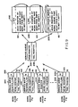
- When a processor has a plurality of stations, it may poll the stations' work queues to determine if there are control blocks to be processed. If the number of stations becomes large, however, polling the work queues may become time consuming. As an alternative to the use of polling, in one embodiment the processor may use a service queue, which is depicted in Fig. 9, which stores an identification of those work queues that were previously empty and into which a station transfers a control block. By polling the service queue, the processor can determine the work queues that have gone from being empty to being not-empty, and thus can determine the stations that require processing.
- With reference to Fig. 9, in addition to a
head pointer 60 and atail pointer 61, each work queue is further defined by a service queue pointer/link 200 and anH flag 202. The processor has a service queue also defined by ahead pointer 204 and atail pointer 206. When a work queue is empty, the service queue pointer points to, or contains the address incontrol memory 22 of, the servicequeue head pointer 204, and theH flag 202 is clear. When a station transfers a control block to an empty work queue, that is, when the work queue goes from being empty to being not-empty, the transferring station also loads an identification of the now not-empty work queue into the service queue. - Specifically, in one specific embodiment, when the transferring station loads a
control block 49 into an empty work queue, it also performs a SEND operation as depicted in Figs. 6, 7A, and 7B on the work queue, specifically altering pointer/link 200,pointers H flag 202. The transferring station first clears pointer/link 200 (step 150, Fig. 6). If the service queue was previously empty, the transferring station performssteps tail pointers H flag 202. - If the service queue is not empty, the pointer/
link 200 of each work queue in the service queue points to the next work queue in the service queue. The transferring station performssteps link 200 of the last work queue in the service queue to point to the new last work queue, and to modify theservice queue'tail pointer 206 to also point to the last work queue in the service queue, and additionally setsH flag 202. - The processor can then perform the sequence depicted in Fig. 8 to determine which previously-empty work queues are not empty, and can retrieve control blocks from the not-empty work queues without having to poll them to determine whether or not they are empty.
- The foregoing description is limited to a specific embodiment of this invention. It will be apparent, however, that this invention can be practiced in system having diverse basic construction or that use different internal circuitry than is described in the specification with the attainment of some or all of the foregoing objects and advantages of this invention.
Claims (26)
Applications Claiming Priority (2)
| Application Number | Priority Date | Filing Date | Title |
|---|---|---|---|
| US447228 | 1982-12-06 | ||
| US06/447,228 US4543626A (en) | 1982-12-06 | 1982-12-06 | Apparatus and method for controlling digital data processing system employing multiple processors |
Publications (3)
| Publication Number | Publication Date |
|---|---|
| EP0110792A2 EP0110792A2 (en) | 1984-06-13 |
| EP0110792A3 EP0110792A3 (en) | 1986-12-10 |
| EP0110792B1 true EP0110792B1 (en) | 1989-08-23 |
Family
ID=23775493
Family Applications (1)
| Application Number | Title | Priority Date | Filing Date |
|---|---|---|---|
| EP83402327A Expired EP0110792B1 (en) | 1982-12-06 | 1983-12-02 | Control arrangement for data processing system employing multiple processors |
Country Status (7)
| Country | Link |
|---|---|
| US (1) | US4543626A (en) |
| EP (1) | EP0110792B1 (en) |
| JP (1) | JPS59149548A (en) |
| AU (1) | AU560384B2 (en) |
| CA (1) | CA1206268A (en) |
| DE (1) | DE3380461D1 (en) |
| FI (1) | FI79200C (en) |
Families Citing this family (56)
| Publication number | Priority date | Publication date | Assignee | Title |
|---|---|---|---|---|
| US4939644A (en) * | 1983-05-19 | 1990-07-03 | Data General Corporation | Input/output controller for controlling the sequencing of the execution of input/output commands in a data processing system |
| US4901232A (en) * | 1983-05-19 | 1990-02-13 | Data General Corporation | I/O controller for controlling the sequencing of execution of I/O commands and for permitting modification of I/O controller operation by a host processor |
| GB8328396D0 (en) * | 1983-10-24 | 1983-11-23 | British Telecomm | Multiprocessor system |
| US4755928A (en) * | 1984-03-05 | 1988-07-05 | Storage Technology Corporation | Outboard back-up and recovery system with transfer of randomly accessible data sets between cache and host and cache and tape simultaneously |
| JPS60235269A (en) * | 1984-05-08 | 1985-11-21 | Toshiba Corp | Data transfer controller |
| US4750107A (en) * | 1985-01-07 | 1988-06-07 | Unisys Corporation | Printer-tape data link processor with DMA slave controller which automatically switches between dual output control data chomels |
| US5056003A (en) * | 1985-06-17 | 1991-10-08 | International Business Machines Corporation | Distributed data management mechanism |
| US5218713A (en) * | 1985-06-17 | 1993-06-08 | International Business Machines Corporation | Distributed data management mechanism for handling a data stream |
| JPH087662B2 (en) * | 1985-10-18 | 1996-01-29 | 株式会社日立製作所 | Data transfer control method |
| US5072368A (en) * | 1985-10-31 | 1991-12-10 | International Business Machines Corporation | Immediate duplication of I/O requests on a record by record basis by a computer operating system |
| JPH071498B2 (en) * | 1985-11-28 | 1995-01-11 | 株式会社日立製作所 | Pulse input / output processor and microcomputer using the same |
| JPH0778785B2 (en) * | 1986-03-29 | 1995-08-23 | 株式会社東芝 | Processor selection method |
| US5109484A (en) * | 1986-04-09 | 1992-04-28 | International Business Machines Corporation | Self configuring terminal which polls loop network and generates list of connected devices for use in selectively downloading control programs |
| US5274797A (en) * | 1986-05-30 | 1993-12-28 | Bull Hn Information Systems Inc. | Multiprocessor system with centralized initialization, testing and monitoring of the system and providing centralized timing |
| US4827399A (en) * | 1986-10-03 | 1989-05-02 | Nec Corporation | Common file system for a plurality of data processors |
| US4914576A (en) * | 1986-12-18 | 1990-04-03 | Bull Hn Information Systems Inc. | Apparatus and method of loading a control store memory of a central subsystem |
| US4901231A (en) * | 1986-12-22 | 1990-02-13 | American Telephone And Telegraph Company | Extended process for a multiprocessor system |
| WO1988008162A1 (en) * | 1987-04-10 | 1988-10-20 | Eip Microwave, Inc. | Data transfer system for a multiprocessor computing system |
| US5163132A (en) * | 1987-09-24 | 1992-11-10 | Ncr Corporation | Integrated controller using alternately filled and emptied buffers for controlling bi-directional data transfer between a processor and a data storage device |
| US4887076A (en) * | 1987-10-16 | 1989-12-12 | Digital Equipment Corporation | Computer interconnect coupler for clusters of data processing devices |
| US4953078A (en) * | 1987-10-28 | 1990-08-28 | Digital Equipment Corporation | Apparatus and method for multi-threaded program execution in a microcoded data processing system |
| US5159686A (en) * | 1988-02-29 | 1992-10-27 | Convex Computer Corporation | Multi-processor computer system having process-independent communication register addressing |
| US5050070A (en) * | 1988-02-29 | 1991-09-17 | Convex Computer Corporation | Multi-processor computer system having self-allocating processors |
| US5003464A (en) * | 1988-05-23 | 1991-03-26 | Bell Communications Research, Inc. | Methods and apparatus for efficient resource allocation |
| DE58909756D1 (en) * | 1988-06-17 | 1997-02-06 | Siemens Ag | Method and arrangement for executing a program in a heterogeneous multi-computer system |
| US5182798A (en) * | 1988-12-30 | 1993-01-26 | Pitney Bowes Inc. | Multiple material processing system start-up |
| US5222224A (en) * | 1989-02-03 | 1993-06-22 | Digital Equipment Corporation | Scheme for insuring data consistency between a plurality of cache memories and the main memory in a multi-processor system |
| US5109495A (en) * | 1989-02-03 | 1992-04-28 | Digital Equipment Corp. | Method and apparatus using a source operand list and a source operand pointer queue between the execution unit and the instruction decoding and operand processing units of a pipelined data processor |
| US4965793A (en) * | 1989-02-03 | 1990-10-23 | Digital Equipment Corporation | Method and apparatus for interfacing a system control unit for a multi-processor |
| US5067069A (en) * | 1989-02-03 | 1991-11-19 | Digital Equipment Corporation | Control of multiple functional units with parallel operation in a microcoded execution unit |
| US5175837A (en) * | 1989-02-03 | 1992-12-29 | Digital Equipment Corporation | Synchronizing and processing of memory access operations in multiprocessor systems using a directory of lock bits |
| US5043874A (en) * | 1989-02-03 | 1991-08-27 | Digital Equipment Corporation | Memory configuration for use with means for interfacing a system control unit for a multi-processor system with the system main memory |
| US5420981A (en) * | 1989-09-29 | 1995-05-30 | At&T Corp. | Arrangement for establishing a data pipeline in a data processing system employing multiple processors |
| CA2045756C (en) * | 1990-06-29 | 1996-08-20 | Gregg Bouchard | Combined queue for invalidates and return data in multiprocessor system |
| US5276900A (en) * | 1990-12-14 | 1994-01-04 | Stream Computers | Master connected to common bus providing synchronous, contiguous time periods having an instruction followed by data from different time period not immediately contiguous thereto |
| CA2067576C (en) * | 1991-07-10 | 1998-04-14 | Jimmie D. Edrington | Dynamic load balancing for a multiprocessor pipeline |
| US5390328A (en) * | 1992-03-30 | 1995-02-14 | International Business Machines Corporation | Data processing system and method for providing notification in a central processor of state changes for shared data structure on external storage |
| NL9201668A (en) * | 1992-09-25 | 1994-04-18 | Nederland Ptt | Method for converting a polling frequency table into a polling sequence table. |
| JP3261665B2 (en) * | 1993-01-29 | 2002-03-04 | インターナショナル・ビジネス・マシーンズ・コーポレーション | Data transfer method and data processing system |
| JP2502932B2 (en) * | 1993-01-29 | 1996-05-29 | インターナショナル・ビジネス・マシーンズ・コーポレイション | Data transfer method and data processing system |
| JP2821345B2 (en) * | 1993-09-29 | 1998-11-05 | 北海道日本電気ソフトウェア株式会社 | Asynchronous I / O control method |
| US5592683A (en) * | 1994-03-18 | 1997-01-07 | Ibm Corporation | System for selectively processing nested print commands and buffered post-print commands thereafter and resending selected portion of data stream upon error detection |
| JP2846837B2 (en) * | 1994-05-11 | 1999-01-13 | インターナショナル・ビジネス・マシーンズ・コーポレイション | Software-controlled data processing method for early detection of faults |
| US5638538A (en) * | 1995-01-13 | 1997-06-10 | Digital Equipment Corporation | Turbotable: apparatus for directing address and commands between multiple consumers on a node coupled to a pipelined system bus |
| US6523060B1 (en) * | 1995-04-07 | 2003-02-18 | Cisco Technology, Inc. | Method and apparatus for the management of queue pointers by multiple processors in a digital communications network |
| US5838915A (en) * | 1995-06-21 | 1998-11-17 | Cisco Technology, Inc. | System for buffering data in the network having a linked list for each of said plurality of queues |
| JP3120963B2 (en) * | 1995-12-14 | 2000-12-25 | 株式会社日立製作所 | Method for transferring messages and system for transferring messages |
| US6006292A (en) * | 1997-03-13 | 1999-12-21 | Adaptec, Inc. | Method of managing hardware control blocks utilizing endless queue maintained to never be empty and containing tail pointer only accessible by process executing on system processor |
| US5938747A (en) * | 1997-03-13 | 1999-08-17 | Adapter, Inc. | Hardware command block delivery queue for host adapters and other devices with onboard processors |
| US6012107A (en) * | 1997-05-22 | 2000-01-04 | Adaptec, Inc. | Hardware control block delivery queues for host adapters and other devices with onboard processors |
| US6487202B1 (en) | 1997-06-30 | 2002-11-26 | Cisco Technology, Inc. | Method and apparatus for maximizing memory throughput |
| US6526060B1 (en) | 1997-12-05 | 2003-02-25 | Cisco Technology, Inc. | Dynamic rate-based, weighted fair scheduler with explicit rate feedback option |
| US6243107B1 (en) * | 1998-08-10 | 2001-06-05 | 3D Labs Inc., Ltd. | Optimization of a graphics processor system when rendering images |
| US7181548B2 (en) | 1998-10-30 | 2007-02-20 | Lsi Logic Corporation | Command queueing engine |
| JP2003006170A (en) * | 2001-06-20 | 2003-01-10 | Hitachi Ltd | Method for performing program in environment of plural computers |
| US7991758B2 (en) * | 2005-09-07 | 2011-08-02 | International Business Machines Corporation | System and method for performing a search operation within a sequential access data storage subsystem |
Family Cites Families (10)
| Publication number | Priority date | Publication date | Assignee | Title |
|---|---|---|---|---|
| US3348210A (en) * | 1964-12-07 | 1967-10-17 | Bell Telephone Labor Inc | Digital computer employing plural processors |
| US3496551A (en) * | 1967-07-13 | 1970-02-17 | Ibm | Task selection in a multi-processor computing system |
| US3643227A (en) * | 1969-09-15 | 1972-02-15 | Fairchild Camera Instr Co | Job flow and multiprocessor operation control system |
| US3662401A (en) * | 1970-09-23 | 1972-05-09 | Collins Radio Co | Method of program execution |
| GB1443176A (en) * | 1973-04-13 | 1976-07-21 | Int Corputers Ltd | Data processor control of a plurality of devices |
| US3962685A (en) * | 1974-06-03 | 1976-06-08 | General Electric Company | Data processing system having pyramidal hierarchy control flow |
| JPS5841538B2 (en) * | 1975-12-04 | 1983-09-13 | 株式会社東芝 | Multiprocessor system instructions |
| US4149243A (en) * | 1977-10-20 | 1979-04-10 | International Business Machines Corporation | Distributed control architecture with post and wait logic |
| JPS56135266A (en) * | 1980-03-26 | 1981-10-22 | Omron Tateisi Electronics Co | Data processing system |
| US4394727A (en) * | 1981-05-04 | 1983-07-19 | International Business Machines Corporation | Multi-processor task dispatching apparatus |
-
1982
- 1982-12-06 US US06/447,228 patent/US4543626A/en not_active Expired - Lifetime
-
1983
- 1983-12-02 EP EP83402327A patent/EP0110792B1/en not_active Expired
- 1983-12-02 DE DE8383402327T patent/DE3380461D1/en not_active Expired
- 1983-12-05 CA CA000442589A patent/CA1206268A/en not_active Expired
- 1983-12-05 FI FI834449A patent/FI79200C/en not_active IP Right Cessation
- 1983-12-06 JP JP58230453A patent/JPS59149548A/en active Granted
- 1983-12-06 AU AU22122/83A patent/AU560384B2/en not_active Ceased
Also Published As
| Publication number | Publication date |
|---|---|
| FI834449A0 (en) | 1983-12-05 |
| AU560384B2 (en) | 1987-04-02 |
| EP0110792A3 (en) | 1986-12-10 |
| CA1206268A (en) | 1986-06-17 |
| FI834449A (en) | 1984-06-07 |
| AU2212283A (en) | 1984-06-14 |
| FI79200B (en) | 1989-07-31 |
| JPS6338733B2 (en) | 1988-08-02 |
| JPS59149548A (en) | 1984-08-27 |
| DE3380461D1 (en) | 1989-09-28 |
| EP0110792A2 (en) | 1984-06-13 |
| FI79200C (en) | 1989-11-10 |
| US4543626A (en) | 1985-09-24 |
Similar Documents
| Publication | Publication Date | Title |
|---|---|---|
| EP0110792B1 (en) | Control arrangement for data processing system employing multiple processors | |
| US4123795A (en) | Control system for a stored program multiprocessor computer | |
| EP0064142B1 (en) | Multiprocessor system comprising a task handling arrangement | |
| US4060849A (en) | Data input and output controller | |
| EP0116591B1 (en) | Multiprocessor system for handling interprocessor calls | |
| EP0218841B1 (en) | Lock-free serialising access to shared resources | |
| US4615001A (en) | Queuing arrangement for initiating execution of multistage transactions | |
| US4435752A (en) | Allocation of rotating memory device storage locations | |
| US4661900A (en) | Flexible chaining in vector processor with selective use of vector registers as operand and result registers | |
| US4320455A (en) | Queue structure for a data processing system | |
| US4445176A (en) | Block transfers of information in data processing networks | |
| US4435755A (en) | Balanced channel finding method | |
| KR0128274B1 (en) | Interface system and its operating method | |
| EP0389001B1 (en) | Computer vector multiprocessing control | |
| JPS6130310B2 (en) | ||
| EP0079468B1 (en) | Direct memory access method for use with a multiplexed data bus | |
| US5291581A (en) | Apparatus and method for synchronization of access to main memory signal groups in a multiprocessor data processing system | |
| US5136718A (en) | Communications arrangement for digital data processing system employing heterogeneous multiple processing nodes | |
| AU603876B2 (en) | Multiple i/o bus virtual broadcast of programmed i/o instructions | |
| JP3431941B2 (en) | Method and apparatus for determining instruction execution order in a data processing system | |
| EP0397778B1 (en) | An early start mode method and apparatus | |
| EP0206335B1 (en) | Interruption method for a data processing system | |
| EP0164972A2 (en) | Shared memory multiprocessor system | |
| JPS59106075A (en) | Data processing system | |
| EP0297892A2 (en) | Apparatus and method for control of asynchronous program interrupt events in a data processing system |
Legal Events
| Date | Code | Title | Description |
|---|---|---|---|
| PUAI | Public reference made under article 153(3) epc to a published international application that has entered the european phase |
Free format text: ORIGINAL CODE: 0009012 |
|
| AK | Designated contracting states |
Designated state(s): BE DE FR GB IT NL SE |
|
| PUAL | Search report despatched |
Free format text: ORIGINAL CODE: 0009013 |
|
| AK | Designated contracting states |
Kind code of ref document: A3 Designated state(s): BE DE FR GB IT NL SE |
|
| 17P | Request for examination filed |
Effective date: 19870717 |
|
| 17Q | First examination report despatched |
Effective date: 19881018 |
|
| GRAA | (expected) grant |
Free format text: ORIGINAL CODE: 0009210 |
|
| AK | Designated contracting states |
Kind code of ref document: B1 Designated state(s): BE DE FR GB IT NL SE |
|
| REF | Corresponds to: |
Ref document number: 3380461 Country of ref document: DE Date of ref document: 19890928 |
|
| ITF | It: translation for a ep patent filed |
Owner name: JACOBACCI & PERANI S.P.A. |
|
| ET | Fr: translation filed | ||
| PLBE | No opposition filed within time limit |
Free format text: ORIGINAL CODE: 0009261 |
|
| STAA | Information on the status of an ep patent application or granted ep patent |
Free format text: STATUS: NO OPPOSITION FILED WITHIN TIME LIMIT |
|
| 26N | No opposition filed | ||
| ITTA | It: last paid annual fee | ||
| EAL | Se: european patent in force in sweden |
Ref document number: 83402327.7 |
|
| PGFP | Annual fee paid to national office [announced via postgrant information from national office to epo] |
Ref country code: FR Payment date: 19981118 Year of fee payment: 16 |
|
| PGFP | Annual fee paid to national office [announced via postgrant information from national office to epo] |
Ref country code: SE Payment date: 19981119 Year of fee payment: 16 Ref country code: GB Payment date: 19981119 Year of fee payment: 16 |
|
| PGFP | Annual fee paid to national office [announced via postgrant information from national office to epo] |
Ref country code: DE Payment date: 19981120 Year of fee payment: 16 |
|
| PGFP | Annual fee paid to national office [announced via postgrant information from national office to epo] |
Ref country code: NL Payment date: 19981126 Year of fee payment: 16 |
|
| PGFP | Annual fee paid to national office [announced via postgrant information from national office to epo] |
Ref country code: BE Payment date: 19981210 Year of fee payment: 16 |
|
| PG25 | Lapsed in a contracting state [announced via postgrant information from national office to epo] |
Ref country code: GB Free format text: LAPSE BECAUSE OF NON-PAYMENT OF DUE FEES Effective date: 19991202 |
|
| PG25 | Lapsed in a contracting state [announced via postgrant information from national office to epo] |
Ref country code: SE Free format text: LAPSE BECAUSE OF NON-PAYMENT OF DUE FEES Effective date: 19991203 |
|
| PG25 | Lapsed in a contracting state [announced via postgrant information from national office to epo] |
Ref country code: BE Free format text: LAPSE BECAUSE OF NON-PAYMENT OF DUE FEES Effective date: 19991231 |
|
| BERE | Be: lapsed |
Owner name: DIGITAL EQUIPMENT CORP. Effective date: 19991231 |
|
| PG25 | Lapsed in a contracting state [announced via postgrant information from national office to epo] |
Ref country code: NL Free format text: LAPSE BECAUSE OF NON-PAYMENT OF DUE FEES Effective date: 20000701 |
|
| GBPC | Gb: european patent ceased through non-payment of renewal fee |
Effective date: 19991202 |
|
| REG | Reference to a national code |
Ref country code: GB Ref legal event code: 732E |
|
| EUG | Se: european patent has lapsed |
Ref document number: 83402327.7 |
|
| PG25 | Lapsed in a contracting state [announced via postgrant information from national office to epo] |
Ref country code: FR Free format text: LAPSE BECAUSE OF NON-PAYMENT OF DUE FEES Effective date: 20000831 |
|
| NLV4 | Nl: lapsed or anulled due to non-payment of the annual fee |
Effective date: 20000701 |
|
| PG25 | Lapsed in a contracting state [announced via postgrant information from national office to epo] |
Ref country code: DE Free format text: LAPSE BECAUSE OF NON-PAYMENT OF DUE FEES Effective date: 20001003 |
|
| REG | Reference to a national code |
Ref country code: FR Ref legal event code: ST |