EP0110697A2 - Mould opening and closing mechanism - Google Patents
Mould opening and closing mechanism Download PDFInfo
- Publication number
- EP0110697A2 EP0110697A2 EP83307231A EP83307231A EP0110697A2 EP 0110697 A2 EP0110697 A2 EP 0110697A2 EP 83307231 A EP83307231 A EP 83307231A EP 83307231 A EP83307231 A EP 83307231A EP 0110697 A2 EP0110697 A2 EP 0110697A2
- Authority
- EP
- European Patent Office
- Prior art keywords
- mould
- cylinder
- rod
- shaft
- closing mechanism
- Prior art date
- Legal status (The legal status is an assumption and is not a legal conclusion. Google has not performed a legal analysis and makes no representation as to the accuracy of the status listed.)
- Granted
Links
- 230000007246 mechanism Effects 0.000 title claims abstract description 41
- 239000012530 fluid Substances 0.000 claims abstract description 14
- 238000004519 manufacturing process Methods 0.000 claims abstract description 7
- 239000000969 carrier Substances 0.000 claims description 16
- 238000013459 approach Methods 0.000 description 1
- 238000010304 firing Methods 0.000 description 1
- 239000011521 glass Substances 0.000 description 1
- 239000006060 molten glass Substances 0.000 description 1
Images

Classifications
-
- C—CHEMISTRY; METALLURGY
- C03—GLASS; MINERAL OR SLAG WOOL
- C03B—MANUFACTURE, SHAPING, OR SUPPLEMENTARY PROCESSES
- C03B9/00—Blowing glass; Production of hollow glass articles
- C03B9/30—Details of blowing glass; Use of materials for the moulds
- C03B9/34—Glass-blowing moulds not otherwise provided for
- C03B9/353—Mould holders ; Mould opening and closing mechanisms
- C03B9/3537—Mechanisms for holders of half moulds moving by linear translation
Definitions
- This invention is concerned with a mould opening and closing mechanism for use in a glassware container manufacturing machine, the mechanism being operable to move a plurality of mould portions between mould open and mould closed positions thereof, each mould portion being mounted on a mould portion carrier which is mounted for pivotal movement about a vertically-extending axis.
- mould portion carriers are mounted for pivotal movement about a vertically-extending axis and are moved about said axis by a mould opening and closing mechanism.
- the mechanism comprises a shaft associated with each mould portion carrier and mounted for turning movement about a vertically-extending longitudinal axis of the shaft, an arm fixed to and projecting from each shaft, a connection between each arm and its associated mould portion carrier such that, when the shaft is turned about its longitudinal axis, the mould portion carrier is pivoted about its axis, and turning means operable to turn the shafts about their respective axes.
- the turning means comprises a piston and cylinder assembly of large diameter operable to turn-a bell crank which is connected to arms projecting from the shafts so that operation of the assembly causes two shafts to turn in opposite directions about their respective axes to move the mould portion carriers.
- a recent innovation in glassware container manufacturing machines of the individual type is a machine in which glass parisons are formed in a parison forming mould and are transferred to one of two further moulds mounted on a turntable in which the parisons are blown into containers.
- the turntable is arranged to turn about a vertical axis to bring the moulds mounted thereon successively to a parison receiving position.
- difficulty is experienced in fitting conventional mould opening and closing mechanisms as described above for two pairs of mould carriers on to the turntable because of the bulk of the mechanism.
- the invention provides a mould opening and closing mechanism for use in a glassware container manufacturing machine, the mechanism being operable to move a plurality of mould portions between mould open and mould closed positions thereof, each mould portion being mounted on a mould portion carrier which is mounted for pivotal movement about a vertically-extending axis, the mechanism comprising a shaft associated with each mould portion carrier and mounted for turning movement about a vertically-extending longitudinal axis of the shaft, an arm fixed to and projecting from each shaft, a connection between each arm and its associated mould portion carrier such that, when the shaft is turned about its longitudinal axis, the mould portion carrier is pivoted about its axis, and turning means operable to turn the shafts about their respective axes, characterised in that the turning means comprises a horizontally-extending rod associated with each shaft, a piston fixed to a central region of each rod, a cylinder slidably mounted on each rod within which cylinder the piston fixed to the rod is received so that, when fluid under pressure is introduced into the cylinder, the cylinder is caused to slide along
- the mould portion carriers are arranged in one or more pairs, each pair carrying opposed portions of the same mould, the horizontally-extending rods of the turning means associated with the or each pair are arranged parallel to one another, and the cylinders slidable on the rods are rigidly interconnected. This arrangement also assists in preventing the mechanism from becoming jammed.
- the horizontally-extending rods of the turning means associated with a first pair being arranged parallel to one another in a first horizontal plane and the horizontally-extending rods of the turning means associated with a second pair being arranged parallel to one another in a second horizontal plane directly beneath the rods of the turning means associated with the first pair.
- each rod contains passages through which fluid under pressure can enter or leave the cylinder slidable on that rod.
- each passage communicates with a plurality of longitudinally-spaced ports which enter the cylinder radially so that, as the cylinder slides on the rod, the ports are successively closed so that the motion of the cylinder is cushioned.
- the illustrative mould opening and closing mechanism is for use in a glassware container manufacturing machine having a parison-forming station (not shown) at which parisons of molten glass are formed, a container-forming station 10 at which the parisons are formed into containers, and parison transferring means (not shown) operable to transfer parisons from the parison-forming station to the container-forming station 10.
- the illustrative mould opening and closing mechanism is operable at the container-forming station 10 to move a plurality of mould portions between mould open and mould closed positions thereof.
- mould portion carriers are each mounted for pivotal movement about a vertically-extending axis on a turntable 12.
- Two of the carriers carry mould-portions of a first mould while the other two carriers carry mould portions of a second mould.
- the mould carriers may, however, carry mould portions of more than one mould which are moved together to open or close the moulds.
- the turntable is turnable about a vertical column 14 to firing the first and the second moulds successively to a parison-receiving position and to a container-releasing position.
- the mould carriers which carry mould portions of the same mould are mounted for pivotal movement about the same vertically-extending axis.
- Each mould portion carrier of the machine is pivotally connected to a link (not shown) which forms a connection between the carrier and an arm (not shown) fixed to and projecting from a shaft of the illustrative mechanism.
- the illustrative mechanism thus has four shafts, one associated with each mould portion carrier, the shafts associated with the mould portion carriers of the first mould being numbered 18 and 20 and the remaining shafts being numbered 22 and 24.
- Each shaft 18, 20, 22 and 24 is mounted on the turntable 14 for turning movement about a vertically-extending longitudinal axis of the shaft 18, 20, 22 and 24.
- connection formed by the link between the carrier and the arm is such that, when the shaft 18, 20, 22 or 24 is turned about its longitudinal axis, the carrier is pivoted about its axis and a mould portion on the carrier is moved between mould open and mould closed . positions thereof.
- the illustrative mould opening and closing mechanism also comprises turning means operable to turn the shafts 18, 20, 22 and 24 about their respective axes.
- the turning means of each shaft 18, 20, 22 and 24 is similar so that only that of the shaft 18 will be described in detail.
- Like parts associated with the shafts 18 and 20 are given the same reference numbers. However, in some cases those parts which are associated with the shafts 22 and 24 are given the same reference numbers but different from the reference numbers of the parts associated with the shafts 18 and 20.
- the turning means of the shaft 18 comprises a horizontally-extending rod 26 which extends between two upstanding frame members 28 mounted on the turntable 12 and is supported thereby.
- a piston 30 of the turning means is fixed to a central region of the rod 26, the piston 30 not being exactly halfway between the frame members 28 for reasons that will become apparent.
- a cylinder 32 of the turning means is slidably mounted on the rod 26 within which cylinder the piston 30 is received so that the piston 30 and the cylinder 32 form a piston and cylinder assembly.
- the cylinder 32 has two end caps 34 which are a sliding fit on the rod 26 and its sliding movement along the rod 26 is limited by engagement of spacing rings 36 contained within the cylinder 32 and attached to the end cap 34 with the piston 30. The arrangement is such that, when hydraulic fluid under pressure is introduced into the cylinder 32, the cylinder 32 is caused to slide along the rod 26.
- the rod 26 contains two longitudinally- extending passages 38 which enter the rod 26 from opposite ends thereof and through which fluid under pressure can enter or leave the cylinder 32.
- Each passage 38 communicates through radial passages 40 with an annular space 42 formed between the rod 26 and one of the frame members 28.
- the space 42 is connected by passages (not shown) through the frame member 28 to valves (not shown) which control entry or exit of fluid.
- Each passage 38 communicates with a port 44 which enters the cylinder 32 through the piston 30 and contains a non-return valve 46 which prevents fluid from leaving the cylinder 32 through the port 44.
- Each passage 38 also communicates with a plurality of longitudinally spaced ports 48 which enter the cylinder 32 radially so that, as the cylinder 32 slides on the rod 26, the ports 48 are successively closed by being covered by the spacing ring 36.
- the spacing ring 36 progressively throttles the exhaust by closing the ports 48 and the motion of the cylinder 32 is cushioned.
- the shafts 18 and 20 are associated with a first pair of the mould carriers which carry opposed mould portions of a first mould.
- the rods 26 of the turning means of the shafts 18 and 20 are arranged parallel to one another in a first horizontal plane.
- the cylinders 32 which are slidable on these rods 26 are rigidly interconnected by a bridge member 50 which contains a clearance slot 52 around the column 14. This ensures that the two cylinders 32 associated with the shafts 18 and 20 move together.
- the two rods 26 associated with the shafts 22 and 24 are arranged parallel to one another in a second horizontal plane directly beneath the rods 26 associated with the shafts 18 and 20.
- the rods 26 associated with the shafts 22 and 24 have cylinders 54. similar to the cylinders 32 slidable along them.
- the cylinders .54 are interconnected by a bridge member 55, similar to the bridge member 50, which has a clearance slot 56 in it.
- Each of the cylinders 32 and 54 has a boss projecting sideways therefrom, the bosses of the cylinders 32 being numbered 58 and those of the cylinders 54 being numbered 60.
- the bosses 58 are each pivotally connected to one of two links 62 which are in turn each pivotally connected to a further arm 64 which is fixed to and projects from one of the shafts 18 or 20.
- the bosses 60 are each pivotally connected to one of two links 66 ( Figure 2) which are, also pivotally connected to arms 68 fixed to and projecting from the shafts 22 and 24.
- the links 62 and 66 form connections between the arms 64 and 68 and the cylinders 32 and 54 such that, when the cylinders 32 and 54 slide along the rods 26, the shafts 18, 20, 22 and 24 are caused to turn about their respective longitudinal axes thereby moving the mould carriers.
- the shafts 18, 20, 22 and 24 are arranged at the corners of a rectangle with the shafts 18 and 20 associated with a first mould to the left (viewing Figure 1) of a central line of symmetry of the mechanism passing through the column 14 normally of the rods 26.
- the shafts 22 and 24 are to the right of this line of symmetry and so, in order to achieve symmetrical operation of the mechanism the pistons 30 of the cylinders 32 are to the left of the line of symmetry while the pistons 30 of the cylinders 54 are to the right of the line of symmetry.
- the illustrative mechanism is compact and fits readily on the turntable.
Landscapes
- Engineering & Computer Science (AREA)
- Chemical & Material Sciences (AREA)
- Manufacturing & Machinery (AREA)
- Materials Engineering (AREA)
- Organic Chemistry (AREA)
- Blow-Moulding Or Thermoforming Of Plastics Or The Like (AREA)
- Moulds For Moulding Plastics Or The Like (AREA)
- Transmission Devices (AREA)
Abstract
Description
- This invention is concerned with a mould opening and closing mechanism for use in a glassware container manufacturing machine, the mechanism being operable to move a plurality of mould portions between mould open and mould closed positions thereof, each mould portion being mounted on a mould portion carrier which is mounted for pivotal movement about a vertically-extending axis.
- In glassware container manufacturing machines of the so-called individual section type, mould portion carriers are mounted for pivotal movement about a vertically-extending axis and are moved about said axis by a mould opening and closing mechanism. The mechanism comprises a shaft associated with each mould portion carrier and mounted for turning movement about a vertically-extending longitudinal axis of the shaft, an arm fixed to and projecting from each shaft, a connection between each arm and its associated mould portion carrier such that, when the shaft is turned about its longitudinal axis, the mould portion carrier is pivoted about its axis, and turning means operable to turn the shafts about their respective axes. The turning means comprises a piston and cylinder assembly of large diameter operable to turn-a bell crank which is connected to arms projecting from the shafts so that operation of the assembly causes two shafts to turn in opposite directions about their respective axes to move the mould portion carriers.
- A recent innovation in glassware container manufacturing machines of the individual type is a machine in which glass parisons are formed in a parison forming mould and are transferred to one of two further moulds mounted on a turntable in which the parisons are blown into containers. The turntable is arranged to turn about a vertical axis to bring the moulds mounted thereon successively to a parison receiving position. In this type of machine, difficulty is experienced in fitting conventional mould opening and closing mechanisms as described above for two pairs of mould carriers on to the turntable because of the bulk of the mechanism.
- It is an object of the present invention to provide an opening and closing mechanism which is less bulky than the conventional mechanism described above.
- - The invention provides a mould opening and closing mechanism for use in a glassware container manufacturing machine, the mechanism being operable to move a plurality of mould portions between mould open and mould closed positions thereof, each mould portion being mounted on a mould portion carrier which is mounted for pivotal movement about a vertically-extending axis, the mechanism comprising a shaft associated with each mould portion carrier and mounted for turning movement about a vertically-extending longitudinal axis of the shaft, an arm fixed to and projecting from each shaft, a connection between each arm and its associated mould portion carrier such that, when the shaft is turned about its longitudinal axis, the mould portion carrier is pivoted about its axis, and turning means operable to turn the shafts about their respective axes, characterised in that the turning means comprises a horizontally-extending rod associated with each shaft, a piston fixed to a central region of each rod, a cylinder slidably mounted on each rod within which cylinder the piston fixed to the rod is received so that, when fluid under pressure is introduced into the cylinder, the cylinder is caused to slide along the rod, a further arm fixed to and projecting from the shaft, and a"connection between said further arm and the cylinder such that, when the cylinder slides along the rod, the shaft is caused to turn about its longitudinal axis.
- In a mould opening and closing mechanism as described in the last preceding paragraph, cylinders of smaller diameter can be utilised, the bell crank lever of conventional mechanism is not required and the cylinders can be arranged directly between the shafts. The mechanism is therefore less bulky than the aforementioned conventional mechanism.
- Since it is normally required to move a pair of mould portion carriers simultaneously, preferably the mould portion carriers are arranged in one or more pairs, each pair carrying opposed portions of the same mould, the horizontally-extending rods of the turning means associated with the or each pair are arranged parallel to one another, and the cylinders slidable on the rods are rigidly interconnected. This arrangement also assists in preventing the mechanism from becoming jammed.
- When the machine has two pairs of mould portion carriers, preferably the horizontally-extending rods of the turning means associated with a first pair being arranged parallel to one another in a first horizontal plane and the horizontally-extending rods of the turning means associated with a second pair being arranged parallel to one another in a second horizontal plane directly beneath the rods of the turning means associated with the first pair. This provides a compact arrangement.
- In order to protect the connections to the cylinders, preferably each rod contains passages through which fluid under pressure can enter or leave the cylinder slidable on that rod.
- In order to reduce the risk of damage to the mechanism,each passage communicates with a plurality of longitudinally-spaced ports which enter the cylinder radially so that, as the cylinder slides on the rod, the ports are successively closed so that the motion of the cylinder is cushioned.
- There now follows a detailed description, to be read with reference to the accompanying drawings, of a mould opening and closing mechanism which is illustrative of the invention. It is to be understood that the illustrative mechanism has been selected for description way of example and not of limitation of the invention. In the drawings:
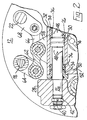
- Figure 1 is a horizontal cross-sectional view of the illustrative mechanism; and
- Figure 2 is a partial view similar to Figure 1 but showing the illustrative mechanism in a different condition thereof.
- The illustrative mould opening and closing mechanism is for use in a glassware container manufacturing machine having a parison-forming station (not shown) at which parisons of molten glass are formed, a container-forming
station 10 at which the parisons are formed into containers, and parison transferring means (not shown) operable to transfer parisons from the parison-forming station to the container-formingstation 10. The illustrative mould opening and closing mechanism is operable at the container-formingstation 10 to move a plurality of mould portions between mould open and mould closed positions thereof. - At the container-forming
station 10 of the machine, four mould portion carriers (not shown) are each mounted for pivotal movement about a vertically-extending axis on aturntable 12. Two of the carriers carry mould-portions of a first mould while the other two carriers carry mould portions of a second mould. The mould carriers may, however, carry mould portions of more than one mould which are moved together to open or close the moulds. The turntable is turnable about avertical column 14 to firing the first and the second moulds successively to a parison-receiving position and to a container-releasing position. The mould carriers which carry mould portions of the same mould are mounted for pivotal movement about the same vertically-extending axis. - Each mould portion carrier of the machine is pivotally connected to a link (not shown) which forms a connection between the carrier and an arm (not shown) fixed to and projecting from a shaft of the illustrative mechanism. The illustrative mechanism thus has four shafts, one associated with each mould portion carrier, the shafts associated with the mould portion carriers of the first mould being numbered 18 and 20 and the remaining shafts being numbered 22 and 24. Each
shaft turntable 14 for turning movement about a vertically-extending longitudinal axis of theshaft shaft - The illustrative mould opening and closing mechanism also comprises turning means operable to turn the
shafts shaft shaft 18 will be described in detail. Like parts associated with theshafts shafts shafts - The turning means of the
shaft 18 comprises a horizontally-extendingrod 26 which extends between twoupstanding frame members 28 mounted on theturntable 12 and is supported thereby. Apiston 30 of the turning means is fixed to a central region of therod 26, thepiston 30 not being exactly halfway between theframe members 28 for reasons that will become apparent. Acylinder 32 of the turning means is slidably mounted on therod 26 within which cylinder thepiston 30 is received so that thepiston 30 and thecylinder 32 form a piston and cylinder assembly. Thecylinder 32 has twoend caps 34 which are a sliding fit on therod 26 and its sliding movement along therod 26 is limited by engagement ofspacing rings 36 contained within thecylinder 32 and attached to theend cap 34 with thepiston 30. The arrangement is such that, when hydraulic fluid under pressure is introduced into thecylinder 32, thecylinder 32 is caused to slide along therod 26. - In order to introduce fluid under pressure into the
cylinder 32, therod 26 contains two longitudinally- extendingpassages 38 which enter therod 26 from opposite ends thereof and through which fluid under pressure can enter or leave thecylinder 32. Eachpassage 38 communicates throughradial passages 40 with anannular space 42 formed between therod 26 and one of theframe members 28. Thespace 42 is connected by passages (not shown) through theframe member 28 to valves (not shown) which control entry or exit of fluid. Eachpassage 38 communicates with a port 44 which enters thecylinder 32 through thepiston 30 and contains anon-return valve 46 which prevents fluid from leaving thecylinder 32 through the port 44. Eachpassage 38 also communicates with a plurality of longitudinallyspaced ports 48 which enter thecylinder 32 radially so that, as thecylinder 32 slides on therod 26, theports 48 are successively closed by being covered by thespacing ring 36. When fluid is exhausted from thecylinder 32 through theports 48, thespacing ring 36 progressively throttles the exhaust by closing theports 48 and the motion of thecylinder 32 is cushioned. - Viewing Figure 1, when it is desired to move the
cylinder 32 to the left from the position in which it is shown, fluid under pressure is introduced into theleft hand passage 38 while theright hand passage 38 is connected to exhaust. The fluid enters thecylinder 32 through the left hand port 44 and leaves through theright hand ports 48. As thecylinder 32 approaches its left hand position (shown in Figure 2), theright hand ports 48 are successively closed by theright hand ring 36 so that fluid leaving thecylinder 32 meets increasing resistance and the motion of thecylinder 32 is cushioned. For movement of thecylinder 32 to the right, the connections to thepassages 38 are reversed. - As described above, the
shafts rods 26 of the turning means of theshafts cylinders 32 which are slidable on theserods 26 are rigidly interconnected by abridge member 50 which contains aclearance slot 52 around thecolumn 14. This ensures that the twocylinders 32 associated with theshafts - The two
rods 26 associated with theshafts 22 and 24 (not visible in the drawings) are arranged parallel to one another in a second horizontal plane directly beneath therods 26 associated with theshafts rods 26 associated with theshafts cylinders 54. similar to thecylinders 32 slidable along them. The cylinders .54 are interconnected by abridge member 55, similar to thebridge member 50, which has a clearance slot 56 in it. - Each of the
cylinders cylinders 32 being numbered 58 and those of thecylinders 54 being numbered 60. Thebosses 58 are each pivotally connected to one of twolinks 62 which are in turn each pivotally connected to afurther arm 64 which is fixed to and projects from one of theshafts bosses 60 are each pivotally connected to one of two links 66 (Figure 2) which are, also pivotally connected toarms 68 fixed to and projecting from theshafts links arms cylinders cylinders rods 26, theshafts - The
shafts shafts column 14 normally of therods 26. Theshafts pistons 30 of thecylinders 32 are to the left of the line of symmetry while thepistons 30 of thecylinders 54 are to the right of the line of symmetry. - The illustrative mechanism is compact and fits readily on the turntable.
Claims (6)
Applications Claiming Priority (2)
| Application Number | Priority Date | Filing Date | Title |
|---|---|---|---|
| GB8234099 | 1982-11-30 | ||
| GB08234099A GB2131414B (en) | 1982-11-30 | 1982-11-30 | Mould opening and closing mechanism |
Publications (3)
| Publication Number | Publication Date |
|---|---|
| EP0110697A2 true EP0110697A2 (en) | 1984-06-13 |
| EP0110697A3 EP0110697A3 (en) | 1985-04-17 |
| EP0110697B1 EP0110697B1 (en) | 1987-03-25 |
Family
ID=10534628
Family Applications (1)
| Application Number | Title | Priority Date | Filing Date |
|---|---|---|---|
| EP83307231A Expired EP0110697B1 (en) | 1982-11-30 | 1983-11-28 | Mould opening and closing mechanism |
Country Status (6)
| Country | Link |
|---|---|
| US (1) | US4543118A (en) |
| EP (1) | EP0110697B1 (en) |
| JP (1) | JPS59107926A (en) |
| AU (1) | AU2179083A (en) |
| DE (1) | DE3370471D1 (en) |
| GB (1) | GB2131414B (en) |
Cited By (2)
| Publication number | Priority date | Publication date | Assignee | Title |
|---|---|---|---|---|
| EP0330397A2 (en) * | 1988-02-22 | 1989-08-30 | Vhc Limited | Mold opening and closing mechanism for an individual section (I.S.) glassware forming machine |
| FR2873321A1 (en) * | 2004-07-23 | 2006-01-27 | Inergy Automotive Systems Res | METHOD FOR FIXING AN ACCESSORY IN A FUEL TANK OF PLASTIC MATERIAL |
Families Citing this family (7)
| Publication number | Priority date | Publication date | Assignee | Title |
|---|---|---|---|---|
| GB2172591B (en) * | 1985-03-19 | 1988-07-13 | Emhart Ind | Mould opening and closing mechanism for a glassware forming machine |
| GB2172590A (en) * | 1985-03-19 | 1986-09-24 | Emhart Ind | Mould arrangement of a glassware forming machine |
| GB8618315D0 (en) * | 1986-07-26 | 1986-09-03 | Emhart Ind | Holding mould side portions in glassware forming machine |
| GB8829252D0 (en) * | 1988-12-15 | 1989-01-25 | Emhart Ind | Mould mechanisms |
| DE29916216U1 (en) * | 1999-09-15 | 2000-02-10 | Fa. Hermann Heye, 31683 Obernkirchen | Device for driving two mold half holders of a glass molding machine |
| DE102010025937A1 (en) | 2010-07-02 | 2012-01-05 | Kautex Maschinenbau Gmbh | Process for producing a plastic article and blow molding tool for carrying out the process |
| DE102012001928A1 (en) | 2012-02-02 | 2013-08-08 | Kautex Maschinenbau Gmbh | Process for producing a plastic article and part of the blow molding tool |
Citations (2)
| Publication number | Priority date | Publication date | Assignee | Title |
|---|---|---|---|---|
| US3721545A (en) * | 1969-06-25 | 1973-03-20 | Owens Illinois Inc | Multiple-cavity glass mold opening apparatus |
| US4009018A (en) * | 1975-07-07 | 1977-02-22 | Emhart Industries, Inc. | Glassware forming machine of the I. S. type with in-line mold motion |
Family Cites Families (6)
| Publication number | Priority date | Publication date | Assignee | Title |
|---|---|---|---|---|
| US1911119A (en) * | 1928-05-04 | 1933-05-23 | Hartford Empire Co | Glassware forming machine |
| US3460931A (en) * | 1966-12-29 | 1969-08-12 | Emhart Corp | Mold closing boost mechanism for glassware forming machine |
| US3591358A (en) * | 1969-04-22 | 1971-07-06 | Maul Bros Inc | Glassware mold opening and closing mechanism with unified drive means |
| JPS5515415A (en) * | 1978-07-17 | 1980-02-02 | Yamanouchi Pharmaceut Co Ltd | Heterocyclic compound and its preparation |
| JPS5511614A (en) * | 1978-07-10 | 1980-01-26 | Nippon Telegr & Teleph Corp <Ntt> | Mis field effective type transistor analog signal amplifier circuit |
| DE3024428C1 (en) * | 1980-06-28 | 1981-12-10 | Fa. Hermann Heye, 3063 Obernkirchen | Transport unit for mouth forms of a machine for the production of hollow bodies made of glass or similar thermoplastic materials |
-
1982
- 1982-11-30 GB GB08234099A patent/GB2131414B/en not_active Expired
-
1983
- 1983-11-21 US US06/553,940 patent/US4543118A/en not_active Expired - Fee Related
- 1983-11-28 DE DE8383307231T patent/DE3370471D1/en not_active Expired
- 1983-11-28 EP EP83307231A patent/EP0110697B1/en not_active Expired
- 1983-11-29 AU AU21790/83A patent/AU2179083A/en not_active Abandoned
- 1983-11-30 JP JP58226703A patent/JPS59107926A/en active Granted
Patent Citations (2)
| Publication number | Priority date | Publication date | Assignee | Title |
|---|---|---|---|---|
| US3721545A (en) * | 1969-06-25 | 1973-03-20 | Owens Illinois Inc | Multiple-cavity glass mold opening apparatus |
| US4009018A (en) * | 1975-07-07 | 1977-02-22 | Emhart Industries, Inc. | Glassware forming machine of the I. S. type with in-line mold motion |
Cited By (3)
| Publication number | Priority date | Publication date | Assignee | Title |
|---|---|---|---|---|
| EP0330397A2 (en) * | 1988-02-22 | 1989-08-30 | Vhc Limited | Mold opening and closing mechanism for an individual section (I.S.) glassware forming machine |
| EP0330397A3 (en) * | 1988-02-22 | 1990-08-29 | Maul Technology Co. | Mold opening and closing mechanism for an individual section (i.s.) glassware forming machine |
| FR2873321A1 (en) * | 2004-07-23 | 2006-01-27 | Inergy Automotive Systems Res | METHOD FOR FIXING AN ACCESSORY IN A FUEL TANK OF PLASTIC MATERIAL |
Also Published As
| Publication number | Publication date |
|---|---|
| DE3370471D1 (en) | 1987-04-30 |
| AU2179083A (en) | 1984-06-07 |
| JPS59107926A (en) | 1984-06-22 |
| EP0110697A3 (en) | 1985-04-17 |
| GB2131414A (en) | 1984-06-20 |
| GB2131414B (en) | 1986-05-08 |
| JPH0438697B2 (en) | 1992-06-25 |
| EP0110697B1 (en) | 1987-03-25 |
| US4543118A (en) | 1985-09-24 |
Similar Documents
| Publication | Publication Date | Title |
|---|---|---|
| EP0110697B1 (en) | Mould opening and closing mechanism | |
| AU2003209600A1 (en) | Method and machine for the production of hollow glassware | |
| EP0059576B1 (en) | A method of monitoring the closing action of a mould | |
| EP0195599B1 (en) | Mould opening and closing mechanism for a glassware forming machine | |
| US3834884A (en) | Apparatus for blow-molding hollow glassware in glass retaining unit | |
| US4004906A (en) | Glassware forming machine of the I. S. type for upright press and blow process | |
| EP0373769B1 (en) | Mould mechanisms for glassware-forming machines | |
| US3630709A (en) | Blowhead-operating mechanism | |
| US4588068A (en) | Parison transferring means | |
| EP0790218B1 (en) | Transfer mechanism | |
| US4002454A (en) | Glassware forming machine of the I. S. type for upright press and blow process | |
| US4612032A (en) | Glassware forming machine with parison catching device | |
| AU661088B2 (en) | Takeout device | |
| JP3239015B2 (en) | Parison transport mechanism | |
| EP3992158B1 (en) | Rotolinear mechanism for glassware-forming machines | |
| US20240300842A1 (en) | Rotolinear Mechanism for Glassware Forming Machines | |
| RU2697343C1 (en) | Method and mechanism for opening and closing molds for glass articles molding machine | |
| EP0336566A2 (en) | Opening and closing mechanism for the moulds of a glassware forming machine | |
| GB2218980A (en) | Glassware forming machine of the individual section type | |
| US2017569A (en) | Apparatus for shaping glassware | |
| GB2244538A (en) | Reducing gear train backlash |
Legal Events
| Date | Code | Title | Description |
|---|---|---|---|
| PUAI | Public reference made under article 153(3) epc to a published international application that has entered the european phase |
Free format text: ORIGINAL CODE: 0009012 |
|
| AK | Designated contracting states |
Designated state(s): DE FR IT |
|
| PUAL | Search report despatched |
Free format text: ORIGINAL CODE: 0009013 |
|
| AK | Designated contracting states |
Designated state(s): DE FR IT |
|
| RHK1 | Main classification (correction) |
Ipc: C03B 9/353 |
|
| 17P | Request for examination filed |
Effective date: 19850724 |
|
| 17Q | First examination report despatched |
Effective date: 19860716 |
|
| GRAA | (expected) grant |
Free format text: ORIGINAL CODE: 0009210 |
|
| AK | Designated contracting states |
Kind code of ref document: B1 Designated state(s): DE FR IT |
|
| REF | Corresponds to: |
Ref document number: 3370471 Country of ref document: DE Date of ref document: 19870430 |
|
| ET | Fr: translation filed | ||
| ITF | It: translation for a ep patent filed | ||
| PLBE | No opposition filed within time limit |
Free format text: ORIGINAL CODE: 0009261 |
|
| STAA | Information on the status of an ep patent application or granted ep patent |
Free format text: STATUS: NO OPPOSITION FILED WITHIN TIME LIMIT |
|
| 26N | No opposition filed | ||
| REG | Reference to a national code |
Ref country code: FR Ref legal event code: TP |
|
| ITTA | It: last paid annual fee | ||
| ITPR | It: changes in ownership of a european patent |
Owner name: CESSIONE;EMHART GLASS MACHINERY INC. |
|
| PGFP | Annual fee paid to national office [announced via postgrant information from national office to epo] |
Ref country code: FR Payment date: 19941013 Year of fee payment: 12 |
|
| PGFP | Annual fee paid to national office [announced via postgrant information from national office to epo] |
Ref country code: DE Payment date: 19941026 Year of fee payment: 12 |
|
| PG25 | Lapsed in a contracting state [announced via postgrant information from national office to epo] |
Ref country code: FR Effective date: 19960731 |
|
| PG25 | Lapsed in a contracting state [announced via postgrant information from national office to epo] |
Ref country code: DE Effective date: 19960801 |
|
| REG | Reference to a national code |
Ref country code: FR Ref legal event code: ST |