EP0110565B1 - A rotor for a rotary pump - Google Patents
A rotor for a rotary pump Download PDFInfo
- Publication number
- EP0110565B1 EP0110565B1 EP83306555A EP83306555A EP0110565B1 EP 0110565 B1 EP0110565 B1 EP 0110565B1 EP 83306555 A EP83306555 A EP 83306555A EP 83306555 A EP83306555 A EP 83306555A EP 0110565 B1 EP0110565 B1 EP 0110565B1
- Authority
- EP
- European Patent Office
- Prior art keywords
- rotor
- diameter
- ratio
- inner rotor
- circle
- Prior art date
- Legal status (The legal status is an assumption and is not a legal conclusion. Google has not performed a legal analysis and makes no representation as to the accuracy of the status listed.)
- Expired
Links
Images

Classifications
-
- F—MECHANICAL ENGINEERING; LIGHTING; HEATING; WEAPONS; BLASTING
- F04—POSITIVE - DISPLACEMENT MACHINES FOR LIQUIDS; PUMPS FOR LIQUIDS OR ELASTIC FLUIDS
- F04C—ROTARY-PISTON, OR OSCILLATING-PISTON, POSITIVE-DISPLACEMENT MACHINES FOR LIQUIDS; ROTARY-PISTON, OR OSCILLATING-PISTON, POSITIVE-DISPLACEMENT PUMPS
- F04C2/00—Rotary-piston machines or pumps
- F04C2/08—Rotary-piston machines or pumps of intermeshing-engagement type, i.e. with engagement of co-operating members similar to that of toothed gearing
- F04C2/082—Details specially related to intermeshing engagement type machines or pumps
- F04C2/084—Toothed wheels
-
- F—MECHANICAL ENGINEERING; LIGHTING; HEATING; WEAPONS; BLASTING
- F04—POSITIVE - DISPLACEMENT MACHINES FOR LIQUIDS; PUMPS FOR LIQUIDS OR ELASTIC FLUIDS
- F04C—ROTARY-PISTON, OR OSCILLATING-PISTON, POSITIVE-DISPLACEMENT MACHINES FOR LIQUIDS; ROTARY-PISTON, OR OSCILLATING-PISTON, POSITIVE-DISPLACEMENT PUMPS
- F04C2/00—Rotary-piston machines or pumps
- F04C2/08—Rotary-piston machines or pumps of intermeshing-engagement type, i.e. with engagement of co-operating members similar to that of toothed gearing
- F04C2/10—Rotary-piston machines or pumps of intermeshing-engagement type, i.e. with engagement of co-operating members similar to that of toothed gearing of internal-axis type with the outer member having more teeth or tooth-equivalents, e.g. rollers, than the inner member
- F04C2/102—Rotary-piston machines or pumps of intermeshing-engagement type, i.e. with engagement of co-operating members similar to that of toothed gearing of internal-axis type with the outer member having more teeth or tooth-equivalents, e.g. rollers, than the inner member the two members rotating simultaneously around their respective axes
-
- Y—GENERAL TAGGING OF NEW TECHNOLOGICAL DEVELOPMENTS; GENERAL TAGGING OF CROSS-SECTIONAL TECHNOLOGIES SPANNING OVER SEVERAL SECTIONS OF THE IPC; TECHNICAL SUBJECTS COVERED BY FORMER USPC CROSS-REFERENCE ART COLLECTIONS [XRACs] AND DIGESTS
- Y10—TECHNICAL SUBJECTS COVERED BY FORMER USPC
- Y10S—TECHNICAL SUBJECTS COVERED BY FORMER USPC CROSS-REFERENCE ART COLLECTIONS [XRACs] AND DIGESTS
- Y10S475/00—Planetary gear transmission systems or components
- Y10S475/904—Particular mathematical equation
-
- Y—GENERAL TAGGING OF NEW TECHNOLOGICAL DEVELOPMENTS; GENERAL TAGGING OF CROSS-SECTIONAL TECHNOLOGIES SPANNING OVER SEVERAL SECTIONS OF THE IPC; TECHNICAL SUBJECTS COVERED BY FORMER USPC CROSS-REFERENCE ART COLLECTIONS [XRACs] AND DIGESTS
- Y10—TECHNICAL SUBJECTS COVERED BY FORMER USPC
- Y10T—TECHNICAL SUBJECTS COVERED BY FORMER US CLASSIFICATION
- Y10T74/00—Machine element or mechanism
- Y10T74/19—Gearing
- Y10T74/19949—Teeth
- Y10T74/19963—Spur
- Y10T74/19972—Spur form
Definitions
- This invention relates to method of manufacture of an inner gear rotor for eccentric rotation in an outer gear rotor of a rotary gear pump and in which the inner rotor has an outer tooth profile in the shape of the inner envelope of a trochoidal curve.
- An inner rotor for the rotary pump utilising the trochoidal curve when given a diameter A of a base circle, that B of a rolling circle, an eccentricity e, and a diameter C of a rotary path as shown in Fig. 1, can obtain an inside envelope inner rotor curve TC as the envelope of circular-arc group centered on the trochoidal curve T and also a theoretical curve of an outer rotor.
- the outer rotor has a tooth profile whose cross section is defined by a plurality of circular arcs of same radius of curvature centered at equal intervals on a circle of larger diameter defining the respective outer rotor teeth, the circular arcs being located inside the larger circle, and the adjacent circular arcs being connected by radially outwardly curved arcs inside the larger circle.
- the inner rotor of this known rotary device has an outer profile in the shape of an inside envelope of a trochoidal curve.
- prior pumps of this type have been designed with a balancing of maximisation of the number of teeth and minimising the space taken up by the teeth so as to leave as much space as possible for the discharge. This has resulted in a tooth profile defining narrow and/or more sharply angled teeth.
- edges may arise from the inner rotor curve having an inner tooth form as shown in Fig. 2-(1) or -(II) according to selection of the above dimensions.
- An object of the invention is to provide a rotor for a rotary pump, which is free from creation of looped or virtual portions or edge portions and need not be corrected or smoothed as described above.
- the trochoidal dimensions are selected to satisfy the following inequality or equality:
- the present invention discloses an effective and simple method to get combinations of the values of troichoidal elements (n 1 , A, B, C, e) to satisfy this requirement; after defining e, value of n is defined as a nearest integer to d 4 /2e after which B(A), C are obtained to satisfy fc/k 1 ⁇ 1.1.
- This method makes it considerably easy for one to get combinations of the value of trochoidal elements (n 1 , A, B, C, e) to satisfy fc/k 1 ⁇ 1.1.
- the conventionally marketed rotor utilising the trochoidal curve has a ratio a of C/K o or f c /K 1 , for example, as shown in Table 1, the ratio a being such that the loop portion or edge portion as shown in Figs. 2-(1) and 2-(II) are not avoided. Hence, the correction as shown in Fig. 3-(1), 2-(II) and 3-(III) even though different in extent, has always been required.
- the invention has selected the trochoidal dimensions of the ratio ⁇ 1 for C/K o as ⁇ 40 in Table 2 and n i as the integer nearest d 4 /2e, then the inner rotor tooth form, as shown in Fig. 4-(1) and in Fig. 4-(II) of the enlarged view of portion A, has created looped or virtual portion, whereby a smooth tooth form has been obtained.
Abstract
Description
- This invention relates to method of manufacture of an inner gear rotor for eccentric rotation in an outer gear rotor of a rotary gear pump and in which the inner rotor has an outer tooth profile in the shape of the inner envelope of a trochoidal curve.
- An inner rotor for the rotary pump utilising the trochoidal curve, when given a diameter A of a base circle, that B of a rolling circle, an eccentricity e, and a diameter C of a rotary path as shown in Fig. 1, can obtain an inside envelope inner rotor curve TC as the envelope of circular-arc group centered on the trochoidal curve T and also a theoretical curve of an outer rotor.
- In a known rotary pump, the outer rotor has a tooth profile whose cross section is defined by a plurality of circular arcs of same radius of curvature centered at equal intervals on a circle of larger diameter defining the respective outer rotor teeth, the circular arcs being located inside the larger circle, and the adjacent circular arcs being connected by radially outwardly curved arcs inside the larger circle.
- The inner rotor of this known rotary device has an outer profile in the shape of an inside envelope of a trochoidal curve. In an effort to obtain maximum discharge from within the limited volume available between the inner and outer rotors while minimising pulsation of the discharge and/or reducing cavitation under high speed rotation, prior pumps of this type have been designed with a balancing of maximisation of the number of teeth and minimising the space taken up by the teeth so as to leave as much space as possible for the discharge. This has resulted in a tooth profile defining narrow and/or more sharply angled teeth.
- The edges may arise from the inner rotor curve having an inner tooth form as shown in Fig. 2-(1) or -(II) according to selection of the above dimensions.
- The tooth form in Fig. 2-(i) where the curve loops to provide a virtual portion which in practice is not realisable. In case that the tooth form in Fig. 2-(II) is directly used for the pump, bearing stress (Hertz stress) at the
edge portion 2 becomes larger to promote wear at theedge portion 2, thereby resulting in deterioration of the pump performance and increase in vibrations and noises increase. - The edge portion in Fig. 2-(II), have hitherto been corrected as shown in Fig. 3-(1) and its enlarged view in Fig. 3-(11), and the tooth form resulting from duplicate portion 1 has been corrected as shown in Fig. 3-(III).
- Such correction, however, will lead to a removal of part of the theoretical tooth profile of 6, of varying extent which corresponds to a state of wear prior to any use of the rotor and thus lowering the initial performance of pump from that which might have been attained.
- An object of the invention is to provide a rotor for a rotary pump, which is free from creation of looped or virtual portions or edge portions and need not be corrected or smoothed as described above.
- According to the invention a method of manufacture of inner gear rotor for eccentric rotation in an outer gear rotor of a rotary gear pump, comprising an inner rotor member having a centre axis and an outer peripheral profile surface whose cross section perpendicular to said centre axis is in the form of an inside envelope curve derived by moving a locus circle of diameter C with its centre on a trochoidal curve, said trochoidal curve having dimensions defined by a base circle of diameter A, a rolling circle of diameter B and an eccentricity of length e, and forming the inner rotor whereby said inner rotor member has an eccentricity ratio fe=e/B, a locus circle ratio fc=C/B and a base circle ratio n=A/B, said ratios fe, fc and n defining a quantity

characterised in that values for the parameters are selected so that said ratios have values such that fc/K1 is equal to or less than 1.1. - The invention will now be described by way of example, with reference to the accompanying partly diagrammatic drawings, in which:-
- Fig. 1 is an explanatory view of the formation of an inside envelope of a trochoidal curve for an inner rotor showing essential design dimensions;
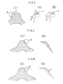
- Figs. 2-(1) and -(II) and 3-(1) are fragmentary enlarged views showing inner tooth forms of a conventional rotor,
- Fig. 3-(II) is a further enlarged view of portion A of the tooth of Fig. 3-(1),
- Fig. 3-(III) is an enlarged view of a looped virtual portion of Fig. 2-(1) when corrected or smoothed,
- Fig. 4-(1) is a fragmentary enlarged view of the tooth form of an inner rotor of the invention,
- Fig. 4-(II) is a further enlarged view of a portion A of the tooth form of Fig. 4-(i),
- Fig. 5-(1) is a fragmentary enlarged view of a further embodiment of the invention, and
- Fig. 5-(11) is a further enlarged view of a portion A of tooth form of Fig. 5-(1).
- In the rotor of the invention for a rotary pump utilising the trochoidal curve, when the base circle diameter is represented by A mm, the rolling circle diameter by B mm, the diameter of rotary path by C mm, the eccentricity by e mm, an eccentricity ratio by fe=e/B, a ratio of rotary path by f,=C/B, a ratio of base circle to rolling circle by n=A/B, a minor diameter of inner rotor by d4 (i.e. the diameter of an inner circle touching innermost portions of recesses between the gear teeth), and the number of teeth of inner rotor by n,, and


- The present invention discloses an effective and simple method to get combinations of the values of troichoidal elements (n1, A, B, C, e) to satisfy this requirement; after defining e, value of n is defined as a nearest integer to d4/2e after which B(A), C are obtained to satisfy fc/k1≦1.1. This method makes it considerably easy for one to get combinations of the value of trochoidal elements (n1, A, B, C, e) to satisfy fc/k1≦1.1.
- Furthermore, in particular, when an integer less than the value of d4/2e is defined as the value of n, fc/k1≦1.0 is obtained, while fc/k1≦1.0 is obtained when an integer over the value of d4/2e is defined as the value of n1. Therefore, it is a little more difficult in the latter case to get combinations of the values of trochoidal elements to satisfy fc/k1≦1.1 than in the former.
- It will be understood that n in n=A/B is a fraction with denominator and numerator as plus integers and n is a plus integer representing the number of teeth of the inner rotor.
- Next, an example of the invention will be concretely described.
- The conventionally marketed rotor utilising the trochoidal curve has a ratio a of C/Ko or fc/K1, for example, as shown in Table 1, the ratio a being such that the loop portion or edge portion as shown in Figs. 2-(1) and 2-(II) are not avoided. Hence, the correction as shown in Fig. 3-(1), 2-(II) and 3-(III) even though different in extent, has always been required.

- Accordingly, the invention has selected the trochoidal dimensions of the ratio α≦1 for C/Ko as φ40 in Table 2 and ni as the integer nearest d4/2e, then the inner rotor tooth form, as shown in Fig. 4-(1) and in Fig. 4-(II) of the enlarged view of portion A, has created looped or virtual portion, whereby a smooth tooth form has been obtained.
- If a is selected greater than 1, as for example, for φ23 shown in Table 2, and the integer nearest to d4/2e has been selected as n,, the result is that the loop or virtual portion is extremely diminished to an extent of being quite negligible as shown in Figs. 5-(I) and 5-(11). The contact bearing stress (Hertz stress) in this case has been not so extreme.

Claims (3)
Priority Applications (1)
| Application Number | Priority Date | Filing Date | Title |
|---|---|---|---|
| AT83306555T ATE35848T1 (en) | 1982-10-27 | 1983-10-27 | PISTON FOR ROTARY LOBE PUMP. |
Applications Claiming Priority (2)
| Application Number | Priority Date | Filing Date | Title |
|---|---|---|---|
| JP57189880A JPS5979083A (en) | 1982-10-27 | 1982-10-27 | Rotor for rotary pump |
| JP189880/82 | 1982-10-27 |
Publications (2)
| Publication Number | Publication Date |
|---|---|
| EP0110565A1 EP0110565A1 (en) | 1984-06-13 |
| EP0110565B1 true EP0110565B1 (en) | 1988-07-20 |
Family
ID=16248720
Family Applications (1)
| Application Number | Title | Priority Date | Filing Date |
|---|---|---|---|
| EP83306555A Expired EP0110565B1 (en) | 1982-10-27 | 1983-10-27 | A rotor for a rotary pump |
Country Status (6)
| Country | Link |
|---|---|
| US (2) | US4657492A (en) |
| EP (1) | EP0110565B1 (en) |
| JP (1) | JPS5979083A (en) |
| AT (1) | ATE35848T1 (en) |
| DE (1) | DE3377425D1 (en) |
| ES (1) | ES526771A0 (en) |
Families Citing this family (35)
| Publication number | Priority date | Publication date | Assignee | Title |
|---|---|---|---|---|
| CN1007545B (en) * | 1985-08-24 | 1990-04-11 | 沈培基 | Cycloidal equidistance curve gearing and its device |
| JPS62141358A (en) * | 1985-12-17 | 1987-06-24 | Sumitomo Heavy Ind Ltd | Tooth form of gearing mechanism |
| DE3702558A1 (en) * | 1987-01-29 | 1988-09-01 | Pierburg Gmbh | INNER AXIS ROTARY PISTON |
| DE68907805T2 (en) * | 1988-06-20 | 1993-11-04 | Eaton Corp | GEROTOR DESIGN WITH CONSTANT RADIAL GAME. |
| US4914330A (en) * | 1989-03-09 | 1990-04-03 | Michel Pierrat | Low speed brushless electric motor |
| US5149255A (en) * | 1990-02-20 | 1992-09-22 | Arthur D. Little, Inc. | Gearing system having interdigital concave-convex teeth formed as invalutes or multi-faceted polygons |
| US5051075A (en) * | 1990-02-20 | 1991-09-24 | Arthur D. Little, Inc. | Gearing system having interdigited teeth with convex and concave surface portions |
| US5122039A (en) * | 1990-05-29 | 1992-06-16 | Walbro Corporation | Electric-motor fuel pump |
| US5163826A (en) * | 1990-10-23 | 1992-11-17 | Cozens Eric E | Crescent gear pump with hypo cycloidal and epi cycloidal tooth shapes |
| US5135373A (en) * | 1990-11-01 | 1992-08-04 | Stackpole Limited | Spur gear with epi-cycloidal and hypo-cycloidal tooth shapes |
| US5388483A (en) * | 1992-06-03 | 1995-02-14 | Sumimoto Heavy Industries, Ltd. | Internally meshing planetary gear structure and flexible meshing type gear meshing structure |
| JP3155642B2 (en) * | 1993-02-22 | 2001-04-16 | 株式会社ユニシアジェックス | Internal oil pump |
| DE4311169C2 (en) * | 1993-04-05 | 1995-01-26 | Danfoss As | Hydraulic machine and method for generating the contour of a gear wheel of a hydraulic machine |
| DE4311168C2 (en) * | 1993-04-05 | 1995-01-12 | Danfoss As | Hydraulic machine |
| DE4311165C2 (en) * | 1993-04-05 | 1995-02-02 | Danfoss As | Hydraulic machine |
| JP3444643B2 (en) * | 1994-03-08 | 2003-09-08 | 住友重機械工業株式会社 | Internally meshing planetary gear structure and method of manufacturing the gear |
| GB2291131B (en) * | 1994-07-02 | 1998-04-08 | T & N Technology Ltd | Gerotor-type pump |
| JPH08326768A (en) * | 1995-05-29 | 1996-12-10 | Toshiba Mach Co Ltd | Spline and spline for rotary element of multi-spindle extruder |
| US5615579A (en) * | 1995-06-02 | 1997-04-01 | Shiow-Miin; Perng | Gear structure for reduction gears |
| US5813844A (en) * | 1995-12-14 | 1998-09-29 | Mitsubishi Materials Corporation | Oil pump rotor having a generated tooth shape |
| DE19651683A1 (en) * | 1996-12-12 | 1998-06-18 | Otto Eckerle | Internal gear pump without filler |
| US6077059A (en) * | 1997-04-11 | 2000-06-20 | Mitsubishi Materials Corporation | Oil pump rotor |
| US6195990B1 (en) | 1999-01-13 | 2001-03-06 | Valeo Electrical Systems, Inc. | Hydraulic machine comprising dual gerotors |
| DE10032848B4 (en) * | 1999-07-09 | 2009-04-09 | Denso Corp., Kariya-shi | Vehicle brake device with rotary pump |
| MY141586A (en) * | 2002-07-18 | 2010-05-14 | Mitsubishi Materials Pmg Corp | Oil pump rotor |
| JP4136957B2 (en) * | 2003-03-25 | 2008-08-20 | 住友電工焼結合金株式会社 | Internal gear pump |
| EP1726518A1 (en) * | 2005-05-27 | 2006-11-29 | Campagnolo Srl | Coupling profile between a central axle of a bottom bracket of a bicycle transmission and a pedal crank |
| KR100719491B1 (en) * | 2006-03-24 | 2007-05-18 | 대한소결금속 주식회사 | Design method of tooth profile for internal gear type pump |
| ES2656432T3 (en) * | 2008-08-08 | 2018-02-27 | Sumitomo Electric Sintered Alloy, Ltd. | Internal gear pump rotor, and internal gear pump that uses the rotor |
| US8277203B2 (en) * | 2009-07-02 | 2012-10-02 | Sunonwealth Electric Machine Industry Co., Ltd. | DC fan of inner rotor type |
| ES2692822T3 (en) * | 2009-11-16 | 2018-12-05 | Sumitomo Electric Sintered Alloy, Ltd. | Rotor for pump and internal gear pump that uses it |
| CN102939436B (en) | 2010-05-05 | 2016-03-23 | 能量转子股份有限公司 | Fluid energy converting device |
| US8714951B2 (en) * | 2011-08-05 | 2014-05-06 | Ener-G-Rotors, Inc. | Fluid energy transfer device |
| JP5765655B2 (en) * | 2011-10-21 | 2015-08-19 | 住友電工焼結合金株式会社 | Internal gear pump |
| JP2013148000A (en) * | 2012-01-19 | 2013-08-01 | Sumitomo Electric Sintered Alloy Ltd | Internal gear pump |
Family Cites Families (11)
| Publication number | Priority date | Publication date | Assignee | Title |
|---|---|---|---|---|
| FR917659A (en) * | 1947-02-19 | |||
| US2498848A (en) * | 1947-05-14 | 1950-02-28 | Chrysler Corp | Gear unit |
| US2965039A (en) * | 1957-03-31 | 1960-12-20 | Morita Yoshinori | Gear pump |
| US3091386A (en) * | 1959-04-23 | 1963-05-28 | Nsu Motorenwerke Ag | Cooling system for rotary mechanisms |
| US3117561A (en) * | 1960-04-26 | 1964-01-14 | Bonavera Victor | Rotor type power generating or work performing means |
| US3881847A (en) * | 1973-11-30 | 1975-05-06 | Curtiss Wright Corp | Rotary expansion engine of the type having planetating rotor |
| US3955903A (en) * | 1974-05-10 | 1976-05-11 | Aranka Elisabeth DE Dobo | Rotary piston engine with improved housing and piston configuration |
| US4395206A (en) * | 1981-04-28 | 1983-07-26 | Trochoid Power Corporation | Seal compensated geometry rotary motion device |
| JPS5870014A (en) * | 1981-10-22 | 1983-04-26 | Sumitomo Electric Ind Ltd | Oil pump |
| JPS5920591A (en) * | 1982-07-23 | 1984-02-02 | Sumitomo Electric Ind Ltd | Sintered rotor for rotary pump and method of manufacturing thereof |
| JPS59173583A (en) * | 1983-03-23 | 1984-10-01 | Sumitomo Electric Ind Ltd | Rotary pump and its rotor for lubricating oil pump in internal-combustion engine |
-
1982
- 1982-10-27 JP JP57189880A patent/JPS5979083A/en active Granted
-
1983
- 1983-10-25 US US06/545,193 patent/US4657492A/en not_active Expired - Lifetime
- 1983-10-26 ES ES526771A patent/ES526771A0/en active Granted
- 1983-10-27 AT AT83306555T patent/ATE35848T1/en not_active IP Right Cessation
- 1983-10-27 DE DE8383306555T patent/DE3377425D1/en not_active Expired
- 1983-10-27 EP EP83306555A patent/EP0110565B1/en not_active Expired
-
1985
- 1985-05-08 US US06/760,822 patent/US4673342A/en not_active Expired - Lifetime
Also Published As
| Publication number | Publication date |
|---|---|
| US4673342A (en) | 1987-06-16 |
| ES8407162A1 (en) | 1984-08-16 |
| ATE35848T1 (en) | 1988-08-15 |
| EP0110565A1 (en) | 1984-06-13 |
| JPS5979083A (en) | 1984-05-08 |
| ES526771A0 (en) | 1984-08-16 |
| DE3377425D1 (en) | 1988-08-25 |
| US4657492A (en) | 1987-04-14 |
| JPH0530997B2 (en) | 1993-05-11 |
Similar Documents
| Publication | Publication Date | Title |
|---|---|---|
| EP0110565B1 (en) | A rotor for a rotary pump | |
| KR101029624B1 (en) | Internal gear pump and inner rotor of the pump | |
| EP0010402B1 (en) | Improvements in scroll-type compressor units | |
| EP0099950A2 (en) | A sintered rotor for a rotary pump and a manufacturing method for the rotor | |
| US5813834A (en) | Centrifugal fan | |
| US6220840B1 (en) | Wall shape for scroll-type compressor vanes | |
| US4943214A (en) | Two-shaft type rotary machine having a tip circle diameter to shaft diameter within a certain range | |
| US4770574A (en) | Discs with blades | |
| US20120285282A1 (en) | Spherical involute gear coupling | |
| EP0565232B1 (en) | Liquid ring pumps with improved housing shapes | |
| EP0785360A1 (en) | Oil pump rotor | |
| US5813844A (en) | Oil pump rotor having a generated tooth shape | |
| EP0087239B1 (en) | Improved crowned spines and definition of root radius therefor | |
| US5762484A (en) | Gerotor type pump having its outer rotor shape derived from the inner rotor trochoid | |
| JPS61138893A (en) | Trochoidal oil pump | |
| JPS61268894A (en) | Vane type compressor | |
| KR101251632B1 (en) | Gerotor oil pump and method for designing the same | |
| EP0173778A1 (en) | Improvements relating to pumps | |
| JPH0419375A (en) | Internal oil motor and internal oil pump | |
| EP0066426A2 (en) | Scroll manufacturing tool | |
| EP0104265A1 (en) | Method for producing a pair of screw rotors of a screw compressor | |
| JPS6183491A (en) | Internal contact type gear pump | |
| JPH0227194A (en) | Vacuum pump | |
| JPS60128983A (en) | Driven gear for rotary gear pump | |
| JPS57108484A (en) | Pulsation-preventing pressure-balancing type vane pump |
Legal Events
| Date | Code | Title | Description |
|---|---|---|---|
| PUAI | Public reference made under article 153(3) epc to a published international application that has entered the european phase |
Free format text: ORIGINAL CODE: 0009012 |
|
| AK | Designated contracting states |
Designated state(s): AT BE CH DE FR GB IT LI LU NL SE |
|
| 17P | Request for examination filed |
Effective date: 19841127 |
|
| GRAA | (expected) grant |
Free format text: ORIGINAL CODE: 0009210 |
|
| AK | Designated contracting states |
Kind code of ref document: B1 Designated state(s): AT BE CH DE FR GB IT LI LU NL SE |
|
| REF | Corresponds to: |
Ref document number: 35848 Country of ref document: AT Date of ref document: 19880815 Kind code of ref document: T |
|
| REF | Corresponds to: |
Ref document number: 3377425 Country of ref document: DE Date of ref document: 19880825 |
|
| ET | Fr: translation filed | ||
| ITF | It: translation for a ep patent filed |
Owner name: ING. C. CORRADINI & C. S.R.L. |
|
| PLBE | No opposition filed within time limit |
Free format text: ORIGINAL CODE: 0009261 |
|
| STAA | Information on the status of an ep patent application or granted ep patent |
Free format text: STATUS: NO OPPOSITION FILED WITHIN TIME LIMIT |
|
| 26N | No opposition filed | ||
| EPTA | Lu: last paid annual fee | ||
| EAL | Se: european patent in force in sweden |
Ref document number: 83306555.0 |
|
| REG | Reference to a national code |
Ref country code: GB Ref legal event code: IF02 |
|
| PGFP | Annual fee paid to national office [announced via postgrant information from national office to epo] |
Ref country code: SE Payment date: 20021004 Year of fee payment: 20 |
|
| PGFP | Annual fee paid to national office [announced via postgrant information from national office to epo] |
Ref country code: FR Payment date: 20021008 Year of fee payment: 20 |
|
| PGFP | Annual fee paid to national office [announced via postgrant information from national office to epo] |
Ref country code: AT Payment date: 20021011 Year of fee payment: 20 |
|
| PGFP | Annual fee paid to national office [announced via postgrant information from national office to epo] |
Ref country code: GB Payment date: 20021023 Year of fee payment: 20 |
|
| PGFP | Annual fee paid to national office [announced via postgrant information from national office to epo] |
Ref country code: LU Payment date: 20021029 Year of fee payment: 20 |
|
| PGFP | Annual fee paid to national office [announced via postgrant information from national office to epo] |
Ref country code: NL Payment date: 20021031 Year of fee payment: 20 Ref country code: DE Payment date: 20021031 Year of fee payment: 20 |
|
| PGFP | Annual fee paid to national office [announced via postgrant information from national office to epo] |
Ref country code: CH Payment date: 20021101 Year of fee payment: 20 |
|
| PGFP | Annual fee paid to national office [announced via postgrant information from national office to epo] |
Ref country code: BE Payment date: 20021219 Year of fee payment: 20 |
|
| PG25 | Lapsed in a contracting state [announced via postgrant information from national office to epo] |
Ref country code: LI Free format text: LAPSE BECAUSE OF EXPIRATION OF PROTECTION Effective date: 20031026 Ref country code: GB Free format text: LAPSE BECAUSE OF EXPIRATION OF PROTECTION Effective date: 20031026 Ref country code: CH Free format text: LAPSE BECAUSE OF EXPIRATION OF PROTECTION Effective date: 20031026 |
|
| PG25 | Lapsed in a contracting state [announced via postgrant information from national office to epo] |
Ref country code: NL Free format text: LAPSE BECAUSE OF EXPIRATION OF PROTECTION Effective date: 20031027 Ref country code: LU Free format text: LAPSE BECAUSE OF EXPIRATION OF PROTECTION Effective date: 20031027 Ref country code: AT Free format text: LAPSE BECAUSE OF EXPIRATION OF PROTECTION Effective date: 20031027 |
|
| BE20 | Be: patent expired |
Owner name: *SUMITOMO ELECTRIC INDUSTRIES LTD Effective date: 20031027 |
|
| REG | Reference to a national code |
Ref country code: GB Ref legal event code: PE20 |
|
| REG | Reference to a national code |
Ref country code: CH Ref legal event code: PL |
|
| NLV7 | Nl: ceased due to reaching the maximum lifetime of a patent |
Effective date: 20031027 |
|
| EUG | Se: european patent has lapsed |