EP0110481A1 - Système d'identification de stations locales par un poste central d'interrogation - Google Patents
Système d'identification de stations locales par un poste central d'interrogation Download PDFInfo
- Publication number
- EP0110481A1 EP0110481A1 EP83201697A EP83201697A EP0110481A1 EP 0110481 A1 EP0110481 A1 EP 0110481A1 EP 83201697 A EP83201697 A EP 83201697A EP 83201697 A EP83201697 A EP 83201697A EP 0110481 A1 EP0110481 A1 EP 0110481A1
- Authority
- EP
- European Patent Office
- Prior art keywords
- station
- interrogation
- word
- circuit
- central
- Prior art date
- Legal status (The legal status is an assumption and is not a legal conclusion. Google has not performed a legal analysis and makes no representation as to the accuracy of the status listed.)
- Ceased
Links
Images
Classifications
-
- H—ELECTRICITY
- H04—ELECTRIC COMMUNICATION TECHNIQUE
- H04Q—SELECTING
- H04Q9/00—Arrangements in telecontrol or telemetry systems for selectively calling a substation from a main station, in which substation desired apparatus is selected for applying a control signal thereto or for obtaining measured values therefrom
- H04Q9/14—Calling by using pulses
Definitions
- the present invention relates to a station identification system comprising a central interrogation station and a whole series of local stations placed in parallel with one another along a transmission bus connecting them to the central station.
- a station identification system comprising a central interrogation station and a whole series of local stations placed in parallel with one another along a transmission bus connecting them to the central station.
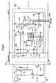
- FIGS. 1 and 2 respectively show a first and a second mode of realization of the invention.
- the station identification system described with reference to FIG. 1 comprises on the one hand a central interrogation station 10 and on the other hand a whole series of local stations 100, 200, 300, etc., placed in parallel to each other and to the central station 10, along the two connections of a transmission bus 20 (only the station 100 appears in the figures, the following stations having an identical structure and operation).
- the central station 10 comprises a transistor 11 NPN controlled by the base and the collector of which is connected to a voltage source 16, here 12 volts, by means of a resistor 12. Initially, the transistor 11 is blocked and the supply voltage, present on the collector of this transistor, is transmitted by bus 20 to be supplied to each of stations 100, 200, 300, etc. Simultaneously, the central station 10 transmits a so-called loading signal, consisting of a rectangular pulse of fairly long duration and the use of which is described below.
- station 100 In parallel on the bus 20, therefore, the stations 100, 200, 300, etc. are provided which are identical and of which only the first will be described, the station 100.
- the essential component of station 100 is a down-loading circuit with parallel loading 110 , with detection of state 0000 (expressed here by 4 bits); a component of this type is available for example from Signeties, under the reference HEF 4526 B.
- This circuit 110 receives on a terminal V DD the supply voltage (here 12 volts) transmitted by the bus 20, via a diode 120 and a capacitor 121, the association of which constitutes an RC circuit with a large time constant.
- This RC circuit also makes it possible, via a coaxial wheel 122 to an input and four outputs with which four resistors 123 to 126 respectively connected to the ground by their other end, to ensure the loading, on the four terminals P 1 to P 4 of the down-counter circuit 110, of a 4-bit digital sequence specific to each station and which therefore constitutes an identification word.
- This loading is however only authorized when a determined threshold value has been reached, that is to say only if the signal transmitted by the bus 20 has been at its high level long enough.
- the network constituted by the resistors 140, 142, the diode 141 and the capacitor 143 discriminates between the charge control signals, applied to the terminal PL of the downcounter circuit 110, and the other signals which constitute, as will be seen more far away, the interrogation pulses themselves.
- the value of the identification word is linked to the position of the coding wheel 122, which is an electrical connection member as described in patent application No. 82 12 445 filed on July 16, 1982 by the applicant company.
- This request not yet published, describes in fact a connecting member - in particular an electrical connection - between a determined number n of separate parallel tracks and a common track, and which comprises, for the establishment of the 2 n distinct combinations of links possible between this common channel and the n separate channels, 2 n-1 link arms distributed circularly around the central part of the member in 2 n-1 positions among 2n possible, these 2 n-1 positions being positions among possible, these positions being chosen so that successive circular permutations of this member establish one after the other each of these 2 n distinct combinations of possible connections between the common channel and the n parallel channels.
- this member is an electrical contactor between a common connection and four separate parallel connections, respectively connected down-circuit 110, which implies at terminals P 1 to P 4 of the down-circuit 110, which implies that the identification system described here may include up to sixteen separate stations.
- this is not a limitation of the invention, and, in order to be able to connect a higher number of stations, it suffices to provide an electrical contactor in which, according to the cited patent application, n is chosen accordingly. , or alternatively, in the case of a large number of stations, two or more contactors in cascade.
- the next phase takes place as follows.
- the central station 10 transmits, after the so-called synchronization pulse of the previous phase, a series of pulses which are all received by the local stations.
- a first characteristic of these interrogation pulses is their shorter duration compared to that of the synchronization pulse, so that the threshold value above which the loadings of the down-counter circuits of the local stations are not reached in any way. case and that the PL terminal of the down-counter circuit 110 is not requested by the discrimination network 140, 141, 142, 143.
- a second characteristic of these pulses is that they each trigger on their falling edge (passage from high level to level bàs) the action - detailed further on - down counting circuits, in synchronism with each other since a single clock signal controls these circuits.
- This return to the low level of the interrogation pulses is obtained by means of brief impulse signals sent as previously on the base of the transistor 11 of the central station 10 to turn on this transistor and, consequently, block the transistors 13 and 1 and bring the voltage on the bus to its low level.
- the signal received on the clock input CP of the down-counter circuits causes the value of the distinct 4-bit words introduced initially in these circuits to drop by one (during the loading phase).
- the terminal TC of these down-counting circuits is at the low level (substantially 0.1 to 0.2 volts ).
- the voltage on the terminal TC goes to its high level (approximately 12 volts) and, at the same time, the voltage at point X, separated from TC by a capacitor 131, increases by the same amount.
- This voltage in X like that in Z, Y and B was 12 volts before the arrival of the content of the downcounter circuit 110 in its state 0 0 0 0.
- the passage of CT from 0 to 12 volts then leads to the conduction of the transistor 130 and, consequently, maintaining the voltage at B at zero, as long as at least the voltage on the terminal CF of the down-counter circuit 110 remains above a determined threshold value (here around 5.5 volts) . From this maintenance of the conduction of transistor 130 and the low level at B, it follows that the low level of the last interrogation pulse is prolonged.
- the voltage on the TC terminal returns to its low level (by transmitting this return to zero at the same time to the CF terminal, via the capacitor 131 and the impedances 132 and 135) and the conduction of the transistor 130 is interrupted therefore, which, correlatively, puts an end to the low state observed after the interrogation pulse since the voltage at B is thus brought again to 12 volts.
- each local station has the role of transmitting a certain amount of information: in the case of a surveillance and alarm system for example, it can be foreseen that a station will have to inform the central station 10 (a ) the penetration of a person into a room (b) of an attempted break-in, the absence or existence of such events resulting in the closing or opening of an electrical contact.
- This width modulation is carried out as follows: during the passage of the voltage on the bus. At its low level, the voltage on the terminal TC passes to approximately 12 volts for the station which recognizes itself as interrogated and switches on the transistor 130 in its conduction state, so as to maintain the short circuit between the two bus connections for a variable time determined by the time constant of the different RC type circuits that can constitute the capacitor 131 and the inedances 13 ?, 133, 13 1 1 according to their combination according to the positions of the two electrical contacts 151 and 152 (the opening of the contact 151 corresponding for example to a sabotage attempt and that of the contact 152 to an intrusion detection).
- the embodiment which has just been described relates to a system in which the interrogation pulse signal transferred along the bus is only active at the level high-low level transitions.
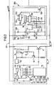
- An alternative embodiment can be proposed in which an active role is also assigned to the low level-high level transitions of the interrogation signal, namely that of a duration modulation of the interrogation signal, in order to have possibility of random access to stations, and no longer just sequential.
- the corresponding station identification system is shown in Figure 2 and its operation is as follows.
- a first loading phase makes it possible, via the same circuit comprising the diode 120, the capacitor 121, the coding wheel 122 and the resistors 123 to 126, to no longer send to a downcounter circuit, but to the four so-called first inputs of a digital comparator 150, a 4-bit word, of course different from one local station to another.
- the network composed of resistors 160 and 162, of diode 161 and of capacitor 163 determines the effective instant of taking into account this word, which is in fact applied to comparator 150 as long as capacitor 121 is in the high state, that is to say permanently as long as the pulses arrive regularly on the bus 20.
- each local station 100, 200, etc ... is entered a 1 or a 0 depending on the long or short duration of the high state of the bus before conduction of transistor 11 (that is to say before response from the station), this digital signal being available at the output of the discrimination circuit consisting of elements 160, 161, 162 and 163.
- This operation being repeated, after four introductions into the register 160, this contains the digital word which we had chosen to send in the central station 10 and which will also be present in a shift register 60.
- This digital word is sent on four inputs called second of the digital comparator 150 , which detects or not the identity between the word received during the interrogation by the central station 10 and the word loaded via the encoder wheel 122.
- a monostable rocker 170 is triggered and generates a pulse whose duration is, as in the case of the first described embodiment, function of the position of the two electrical contacts 151 and 152. This duration is also the conduction duration of the transistor 130, which functions as previously. The end of the conduction therefore occurs at four different times depending on the position of these contacts. This position can therefore be known from observation of the state of the monostable flip-flops 61 to 64, some of which, at the time of end of conduction of the transistor 130, are still active and others are not. The indication of the states of these four flip-flops is then introduced by four parallel channels into a memory 70 receiving by four other parallel channels the indication of the state of the register 60. Thus, after a complete interrogation cycle of the stations local 100, 200, etc ..., the contents of the memory exactly reflect the states of the electrical contacts of these stations, and one can thus have access to any local station in just four steps.
- the present invention is not limited to the exemplary embodiments which have just been described and shown, from which variants can be proposed without thereby departing from the scope of the invention.
- only the course of a single sequence of interrogation of the local stations by the central station has been described above. It is not uncommon in the field of surveillance that the detection of a change of state observed only once or in a fleeting manner should be considered as a false alarm. Such an alarm will then only be confirmed if detection occurs during several successive interrogation cycles.
- the system described is limited to the possibility of interrogating sixteen local stations, since the digital words specific to each of them have only four bits. It is obvious that this is not a limitation of the invention, and that the range of possible distinct digital words must be adapted to the number of stations to be connected to the system and therefore be at least equal to that -this.
Landscapes
- Engineering & Computer Science (AREA)
- Computer Networks & Wireless Communication (AREA)
- Small-Scale Networks (AREA)
- Alarm Systems (AREA)
- Time-Division Multiplex Systems (AREA)
Applications Claiming Priority (2)
| Application Number | Priority Date | Filing Date | Title |
|---|---|---|---|
| FR8220289A FR2537368A1 (fr) | 1982-12-03 | 1982-12-03 | Systeme d'identification de stations locales par un poste central d'interrogation |
| FR8220289 | 1982-12-03 |
Publications (1)
| Publication Number | Publication Date |
|---|---|
| EP0110481A1 true EP0110481A1 (fr) | 1984-06-13 |
Family
ID=9279764
Family Applications (1)
| Application Number | Title | Priority Date | Filing Date |
|---|---|---|---|
| EP83201697A Ceased EP0110481A1 (fr) | 1982-12-03 | 1983-12-01 | Système d'identification de stations locales par un poste central d'interrogation |
Country Status (4)
| Country | Link |
|---|---|
| US (1) | US4616223A (OSRAM) |
| EP (1) | EP0110481A1 (OSRAM) |
| JP (1) | JPS59122046A (OSRAM) |
| FR (1) | FR2537368A1 (OSRAM) |
Cited By (2)
| Publication number | Priority date | Publication date | Assignee | Title |
|---|---|---|---|---|
| WO1990004873A1 (de) * | 1988-10-22 | 1990-05-03 | TÖNNIES, Lise | Verfahren zum beeinflussen der belastung eines versorgungsspannungsnetzes |
| US5910578A (en) * | 1997-07-15 | 1999-06-08 | Basf Aktiengesellschaft | Phenylazoanilines |
Families Citing this family (5)
| Publication number | Priority date | Publication date | Assignee | Title |
|---|---|---|---|---|
| JPS61126393U (OSRAM) * | 1985-01-21 | 1986-08-08 | ||
| JPS62152301A (ja) * | 1985-12-24 | 1987-07-07 | Mitsubishi Electric Corp | 列車監視装置 |
| JPH0789396B2 (ja) * | 1986-04-23 | 1995-09-27 | 能美防災株式会社 | 火災報知設備 |
| EP0396535A4 (en) * | 1987-10-02 | 1992-04-01 | Tin-Ming Kuo | System and method for transferring status information between a plurality of status sites |
| US5127404A (en) * | 1990-01-22 | 1992-07-07 | Medtronic, Inc. | Telemetry format for implanted medical device |
Citations (5)
| Publication number | Priority date | Publication date | Assignee | Title |
|---|---|---|---|---|
| FR2343288A1 (fr) * | 1976-03-01 | 1977-09-30 | Laitram Corp | Systeme de donnees |
| FR2370394A1 (fr) * | 1976-11-17 | 1978-06-02 | Bendix Corp | Systeme perfectionne de transmission de donnees a conversion analogique-duree impulsionnelle-numerique |
| FR2438864A1 (fr) * | 1978-10-09 | 1980-05-09 | Masi Simone | Systeme de transmission et de centralisation d'informations |
| GB2072467A (en) * | 1979-08-29 | 1981-09-30 | Fuji Electric Co Ltd | Wire data transmission system |
| WO1981002962A1 (en) * | 1980-04-10 | 1981-10-15 | F Yong | Electrical supervisory control and data acquisition system |
Family Cites Families (2)
| Publication number | Priority date | Publication date | Assignee | Title |
|---|---|---|---|---|
| US4435706A (en) * | 1981-11-02 | 1984-03-06 | Allen-Bradley Company | Switch network |
| US4535401A (en) * | 1982-06-30 | 1985-08-13 | Texas Instruments Incorporated | Apparatus and method for providing power from master controller to subcontrollers and data communication therebetween |
-
1982
- 1982-12-03 FR FR8220289A patent/FR2537368A1/fr active Granted
-
1983
- 1983-12-01 EP EP83201697A patent/EP0110481A1/fr not_active Ceased
- 1983-12-01 JP JP58227790A patent/JPS59122046A/ja active Pending
- 1983-12-02 US US06/557,574 patent/US4616223A/en not_active Expired - Fee Related
Patent Citations (5)
| Publication number | Priority date | Publication date | Assignee | Title |
|---|---|---|---|---|
| FR2343288A1 (fr) * | 1976-03-01 | 1977-09-30 | Laitram Corp | Systeme de donnees |
| FR2370394A1 (fr) * | 1976-11-17 | 1978-06-02 | Bendix Corp | Systeme perfectionne de transmission de donnees a conversion analogique-duree impulsionnelle-numerique |
| FR2438864A1 (fr) * | 1978-10-09 | 1980-05-09 | Masi Simone | Systeme de transmission et de centralisation d'informations |
| GB2072467A (en) * | 1979-08-29 | 1981-09-30 | Fuji Electric Co Ltd | Wire data transmission system |
| WO1981002962A1 (en) * | 1980-04-10 | 1981-10-15 | F Yong | Electrical supervisory control and data acquisition system |
Cited By (2)
| Publication number | Priority date | Publication date | Assignee | Title |
|---|---|---|---|---|
| WO1990004873A1 (de) * | 1988-10-22 | 1990-05-03 | TÖNNIES, Lise | Verfahren zum beeinflussen der belastung eines versorgungsspannungsnetzes |
| US5910578A (en) * | 1997-07-15 | 1999-06-08 | Basf Aktiengesellschaft | Phenylazoanilines |
Also Published As
| Publication number | Publication date |
|---|---|
| JPS59122046A (ja) | 1984-07-14 |
| US4616223A (en) | 1986-10-07 |
| FR2537368B1 (OSRAM) | 1985-03-08 |
| FR2537368A1 (fr) | 1984-06-08 |
Similar Documents
| Publication | Publication Date | Title |
|---|---|---|
| EP0568422B1 (fr) | Circuit de détection de seuil de tension à trés faible consommation | |
| FR2585158A1 (fr) | Systeme de surveillance de conditions dangereuses | |
| FR2752126A1 (fr) | Systeme de telealimentation d'elements connectes a un reseau | |
| CH674113A5 (OSRAM) | ||
| FR2654564A1 (fr) | Interface de ligne pour un reseau de transmission d'informations. | |
| EP0680170B1 (fr) | Circuit de transmission d'un signal code en ligne sur une ligne téléphonique comprenant un synchroniseur de fréquence | |
| EP0110481A1 (fr) | Système d'identification de stations locales par un poste central d'interrogation | |
| EP0162755B1 (fr) | Circuit de commande d'un solenoide bistable | |
| EP0065181A2 (fr) | Système d'identification électronique | |
| EP0430836B1 (fr) | Dispositif de télécommande à courant porteur | |
| EP0018517A1 (fr) | Dispositif de diagnostic et d'alarme pour un réseau de communication de données | |
| CA1205893A (fr) | Interface pour relier un systeme informatique a un dispositif actionneur | |
| EP0726666B1 (fr) | Dispositif d'interfaçage entre supports de communication dans un réseau de domotique | |
| EP2320567B1 (fr) | Circuit de raccordement de capteurs | |
| EP0536011B1 (fr) | Dispositif de commande et de protection de sorties, notamment pour automate programmable | |
| EP0092879A2 (fr) | Dispositif de synchronisation bit pour modulateur-démodulateur ou récepteur de transmission de données | |
| EP0404630B1 (fr) | Dispositif de réception d'informations transitant sur deux lignes à couplage capacitif, notamment pour véhicule automobile | |
| FR2497033A1 (fr) | Attenuateur pour signal electrique | |
| BE1005974A6 (fr) | Systeme d'alarme. | |
| EP1629598B1 (fr) | Etage de sortie statique de securite | |
| BE822103A (fr) | Perfectionnements aux systemes telephoniques | |
| EP0037763A1 (fr) | Dispositif de télécommande d'appareils de chauffage raccordés à une installation d'alimentation en courant alternatif | |
| EP0584540A1 (fr) | Dispositif de surveillance de la connexion d'un appareil électrique avec une source d'alimentation | |
| FR2594575A1 (fr) | Dispositif d'autogarde pour lignes de surveillance | |
| EP0619561A1 (fr) | Circuit d'interface ayant deux bornes d'entrée et permettant conjointement d'alimenter un circuit d'application et de communiquer avec ce dernier |
Legal Events
| Date | Code | Title | Description |
|---|---|---|---|
| PUAI | Public reference made under article 153(3) epc to a published international application that has entered the european phase |
Free format text: ORIGINAL CODE: 0009012 |
|
| AK | Designated contracting states |
Designated state(s): DE FR GB |
|
| 17P | Request for examination filed |
Effective date: 19840720 |
|
| STAA | Information on the status of an ep patent application or granted ep patent |
Free format text: STATUS: THE APPLICATION HAS BEEN REFUSED |
|
| 18R | Application refused |
Effective date: 19861006 |
|
| RIN1 | Information on inventor provided before grant (corrected) |
Inventor name: NAAIJER, GEERT JAN |