EP0109977B1 - Force transferring element for use with a load cell - Google Patents
Force transferring element for use with a load cell Download PDFInfo
- Publication number
- EP0109977B1 EP0109977B1 EP82111215A EP82111215A EP0109977B1 EP 0109977 B1 EP0109977 B1 EP 0109977B1 EP 82111215 A EP82111215 A EP 82111215A EP 82111215 A EP82111215 A EP 82111215A EP 0109977 B1 EP0109977 B1 EP 0109977B1
- Authority
- EP
- European Patent Office
- Prior art keywords
- force
- force transfer
- transmitting element
- transfer member
- rolling elements
- Prior art date
- Legal status (The legal status is an assumption and is not a legal conclusion. Google has not performed a legal analysis and makes no representation as to the accuracy of the status listed.)
- Expired
Links
Images
Classifications
-
- G—PHYSICS
- G01—MEASURING; TESTING
- G01L—MEASURING FORCE, STRESS, TORQUE, WORK, MECHANICAL POWER, MECHANICAL EFFICIENCY, OR FLUID PRESSURE
- G01L1/00—Measuring force or stress, in general
- G01L1/26—Auxiliary measures taken, or devices used, in connection with the measurement of force, e.g. for preventing influence of transverse components of force, for preventing overload
Definitions
- the invention relates to a force introduction member for a load cell according to the preamble of claim 1 (see DE-B 2121 357).
- Load cells are designed to measure forces that are essentially axially directed to the load cell. For example, they are used as load cells.
- the force introduction member contains an elastic force transmission body through which the pressure force to be transmitted is transmitted to the force introduction button of the force measuring cell. Because of the elastic deformability of the force transmission body, which is located above the force introduction button of the load cell, transverse movements that occur can be absorbed. However, the transverse forces that occur exert a moment on the force introduction member that essentially depends on the size of the transverse force and the height of the elastic force transmission body. This moment leads to a measurement error in the load cell.
- a load measuring device is also known (DE-B 2121 357), in which the force to be measured is transmitted to the force introduction button of a load cell via tension members. Elastic bodies are inserted into the force transmission path, which serve as overload protection in connection with stops. As a result of the introduction of force via oscillating tension members, transverse displacements caused by transverse forces are intercepted in this device; Measurement errors due to the moments caused by the transverse forces cannot, however, be avoided.
- the object of the invention is to design a force introduction element for a load cell according to the preamble of claim 1 such that a measurement error due to a moment occurring in the force introduction element is largely avoided while maintaining the advantages of the elastic deformability of the force introduction element.
- the effective height of the elastic force transmission body above the force introduction button which significantly influences the torque that occurs as a factor, can thus be chosen independently of the actual, design-related height of the elastic force transmission body, so that the torque occurring in the force transmission body is influenced directly and to the desired extent can.
- a plate which is supported on the force introduction button is expediently provided and has a stepped edge on its periphery which carries the annular elastic force transmission body.
- At least one of the two contact surfaces of the force introduction button and the plate supported thereon is spherically curved and that the radius of curvature of the contact surfaces and the axial position, the dimensions and the physical properties of the elastic force transmission body are matched to one another in such a way that the influence of the shear force sensitivity and the influence of the eccentric force transmission in the event of shear force influence each other.
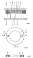
- the load cell 1 shows a load cell 1, which is attached to a foundation 2. On their top The load cell 1 carries a force introduction button 3 with a spherically curved surface 4. A plate 5 arranged above the load cell 1 has on its underside a central recess 6, the flat bottom 7 of which is supported on the spherically curved surface 4 of the force introduction button 3. The plate 5 has on its periphery a downwardly offset edge 8 which carries an annular elastic force transmission body 9 which, for example, consists of an elastomer.
- An upper plate 10 is supported with its edge on the annular elastic force transmission body 9 and carries a weighing platform 11 or another component from which the force to be measured is transmitted to the force measuring cell 1.
- the annular force transmission body 9 arranged concentrically with the force introduction button 3 is arranged approximately at the level of the spherical surface 4 of the force introduction button 3 of the force measuring cell 1. If, as a result of a lateral displacement of the plate 10, the force transmission body 9 is deformed on one side, no torque is generated in the force transmission body 9 which could have a disruptive effect on the measurement.
- the shear force is introduced into the load cell with a torque adapted to the shear force sensitivity, it can be designed as a self-compensating system.
- the elastic force transmission body 9 is not located above the force introduction button 3, but surrounds it concentrically, an advantageously low overall height is obtained.
- rolling elements 12 Figs. 2 and 3
- Balls are embedded in the power transmission body 9.
- the self-compensating effect can largely be maintained if a transverse displacement occurs predominantly only in one direction by using two opposing balls 12 which are arranged transversely to the displacement direction (arrow 13 in FIG. 2).
Description
Die Erfindung betrifft ein Krafteinleitungsglied für eine Kraftmesszelle gemäss dem Oberbegriff des Patentanspruchs 1 (siehe DE-B 2121 357). Kraftmesszellen sind zur Messung von im wesentlichen axial zur Kraftmesszelle gerichteten Kräften bestimmt. Sie werden beispielsweise als Wägezellen eingesetzt.The invention relates to a force introduction member for a load cell according to the preamble of claim 1 (see DE-B 2121 357). Load cells are designed to measure forces that are essentially axially directed to the load cell. For example, they are used as load cells.
Beim praktischen Einsatz von Kraftmesszellen treten in vielen Fällen Querbewegungen und/ oder Querkräfte auf, beispielsweise bei einer Längenänderung einer auf Kraftmesszellen abgestützten Wägebrücke. Durch die Abweichung der aus der Last und der Querkraft resultierenden Krafteinleitungsrichtung von der axialen Richtung treten Messfehler auf, deren Grösse durch die Querkraftempfindlichkeit der Kraftmesszelle bestimmt wird. Auch die aussermittige Verlagerung des Krafteinleitungspunktes bedingt einen Messfehler der Kraftmesszelle.When using load cells in practice, transverse movements and / or shear forces occur in many cases, for example when changing the length of a weighing platform supported on load cells. Due to the deviation of the force introduction direction resulting from the load and the shear force from the axial direction, measurement errors occur, the size of which is determined by the shear force sensitivity of the load cell. The off-center displacement of the force introduction point also causes a measurement error in the load cell.
In vielen praktischen Anwendungsfällen treten diese beiden Messfehler gemeinsam auf, insbesondere wenn wegen der zu erwartenden Querverschiebungen als Krafteinleitungsglied der Kraftmesszelle ein Wälzkörper verwendet wird. Bei einer solchen bekannten Kraftmesszelle (DE-C 1806668) wurden der Krümmungsradius und die Höhe des als Krafteinleitungsglied verwendeten Wälzkörpers so aufeinander abgestimmt, dass sich der Einfluss der Querkraftempfindlichkeit und der Einfluss der aussermittigen Krafteinleitung bei Querkrafteinfluss gegenseitig kompensieren. Weiterhin bedingen die Wälzkörper verhältnismässig grosse Bauhöhen; sie sind als gehärtete Präzisionsteile teuer und geben dynamische Stösse ungedämpft an die Kraftmesszelle weiter. Bei gewünschter flacher Bauweise kann man zwar eine Selbstzentrierung erreichen, nicht jedoch die Kompensationswirkung.In many practical applications, these two measurement errors occur together, especially if a rolling element is used as the force introduction element of the load cell due to the expected transverse displacements. In such a known force measuring cell (DE-C 1806668), the radius of curvature and the height of the rolling element used as a force introduction element were coordinated with one another in such a way that the influence of the sensitivity to lateral force and the influence of the eccentric force application in the event of the influence of lateral force compensate each other. Furthermore, the rolling elements require relatively large heights; As hardened precision parts, they are expensive and transmit dynamic shocks to the load cell undamped. With the desired flat design, self-centering can be achieved, but not the compensation effect.
Bei einer bekannten Kraftmesszelle (DE-U 8121 719) enthält das Krafteinleitungsglied einen elastischen Kraftübertragungskörper, durch den die zu übertragende Druckkraft auf den Krafteinleitungsknopf der Kraftmesszelle übertragen wird. Wegen der elastischen Verformbarkeit des Kraftübertragungskörpers, der sich über dem Krafteinleitungsknopf der Kraftmesszelle befindet, können auftretende Querbewegungen aufgenommen werden. Die hierbei auftretenden Querkräfte üben jedoch auf das Krafteinleitungsglied ein Moment aus, das im wesentlichen von der Grösse der Querkraft und der Höhe des elastischen Kraftübertragungskörpers abhängt. Dieses Moment führt zu einem Messfehler der Kraftmesszelle.In a known force measuring cell (DE-U 8121 719), the force introduction member contains an elastic force transmission body through which the pressure force to be transmitted is transmitted to the force introduction button of the force measuring cell. Because of the elastic deformability of the force transmission body, which is located above the force introduction button of the load cell, transverse movements that occur can be absorbed. However, the transverse forces that occur exert a moment on the force introduction member that essentially depends on the size of the transverse force and the height of the elastic force transmission body. This moment leads to a measurement error in the load cell.
Es ist weiterhin eine Lastmessvorrichtung bekannt (DE-B 2121 357), bei der die zu messende Kraft über Zugglieder auf den Krafteinleitungsknopf einer Wägezelle übertragen wird. In den Krafteinleitungsweg sind elastische Körper eingefügt, die in Verbindung mit Anschlägen als Überlastsicherung dienen. Infolge der Krafteinleitung über pendelnde Zugglieder werden bei dieser Vorrichtung zwar durch Querkräfte hervorgerufene Querverschiebungen abgefangen; Messfehler, zufolge der durch die Querkräfte hervorgerufenen Momente können jedoch nicht vermieden werden.A load measuring device is also known (DE-B 2121 357), in which the force to be measured is transmitted to the force introduction button of a load cell via tension members. Elastic bodies are inserted into the force transmission path, which serve as overload protection in connection with stops. As a result of the introduction of force via oscillating tension members, transverse displacements caused by transverse forces are intercepted in this device; Measurement errors due to the moments caused by the transverse forces cannot, however, be avoided.
Aufgabe der Erfindung ist es, ein Krafteinleitungsglied für eine Kraftmesszelle gemäss dem Oberbegriff des Patentanspruches 1 so auszugestalten, dass unter Beibehaltung der Vorteile der elastischen Verformbarkeit des Krafteinleitungsglieds ein Messfehler infolge eines im Krafteinleitungsglied auftretenden Moments weitgehend vermieden wird.The object of the invention is to design a force introduction element for a load cell according to the preamble of
Diese Aufgabe wird bei einem Krafteinleitungsglied gemäss dem Oberbegriff des Patentanspruches 1 erfindungsgemäss durch die im kennzeichnenden Teil dieses Patentanspruches angegebenen Merkmale gelöst.This object is achieved according to the invention in a force introduction member according to the preamble of
Die wirksame Höhe des elastischen Kraftübertragungskörpers über dem Krafteinleitungsknopf, die als Faktor das auftretende Moment wesentlich beeinflusst, kann somit unabhängig von der tatsächlichen, konstruktiv bedingten Höhe des elastischen Kraftübertragungskörpers frei gewählt werden, so dass das im Kraftübertragungskörper auftretende Moment unmittelbar und im gewünschten Masse beeinflusst werden kann.The effective height of the elastic force transmission body above the force introduction button, which significantly influences the torque that occurs as a factor, can thus be chosen independently of the actual, design-related height of the elastic force transmission body, so that the torque occurring in the force transmission body is influenced directly and to the desired extent can.
Auf diese Weise ist es möglich, das auftretende Moment vernachlässigbar klein werden zu lassen, indem man den ringförmigen Kraftübertragungskörper angenähert in Höhe des Krafteinleitungsknopfes der Kraftmesszelle anordnet, bzw. so ausbildet, dass die resultierende Horizontalkraft angenähert in Höhe des Krafteinleitungsknopfes wirkt. Hierzu wird zweckmässigerweise eine sich auf den Krafteinleitungsknopf abstützende Platte vorgesehen, die an ihrem Umfang einen abgesetzten Rand aufweist, der den ringförmigen elastischen Kraftübertragungskörper trägt.In this way, it is possible to make the occurring torque negligible by arranging the annular force transmission body approximately at the level of the force introduction button of the force measuring cell, or by designing it so that the resulting horizontal force acts approximately at the level of the force introduction button. For this purpose, a plate which is supported on the force introduction button is expediently provided and has a stepped edge on its periphery which carries the annular elastic force transmission body.
Gemäss einer anderen Ausgestaltung ist vorgesehen, dass mindestens eine der beiden Berührungsflächen des Krafteinleitungsknopfes und der sich darauf abstützenden Platte ballig gekrümmt ist und dass der Krümmungsradius der Berührungsflächen und die axiale Lage, die Abmessungen und die physikalischen Eigenschaften des elastischen Kraftübertragungskörpers so aufeinander abgestimmt sind, dass sich der Einfluss der Querkraftempfindlichkeit und der Einfluss der aussermittigen Krafteinleitung bei Querkrafteinfluss gegenseitig kompensieren.According to another embodiment, it is provided that at least one of the two contact surfaces of the force introduction button and the plate supported thereon is spherically curved and that the radius of curvature of the contact surfaces and the axial position, the dimensions and the physical properties of the elastic force transmission body are matched to one another in such a way that the influence of the shear force sensitivity and the influence of the eccentric force transmission in the event of shear force influence each other.
Die Erfindung wird nachfolgend an Ausführungsbeispielen näher erläutert, die in der Zeichnung dargestellt sind. Es zeigt:
- Fig. 1 in vereinfachter Darstellungsweise im Schnitt eine Kraftmesszelle,
- Fig. 2 eine Draufsicht auf einen ringförmigen Kraftübertragungskörper und
- Fig. 3 einen Schnitt längs der Linie 111-111 in Fig. 2.
- 1 in a simplified representation in section a load cell,
- Fig. 2 is a plan view of an annular power transmission body and
- 3 shows a section along the line 111-111 in FIG. 2nd
Fig. 1 zeigt eine Kraftmesszelle 1, die auf einem Fundament 2 befestigt ist. An ihrer Oberseite trägt die Kraftmesszelle 1 einen Krafteinleitungsknopf 3 mit ballig gekrümmter Oberfläche 4. Eine über der Kraftmesszelle 1 angeordnete Platte 5 weist an ihrer Unterseite eine zentrische Vertiefung 6 auf, deren ebener Boden 7 sich auf der ballig gekrümmten Fläche 4 des Krafteinleitungsknopfes 3 abstützt. Die Platte 5 weist an ihrem Umfang einen nach unten abgesetzten Rand 8 auf, der einen ringförmigen elastischen Kraftübertragungskörper 9 trägt, der beispielsweise aus einem Elastomer besteht.1 shows a
Eine obere Platte 10 stützt sich mit ihrem Rand auf dem ringförmigen elastischen Kraftübertragungskörper 9 ab und trägt eine Wägebrücke 11 oder ein anderes Bauteil, aus dem die zu messende Kraft auf die Kraftmesszelle 1 übertragen wird.An
Wie man beim dargestellten Ausführungsbeispiel erkennt, ist der konzentrisch zum Krafteinleitungsknopf 3 angeordnete ringförmige Kraftübertragungskörper 9 angenähert in Höhe der balligen Fläche 4 des Krafteinleitungsknopfes 3 der Kraftmesszelle 1 angeordnet. Wenn infolge einer seitlichen Verschiebung der Platte 10 eine einseitige Verformung des Kraftübertragungskörpers 9 erfolgt, wird dadurch kein Moment im Kraftübertragungskörper 9 erzeugt, das sich störend auf die Messung auswirken könnte.As can be seen in the exemplary embodiment shown, the annular
Wenn jedoch durch die aussermittige Krafteinleitung bei einer Schrägstellung der Platte 5 und/ oder durch eine Querkraftkomponente Fehlereinflüsse entstehen, so können diese durch eine geänderte Gestaltung des ringförmigen Kraftübertragungskörpers 9 kompensiert werden, insbesondere durch die Wahl der axialen Lage bei Schrägstellung des Kraftübertragungskörpers 9 und seiner physikalischen Eigenschaften.However, if the eccentric application of force when the
Wenn die Einleitung der Querkraft in die Kraftmesszelle mit an die Querkraftempfindlichkeit angepasstem Moment erfolgt, ist die Ausführung als selbstkompensierendes System möglich.If the shear force is introduced into the load cell with a torque adapted to the shear force sensitivity, it can be designed as a self-compensating system.
Da sich der elastische Kraftübertragungskörper 9 nicht über dem Krafteinleitungsknopf 3 befindet, sondern diesen konzentrisch umgibt, erhält man eine vorteilhafte geringe Bauhöhe.Since the elastic
Für die Fälle, bei denen die Nachgiebigkeit des elastischen Kraftübertragungskörpers 9 in Lastrichtung störend ist, z.B. bei Rohranschlüssen an einen Wägebehälter, können Abrollkörper 12 (Fig. 2 und 3), z.B. Kugeln, in den Kraftübertragungskörper 9 eingebettet werden.For the cases where the resilience of the elastic
Die selbstkompensierende Wirkung kann weitgehend beibehalten werden, wenn vorwiegend nur in einer Richtung eine Querverschiebung erfolgt, indem zwei gegenüberliegende Kugeln 12 verwendet werden, die quer zur Verschieberichtung (Pfeil 13 in Fig. 2) angeordnet sind.The self-compensating effect can largely be maintained if a transverse displacement occurs predominantly only in one direction by using two
Beim Einsatz von mehr als zwei Kugeln 12 geht die selbstkompensierende Wirkung verloren, Selbstzentrierung und flache Bauweise bleiben aber erhalten.If more than two
Claims (6)
Priority Applications (2)
| Application Number | Priority Date | Filing Date | Title |
|---|---|---|---|
| DE8282111215T DE3274013D1 (en) | 1982-12-03 | 1982-12-03 | Force transferring element for use with a load cell |
| EP82111215A EP0109977B1 (en) | 1982-12-03 | 1982-12-03 | Force transferring element for use with a load cell |
Applications Claiming Priority (1)
| Application Number | Priority Date | Filing Date | Title |
|---|---|---|---|
| EP82111215A EP0109977B1 (en) | 1982-12-03 | 1982-12-03 | Force transferring element for use with a load cell |
Publications (2)
| Publication Number | Publication Date |
|---|---|
| EP0109977A1 EP0109977A1 (en) | 1984-06-13 |
| EP0109977B1 true EP0109977B1 (en) | 1986-10-29 |
Family
ID=8189372
Family Applications (1)
| Application Number | Title | Priority Date | Filing Date |
|---|---|---|---|
| EP82111215A Expired EP0109977B1 (en) | 1982-12-03 | 1982-12-03 | Force transferring element for use with a load cell |
Country Status (2)
| Country | Link |
|---|---|
| EP (1) | EP0109977B1 (en) |
| DE (1) | DE3274013D1 (en) |
Families Citing this family (8)
| Publication number | Priority date | Publication date | Assignee | Title |
|---|---|---|---|---|
| DE3620360A1 (en) * | 1986-06-18 | 1987-12-23 | Pfister Gmbh | ELASTOSTATIC FORCE MEASURING DEVICE |
| NZ212527A (en) * | 1984-07-04 | 1988-01-08 | Arthur Kellenbach | Load measuring beam with resilient load transfer connections |
| WO1987006787A1 (en) * | 1986-04-30 | 1987-11-05 | Standard Telephones And Cables Pty. Limited | Telephone protection circuit |
| WO1988007177A1 (en) * | 1987-03-11 | 1988-09-22 | Arthur Kellenbach | Force transmission element |
| AU614077B2 (en) * | 1987-03-11 | 1991-08-22 | Arthur Kellenbach | Force transmission element |
| ATE147854T1 (en) * | 1991-01-31 | 1997-02-15 | Pfister Messtechnik | TRANSMISSION ELEMENT FOR FORCE OR TORQUE MEASURING DEVICES |
| US5509317A (en) * | 1994-10-07 | 1996-04-23 | Illinois Tool Works, Inc. | Load cell mounting |
| DE102010005792B3 (en) * | 2010-01-25 | 2011-06-16 | Innovations-Transfer Uphoff Gmbh &.Co.Kg | Pressure force measuring device |
Citations (1)
| Publication number | Priority date | Publication date | Assignee | Title |
|---|---|---|---|---|
| DE2121357B2 (en) * | 1970-05-05 | 1973-08-09 | Safelink AB, Vasteraas (Schweden) | LOAD MEASURING DEVICE |
Family Cites Families (4)
| Publication number | Priority date | Publication date | Assignee | Title |
|---|---|---|---|---|
| DE1773190A1 (en) * | 1968-04-11 | 1971-09-02 | Schenck Gmbh Carl | Load cell |
| DE2819603C2 (en) * | 1978-05-05 | 1984-09-13 | Bizerba-Werke Wilhelm Kraut Kg, 7460 Balingen | Device for the spring-loaded introduction of a measuring force into a bending rod of a balance |
| US4248317A (en) * | 1979-09-10 | 1981-02-03 | Cardinal Scale Manufacturing Company | Load cell apparatus |
| DE8116458U1 (en) * | 1981-06-03 | 1981-10-08 | Zelo Konstruktions und Vertriebs GmbH, 6148 Heppenheim | DEVICE FOR INITIATING A FORCE TO BE MEASURED IN A MEASURING CELL REQUIRED FOR PRESSURE OR BENDING |
-
1982
- 1982-12-03 EP EP82111215A patent/EP0109977B1/en not_active Expired
- 1982-12-03 DE DE8282111215T patent/DE3274013D1/en not_active Expired
Patent Citations (1)
| Publication number | Priority date | Publication date | Assignee | Title |
|---|---|---|---|---|
| DE2121357B2 (en) * | 1970-05-05 | 1973-08-09 | Safelink AB, Vasteraas (Schweden) | LOAD MEASURING DEVICE |
Also Published As
| Publication number | Publication date |
|---|---|
| EP0109977A1 (en) | 1984-06-13 |
| DE3274013D1 (en) | 1986-12-04 |
Similar Documents
| Publication | Publication Date | Title |
|---|---|---|
| EP0232514B1 (en) | Force measuring device | |
| DE4336773C2 (en) | Device for measuring pressures, forces and moments | |
| CH628433A5 (en) | FORCE TORQUE SENSOR. | |
| EP0109977B1 (en) | Force transferring element for use with a load cell | |
| EP1686358B1 (en) | Gravimetric measuring apparatus with calibrating weight | |
| EP0338325B1 (en) | Ring-shaped torsion-type force measuring device | |
| DE3620360A1 (en) | ELASTOSTATIC FORCE MEASURING DEVICE | |
| EP0499846B2 (en) | Flex-ring force transducers | |
| DE1806668B2 (en) | COMPRESSIVE FORCE SENSOR | |
| AT374004B (en) | DEVICE FOR THE SPRINGED INTRODUCTION OF A FORCE TO BE MEASURED IN A MEASURING BODY TO BE BENDED | |
| DE895065C (en) | Bridge support for scales | |
| DD218458A1 (en) | POWER-TORQUE-PROBE | |
| DE3340438A1 (en) | Measuring arrangement for force measurements by means of strain gauges | |
| DE3433829A1 (en) | SCALE WITH LOAD SUPPORT SUPPORTED | |
| DE102014013042A1 (en) | Force measuring device | |
| DE4141037C2 (en) | Device for introducing a load into a force measuring device | |
| DE3424282C2 (en) | ||
| DE2152504A1 (en) | WEIGHING CELL WITH BUILT-IN HOUSING | |
| WO2010052029A1 (en) | Force-measuring ring having an annular housing | |
| DE1017924B (en) | Linkage for the lower end of telescopic shock absorbers for motor vehicles | |
| AT226986B (en) | Weighing bridge storage on scales | |
| DE202014007167U1 (en) | Force measuring device | |
| DE1153917B (en) | Load cell with flat, elastic measuring element | |
| DE2735016A1 (en) | Low height dynamometer cell - receives force through stilt whose length is in certain ratio to radius of curvature of its contact surfaces | |
| DE19838371A1 (en) | Personal weighing scales; have force conversion device provided by flexure springs that support platform surface from base |
Legal Events
| Date | Code | Title | Description |
|---|---|---|---|
| PUAI | Public reference made under article 153(3) epc to a published international application that has entered the european phase |
Free format text: ORIGINAL CODE: 0009012 |
|
| AK | Designated contracting states |
Designated state(s): CH DE IT LI NL |
|
| 17P | Request for examination filed |
Effective date: 19840517 |
|
| RBV | Designated contracting states (corrected) |
Designated state(s): CH DE IT LI NL |
|
| ITF | It: translation for a ep patent filed |
Owner name: ING. ZINI MARANESI & C. S.R.L. |
|
| GRAA | (expected) grant |
Free format text: ORIGINAL CODE: 0009210 |
|
| AK | Designated contracting states |
Kind code of ref document: B1 Designated state(s): CH DE IT LI NL |
|
| REF | Corresponds to: |
Ref document number: 3274013 Country of ref document: DE Date of ref document: 19861204 |
|
| PLBE | No opposition filed within time limit |
Free format text: ORIGINAL CODE: 0009261 |
|
| STAA | Information on the status of an ep patent application or granted ep patent |
Free format text: STATUS: NO OPPOSITION FILED WITHIN TIME LIMIT |
|
| 26N | No opposition filed | ||
| PGFP | Annual fee paid to national office [announced via postgrant information from national office to epo] |
Ref country code: CH Payment date: 19891123 Year of fee payment: 8 |
|
| ITTA | It: last paid annual fee | ||
| PGFP | Annual fee paid to national office [announced via postgrant information from national office to epo] |
Ref country code: NL Payment date: 19891231 Year of fee payment: 8 |
|
| PGFP | Annual fee paid to national office [announced via postgrant information from national office to epo] |
Ref country code: DE Payment date: 19900103 Year of fee payment: 8 |
|
| PG25 | Lapsed in a contracting state [announced via postgrant information from national office to epo] |
Ref country code: LI Effective date: 19901231 Ref country code: CH Effective date: 19901231 |
|
| PG25 | Lapsed in a contracting state [announced via postgrant information from national office to epo] |
Ref country code: NL Effective date: 19910701 |
|
| NLV4 | Nl: lapsed or anulled due to non-payment of the annual fee | ||
| REG | Reference to a national code |
Ref country code: CH Ref legal event code: PL |
|
| PG25 | Lapsed in a contracting state [announced via postgrant information from national office to epo] |
Ref country code: DE Effective date: 19910903 |