EP0109869B1 - Digital sonar beam-forming apparatus - Google Patents
Digital sonar beam-forming apparatus Download PDFInfo
- Publication number
- EP0109869B1 EP0109869B1 EP83401973A EP83401973A EP0109869B1 EP 0109869 B1 EP0109869 B1 EP 0109869B1 EP 83401973 A EP83401973 A EP 83401973A EP 83401973 A EP83401973 A EP 83401973A EP 0109869 B1 EP0109869 B1 EP 0109869B1
- Authority
- EP
- European Patent Office
- Prior art keywords
- samples
- memory
- channel
- memories
- counter
- Prior art date
- Legal status (The legal status is an assumption and is not a legal conclusion. Google has not performed a legal analysis and makes no representation as to the accuracy of the status listed.)
- Expired
Links
Images

Classifications
-
- G—PHYSICS
- G01—MEASURING; TESTING
- G01S—RADIO DIRECTION-FINDING; RADIO NAVIGATION; DETERMINING DISTANCE OR VELOCITY BY USE OF RADIO WAVES; LOCATING OR PRESENCE-DETECTING BY USE OF THE REFLECTION OR RERADIATION OF RADIO WAVES; ANALOGOUS ARRANGEMENTS USING OTHER WAVES
- G01S15/00—Systems using the reflection or reradiation of acoustic waves, e.g. sonar systems
- G01S15/88—Sonar systems specially adapted for specific applications
- G01S15/89—Sonar systems specially adapted for specific applications for mapping or imaging
-
- G—PHYSICS
- G10—MUSICAL INSTRUMENTS; ACOUSTICS
- G10K—SOUND-PRODUCING DEVICES; METHODS OR DEVICES FOR PROTECTING AGAINST, OR FOR DAMPING, NOISE OR OTHER ACOUSTIC WAVES IN GENERAL; ACOUSTICS NOT OTHERWISE PROVIDED FOR
- G10K11/00—Methods or devices for transmitting, conducting or directing sound in general; Methods or devices for protecting against, or for damping, noise or other acoustic waves in general
- G10K11/18—Methods or devices for transmitting, conducting or directing sound
- G10K11/26—Sound-focusing or directing, e.g. scanning
- G10K11/34—Sound-focusing or directing, e.g. scanning using electrical steering of transducer arrays, e.g. beam steering
- G10K11/341—Circuits therefor
- G10K11/345—Circuits therefor using energy switching from one active element to another
Landscapes
- Engineering & Computer Science (AREA)
- Physics & Mathematics (AREA)
- Radar, Positioning & Navigation (AREA)
- Remote Sensing (AREA)
- Acoustics & Sound (AREA)
- Multimedia (AREA)
- Computer Networks & Wireless Communication (AREA)
- General Physics & Mathematics (AREA)
- Radar Systems Or Details Thereof (AREA)
- Measurement Of Velocity Or Position Using Acoustic Or Ultrasonic Waves (AREA)
Description
La présente invention se rapporte aux dispositifs de formation de voies sonar, à grande bande de fréquence. Ces voies sont formées par compensation pour chaque voie des retards géométriques des signaux reçus par les différents capteurs, formant l'antenne sonar. L'invention se rapporte à une formation de voies par des techniques numériques.The present invention relates to sonar channel training devices, with a large frequency band. These channels are formed by compensation for each channel of the geometric delays of the signals received by the various sensors, forming the sonar antenna. The invention relates to channel formation by digital techniques.
Cette invention s'applique plus particulièrement aux sonars de bateaux ou de sous-marins ayant une antenne acoustique ne présentant que peu ou pas de symétrie.This invention applies more particularly to the sonars of boats or submarines having an acoustic antenna having little or no symmetry.
Il est connu, par le brevet US 4 325 257 de former des voies dites angulaires ou spatiales, pour une antenne de N capteurs, par un dispositif numérique comportant une mémorisation des signaux, un calculateur d'adresses et un sommateur. Les N signaux reçus par ces capteurs sont multiplexés dans le temps, sont filtrés, puis sont numérisés. Un démultiplexeur distribue les valeurs des échantillons vers N mémoires vives correspondant respectivement aux N capteurs, et dans lesquelles les échantillons sont inscrits. Pour former un échantillon d'un signal de voie, N échantillons sont lus dans ces mémoires, puis sont sommés par un additionneur. Les échantillons sont lus.avec un retard prédéterminé, par rapport à l'instant où ils ont été inscrits. Ce retard est le même pour tous les échantillons d'une mémoire vive et est égal au retard à appliquer aux échantillons du signal du capteur correspondant, pour former la voie considérée. La lecture et l'écriture dans la mémoire vive sont commandées par des informations transmises par un circuit logique relié à chacune des N mémoires. Ce circuit logique reçoit ces informations en provenance d'une mémoire qui est programmée en fonction des différences de chemin entre chaque capteur et un point de focalisation de la réception. 1 It is known from US Pat. No. 4,325,257 to form so-called angular or spatial channels, for an antenna of N sensors, by a digital device comprising a storage of signals, an address calculator and a summator. The N signals received by these sensors are multiplexed in time, are filtered, and then are digitized. A demultiplexer distributes the values of the samples to N random access memories corresponding respectively to the N sensors, and in which the samples are written. To form a sample of a channel signal, N samples are read from these memories, then summed by an adder. The samples are read with a predetermined delay, compared to the moment when they were recorded. This delay is the same for all the samples of a random access memory and is equal to the delay to be applied to the samples of the signal from the corresponding sensor, to form the channel considered. Reading and writing in the RAM are controlled by information transmitted by a logic circuit connected to each of the N memories. This logic circuit receives this information from a memory which is programmed as a function of the path differences between each sensor and a reception focal point. 1
Pour former un grand nombre de voies, avec ce dispositif suivant l'art antérieur, il faut utiliser un grand nombre de circuits de formation en parallèle.To form a large number of channels, with this device according to the prior art, it is necessary to use a large number of parallel training circuits.
Le dispositif, suivant l'invention, a l'avantage par rapport à ce dispositif, suivant l'art antérieur, de permettre l'utilisation d'un générateur d'adresses commun à tous les circuits de calcul, ce qui réduit considérablement le volume de matériel nécessaire, par rapport à l'art antérieur.The device according to the invention has the advantage over this device, according to the prior art, of allowing the use of an address generator common to all the computing circuits, which considerably reduces the volume of necessary material, compared to the prior art.
Selon l'invention, un dispositif numérique de formation de D voies spatiales pour un sonar ayant une antenne acoustique comportant N capteurs, ledit dispositif comprenant :
- - des moyens d'échantillonnage et de multiplexage comportant N entrées dont chacune est reliée à l'un des capteurs, et une sortie fournissant séquentiellement des groupes de N échantillons des signaux reçus par les entrées,
- - des moyens de mémorisation composés de plusieurs mémoires vives identiques, de nombre B, ayant un temps d'accès to et dont chacune est agencée pour stocker un nombre prédéterminé d'échantillons, la capacité totale desdits moyens de mémorisation étant supérieure à la durée TmaX la plus grande des retards à réaliser pour la formation de voies,
- - des moyens d'adressage pour l'écriture et la lecture de ces échantillons dans les mémoires vives, lesdits moyens comportant des moyens pour déterminer les adresses de lecture en fonction des retards nécessaires pour former les voies,
- - des moyens de sommation combinant M échantillons lus dans les mémoires vives pour constituer un échantillon d'un signal de voie,
ledit dispositif étant caractérisé en ce que - - les mémoires vives sont reliées en série, la première étant reliée à la sortie des moyens d'échantillonnage et de multiplexage, et
- - les moyens d'adressage comportent des générateurs d'adresses fournissant une suite d'adresses d'écriture identiques pour toutes les mémoires vives et une suite d'adresses de lecture identiques pour toutes les mémoires vives, lesdites adresses d'écriture étant telles qu'elles assurent des transferts d'échantillons à des intervalles de temps réguliers d'une mémoire vive à la suivante, lesdites adresses de lecture comportant deux parties fonction des retards ainsi que des périodes de temps Tv entre les échantillons de signaux de voie de chaque voie, la première desdites parties étant destinée à sélectionner, parmi les mémoires vives, Q mémoires dont les échantillons sont utilisés dans la formation simultanée de Q échantillons de signal de voie d'une même voie tandis que la deuxième partie sélectionne, dans les mémoires sélectionnées, les échantillons utilisés dans la formation de ladite voie.
- - sampling and multiplexing means comprising N inputs, each of which is connected to one of the sensors, and an output sequentially supplying groups of N samples of the signals received by the inputs,
- storage means composed of several identical random access memories, of number B, having an access time t 0 and each of which is arranged to store a predetermined number of samples, the total capacity of said storage means being greater than the duration TmaX, the biggest delay to realize for lane formation,
- addressing means for writing and reading these samples in random access memories, said means comprising means for determining the reading addresses as a function of the delays necessary to form the channels,
- - summation means combining M samples read from the random access memories to constitute a sample of a channel signal,
said device being characterized in that - the random access memories are connected in series, the first being connected to the output of the sampling and multiplexing means, and
- the addressing means comprise address generators providing a series of identical write addresses for all the random access memories and a series of identical read addresses for all the random memories, said write addresses being such that '' they ensure transfers of samples at regular time intervals from one random access memory to the next, said read addresses comprising two parts which are a function of the delays as well as time periods T v between the samples of channel signals of each channel, the first of said parts being intended to select, from random access memories, Q memories whose samples are used in the simultaneous formation of Q samples of channel signal from the same channel while the second part selects, from the selected memories , the samples used in the formation of said path.
D'autres caractéristiques et avantages ressortiront de la description qui va suivre illustrée par les figures qui représentent :
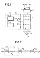
- - figure 1, un dispositif de formation de voies numérique, suivant l'art antérieur ;
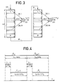
- - figure 2, une représentation temporelle des cycles écriture-lecture pour ce dispositif, suivant l'art antérieur ;
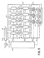
- - figure 3, un schéma explicatif pour la formation de voies, suivant l'invention ;
- - figure 4, une représentation temporelle des cycles écriture-lecture, suivant l'invention ;
- - figure 5, un exemple de réalisation de dispositif de formation de voies, suivant l'invention ;
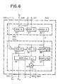
- - figure 6, un exemple générateur d'adresses pour le dispositif de formation de voies, suivant l'invention ;
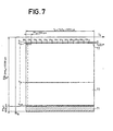
- - figures 7 et 8, les diagrammes temporels des voies formées, suivant l'invention.
- - Figure 1, a digital channel training device, according to the prior art;
- - Figure 2, a temporal representation of the write-read cycles for this device, according to the prior art;
- - Figure 3, an explanatory diagram for the formation of channels, according to the invention;
- - Figure 4, a temporal representation of the write-read cycles, according to the invention;
- - Figure 5, an exemplary embodiment of the channel forming device according to the invention;
- - Figure 6, an example generator addresses for the channel forming device according to the invention;
- - Figures 7 and 8, the time diagrams of the channels formed, according to the invention.
Il est connu que la surveillance d'un secteur angulaire par un sonar s'effectue par la formation de plusieurs voies directives pointées dans des directions prédéterminées, régulièrement espacées dans la plupart des cas.It is known that the surveillance of an angular sector by a sonar is carried out by the formation of several directional routes pointed in predetermined directions, regularly spaced in most cases.
Chaque voie formée est adaptée à une direction particulière d'indice k pour laquelle les retards électriques introduits par la formation de voie permettent la remise en synchronisme des signaux issus des différents capteurs de l'antenne lorsqu'une onde plane, ou sphérique si l'antenne est destinée à travailler en champ proche, provient de la direction repérée par l'indice « k ».Each channel formed is adapted to a particular direction of index k for which the electrical delays introduced by the channel formation allow synchronization of the signals from the different sensors of the antenna when a plane wave, or spherical if the antenna is intended to work in near field, comes from the direction indicated by the index “k”.
Après introduction des retards électriques, les signaux de réception sont pondérés en amplitude et additionnés, soit :![]()
![]()
La figure 1 représente le synoptique de formation de voies, suivant l'art antérieur. Les échantillons numériques des signaux s1, ... si, ... sN fournis par les N capteurs sont multiplexés séquentiellement dans un multiplexeur 10, piloté par une horloge H, et sont stockés dans une mémoire vive à accès aléatoire 11, type RAM. Un générateur d'adresses 12 fournit les adresses d'écriture AE et de lecture AL à cette mémoire 11. Cette mémoire travaille alternativement en mode écriture et en mode lecture. Le mode écriture correspond à l'acquisition des N échantillons en sortie du multiplexeur 10. Le mode de lecture est utilisé pour le calcul des voies, qui sont obtenues en sortie d'un sommateur 13, recevant les échantillons lus dans la mémoire 11 aux adresses où sont stockés les échantillons ayant les retards nécessaires à la voie à former.Figure 1 shows the block formation diagram according to the prior art. The digital samples of the signals s 1 , ... s i , ... s N supplied by the N sensors are sequentially multiplexed in a
La figure 2 représente le séquencement écriture-lecture au niveau de la mémoire. La période Ts représente la période d'échantillonnage de chaque signal de capteur. Le temps TEO correspond à la durée d'écriture des N échantillons et le temps de lecture TLO = TS―TEO.FIG. 2 represents the writing-reading sequencing at the memory level. The period T s represents the sampling period of each sensor signal. The time T EO corresponds to the writing time of the N samples and the reading time T LO = T S ―T EO .
En écriture, la mémoire est gérée de manière à ce que entre deux périodes Ts l'adresse d'écriture AE soit incrémentée de N, les échantillons étant rangés successivement à partir de cette adresse. La mémoire 11 se trouve ainsi remplie d'une succession de Po groupes G1, ... GPo de N échantillons séparés d'un temps Ts. Soit τmax la plus grande valeur des retards τik. On pose A · Ts = τmax· Cette valeur A · Ts sera désignée par la suite par profondeur d'antenne. Pour former toutes les voies il faut que Po soit supérieur ou égal à A.In writing, the memory is managed so that between two periods T s the writing address A E is incremented by N, the samples being arranged successively from this address. The memory 11 is thus filled with a succession of P o groups G 1 , ... G Po of N samples separated by a time T s . Let τ max be the greatest value of the delays τ ik. We set A · T s = τ max · This value A · T s will be designated below by antenna depth. To form all the channels, P o must be greater than or equal to A.
Les adresses d'écriture AE pour les P groupes de N échantillons sont fournies par un compteur 120, recevant les signaux d'horloge H.The write addresses A E for the P groups of N samples are supplied by a
En lecture, un échantillon de signal de la voie « k est formé en lisant un échantillon de chaque capteur « i » dans les groupes correspondant aux retards τik. Pour cela le générateur d'adresses 121 fournit à la mémoire 11 les adresses de lecture AL des M échantillons nécessaires pour former un échantillon de voie car généralement on n'utilise pour former chaque voie qu'une partie des N capteurs de l'antenne. Le générateur d'adresses 121 effectue l'addition de l'adresse d'écriture, qui s'incrémente d'une unité à chaque période d'échantillonnage Ts du signal d'entrée, avec les retards quantifiés τik lus dans une mémoire à lecture seule d'accès aléatoire, type PROM. Cette mémoire des retards fournit également l'indice i du capteur à utiliser à chaque étape du calcul et éventuellement la pondération d'amplitude Aik à appliquer aux signaux s1, ... sN des capteurs avant sommation, suivant la relation (1). Chaque signal Vk(t), défini suivant cette relation (1), constitue ce que l'on appelle un échantillon temporel à l'instant t de la voie spatiale k.In reading, a signal sample from channel “k is formed by reading a sample from each sensor“ i ”in the groups corresponding to the delays τ ik . For this, the
Pour chaque voie il faut obtenir au moins un tel échantillon pendant une période Tv, où Tv correspond à la règle de Shannon : Tv = 1/2B, B étant la bande passante nécessaire. La période d'échantillonnage Ts est déterminée par la précision nécessaire pour les retards et l'on a généralement Ts ≤ Tv.For each channel, it is necessary to obtain at least one such sample during a period T v , where T v corresponds to Shannon's rule: T v = 1 / 2B, B being the necessary bandwidth. The sampling period T s is determined by the precision necessary for the delays and we generally have T s ≤ T v .
Il en résulte que pendant le temps de lecture-calcul TL on ne peut calculer que K voies, où K est donné par la relation :
- N = 64, M = 24, Ts = 16 µs, Tv = 32 µs et to = 0,125 µs ;
- On trouve :
- K=5.
- N = 64, M = 24, T s = 16 µs, T v = 32 µs and t o = 0.125 µs;
- We find :
- K = 5.
Pour former un plus grand nombre de voies, suivant l'art antérieur, il faut utiliser plusieurs dispositifs en parallèle, chaque mémoire stockant des échantillons de capteurs identiques sur une durée égale, comme précédemment, à la profondeur d'antenne.To form a greater number of channels, according to the prior art, it is necessary to use several devices in parallel, each memory storing samples of identical sensors over a period equal, as previously, to the antenna depth.
Si l'antenne possède une symétrie circulaire, les différents circuits de calcul peuvent être pilotés par un même générateur d'adresses. Cependant si les voies préformées doivent être stabilisées, en corrigeant les mouvements de l'antenne, en roulis et tangage par exemple, la symétrie circulaire disparaît. Pour une antenne quelconque, il y aura donc autant de générateurs d'adresses, tels que 12, que de circuits formateurs, un circuit formateur étant défini comme l'ensemble mémoire 11 et sommateur 13. Or actuellement un générateur d'adresses comporte 2 à 3 fois plus de composants qu'un circuit formateur, ce qui conduit à des volumes de matériel importants.If the antenna has circular symmetry, the different calculation circuits can be controlled by the same address generator. However if the preformed tracks must be stabilized, by correcting the movements of the antenna, in roll and pitch for example, the circular symmetry disappears. For any antenna, there will therefore be as many address generators, such as 12, as there are training circuits, a training circuit being defined as the memory 11 and summing
Le dispositif numérique de formation de voies, suivant l'invention permet de réduire le volume matériel même dans le cas d'antennes de forme quelconque et de stabilisation des voies en cas de mouvement de la plateforme supportant l'antenne.The digital channel-forming device according to the invention makes it possible to reduce the material volume even in the case of antennas of any shape and to stabilize the channels in the event of movement of the platform supporting the antenna.
Suivant l'invention, une disposition particulière des boîtiers mémoires et le stockage d'une tranche temporelle du signal supérieure à la profondeur d'antenne permettent d'obtenir simultanément plusieurs échantillons temporels d'une même voie spatiale au cours d'un même adressage de ces mémoires.According to the invention, a particular arrangement of the memory boxes and the storage of a time slot of the signal greater than the antenna depth makes it possible to obtain simultaneously several time samples of the same space channel during the same addressing of these memories.
Le générateur d'adresse est unique, donc beaucoup plus simple que celui qui est nécessaire pour former simultanément plusieurs voies spatiales selon l'art antérieur.The address generator is unique, therefore much simpler than that which is necessary to simultaneously form several space channels according to the prior art.
Sur la figure 3 on a représenté deux mémoires 30 et 31 mises en série et associées chacune à un sommateur, respectivement 32 et 33. Soit P le nombre de groupes de N échantillons (il est déterminé par la taille du module de mémoire choisi) contenus dans chacune de ces mémoires. La tranche de temps correspondant à chaque mémoire est donc PTS. On considère que les échantillons stockés dans ces deux mémoires correspondent à deux tranches de temps successives : donc à la même adresse les deux mémoires contiennent des échantillons du même capteur d'antenne d'indice i mais dont les âges diffèrent de PTS, ce qui est réalisable par exemple en alimentant « en série » la mémoire 31 par la sortie W de la mémoire 30.In FIG. 3, two
Autrement dit les échantillons contenus dans la mémoire 30 sont plus récents que ceux contenus dans la mémoire 31 de la durée PTs.In other words, the samples contained in the
Pour former un échantillon d'une voie, il faut disposer des échantillons de M capteurs, nombre généralement inférieur au nombre total N des capteurs, dont les adresses sont distantes au plus de N x A, A étant la profondeur d'antenne évaluée en nombre de périodes Tε.To form a sample of a channel, it is necessary to have samples of M sensors, a number generally less than the total number N of sensors, whose addresses are distant at most N x A, A being the antenna depth evaluated in number of periods Tε.
En se rapportant à la figure 3, un échantillon de la voie de direction k relatif à un instant t est formé par l'addition de M échantillons 35.1, ... 35.( ... 35.M prélevés successivement dans la mémoire 30 à des adresses dépendant de l'indice i de chaque capteur, de l'indice k de la voie et également de t/Ts. Les mêmes adresses appliquées à la mémoire 31 permettent le calcul d'un échantillon de voie de la même direction k mais à l'instant t-PTs, en prélevant les échantillons 36.1, ... 36.e, ... 36.M. On peut étendre ce principe à Q circuits formateurs commandés par un générateur d'adresses unique. Chaque mémoire est utilisée pour calculer des échantillons intermédiaires de chaque voie d'indice k pour des instants d'échantillonnage espacés régulièrement de Tv à l'intérieur d'une période PTS, Tv étant un multiple de Ts et un sous-multiple de PTS. Le rapport Tv/Ts est un entier généralement compris entre 2 et 8.Referring to FIG. 3, a sample of the direction track k relating to an instant t is formed by the addition of M samples 35.1, ... 35. (... 35.M taken successively from
En raison de la profondeur d'antenne et du fait que les mémoires du type 30 et 31 contiennent des tranches temporelles adjacentes chaque circuit de pondération et d'addition doit en réalité avoir accès à au moins 2 mémoires adjacentes ce qui entraîne la nécessité de placer des circuits sélecteurs de mémoires et d'avoir au moins Q + 1 mémoires disponibles. Les circuits sélecteurs de mémoire sont commandés en synchronisme par le générateur d'adresses. Si la profondeur d'antenne est supérieure à PTS chaque circuit de sommation doit avoir accès à plus de 2 mémoires.Due to the antenna depth and the fact that the memories of
Un exemple du dispositif de formation de voies, suivant l'invention, est montré par la figure 5.An example of the channel forming device according to the invention is shown in FIG. 5.
Il comporte un générateur d'adresses 500, deux mémoires vives, de type RAM, 510 et 520, appelées respectivement mémoire d'acquisition et mémoire de formation et un ensemble de sommation 530.It comprises an
Les deux mémoires 510 et 520 et l'ensemble de sommation 530 sont agencés pour constituer un nombre de circuits formateurs, égal au nombre d'opérateurs 53.1, 53.2 et 53.3 de l'ensemble 530. Un opérateur est le circuit qui réalise les opérations ΣiAiksi suivant la relation (1). La figure correspond à titre d'exemple à Q = 3. Chaque mémoire comporte B blocs-mémoires : 51.m et 52.m, avec m = 1 à B. Le nombre B est supérieur à Q et dépend du rapport entre la durée P des tranches élémentaires et de la profondeur d'antenne A comptées en périodes de Ts. Sur la figure 5 on a pris B = 5.The two
La sortie de chaque bloc 51.m de la mémoire d'acquisition est connectée à l'entrée du bloc correspondant 52.m de la mémoire de formation. Dans la mémoire acquisition 510 sont écrits les échantillons des capteurs fournis par le multiplexeur 10. Dans la mémoire de formation 520 sont lus les échantillons des capteurs, et les sorties des blocs de cette mémoire sont connectées à l'ensemble de sommation 530. Le générateur d'adresses 500 est commun aux deux mémoires 510 et 520 auxquelles il fournit l'adressage et les signaux de commande écriture-lecture.The output of each block 51.m of the acquisition memory is connected to the input of the corresponding block 52.m of the training memory. In the
La mémoire acquisition 310 est conçue comme une ligne à retard à une entrée et B sorties (B = 5). Sur la figure 5 l'ancienneté des échantillons croît de gauche à droite : le premier bloc reçoit en série les échantillons des capteurs et les échantillons sont transférés d'un bloc au bloc adjacent situé immédiatement à droite. Ces transferts sont réalisés par cycles élémentaires lecture-écriture échantillon par échantillon : au cours du cycle lecture on lit dans les blocs-mémoires 51.1 ... 51.B et on stocke simultanément dans des registres tampons 54.1 ... 54.B un échantillon par bloc ; au cours du cycle écriture on écrit un échantillon dans chaque bloc 51.1, ... 51.B. L'adressage commun à tous les blocs est effectué par incrémentation de 1 (modulo P x N) après chaque écriture.The acquisition memory 310 is designed as a delay line with one input and B outputs (B = 5). In FIG. 5, the age of the samples increases from left to right: the first block receives in series the samples from the sensors and the samples are transferred from one block to the adjacent block immediately to the right. These transfers are carried out in elementary read-write cycles sample by sample: during the read cycle, a sample is read from the memory blocks 51.1 ... 51.B and a sample is simultaneously stored in buffer registers 54.1 ... 54.B per block; during the writing cycle a sample is written in each block 51.1, ... 51.B. The addressing common to all the blocks is carried out by incrementing by 1 (modulo P x N) after each write.
Le nombre B de mémoires qui est supérieur au nombre Q de circuits formateurs est donné par :![]()
![]()
L'ensemble de sommation 530 comporte Q circuits sélecteurs 56.1 ... 56.Q à plusieurs entrées et une sortie. Le nombre d'entrées correspond au nombre de blocs-mémoires adjacents qui est égal à 1 + partie entière (A/P). Ces circuits permettent d'aiguiller une seule sortie de mémoire vers l'opérateur et ils sont commandés par le générateur d'adresses comme précisé plus loin.The summing
Aux Q sorties OS, ... OSQ de l'ensemble de sommation 530, on dispose au même instant de Q échantillons de la même voie spatiale et ces échantillons sont mis en série au moyen d'un multiplexeur 54 sur la sortie unique V. Ils sont disponibles pour être exploités, par exemple, par un ensemble de visualisation non représenté.At the Q outputs OS, ... OS Q of the
Le générateur d'adresses est schématiquement représenté sur la figure 6, il comporte deux chaînes, la première chaîne 600 générant les adresses des blocs-mémoires d'acquisition dont la fréquence d'écriture et de lecture est égale à N/Ts tandis que la deuxième chaîne 610 délivre les adresses des blocs-mémoires de formation de voies.The address generator is schematically represented in FIG. 6, it comprises two chains, the
La première chaîne comprend un compteur 60 modulo N qui reçoit en 505 le signal d'horloge à la fréquence N/Ts et qui délivre à la sortie 506 un signal de période Ts, pour le multiplexeur 10 (figure 5). Les adresses d'écriture dans la mémoire d'acquisition 510 sont fournis à la sortie 501 par le compteur 60 modulo N et un compteur 61 modulo P, le compteur 61 recevant les signaux de sortie du compteur 60. Le signal de sortie du compteur modulo P est appliqué à un compteur 62 modulo Q, qui délivre à la sortie le signal 1 d'initialisation de la seconde chaîne 610.The first chain comprises a
Lorsque le nombre N de capteurs constituant l'antenne est une puissance de 2, la réalisation de la première chaîne de génération d'adresses est simplifiée.When the number N of sensors constituting the antenna is a power of 2, the production of the first chain of address generation is simplified.
La deuxième chaîne de génération d'adresses comprend un compteur 63 modulo M qui reçoit en 505 les signaux d'horloge à la période to. Un compteur 64 modulo D, où D est le nombre de voies à former, reçoit les signaux de sortie du compteur 63. Les deux compteurs 63 et 64 fournissent les adresses appliquées à une mémoire morte 66 contenant la table des retards électriques Tik, les indices « i » des capteurs à utiliser et la pondération d'amplitude Aik à appliquer aux signaux suivant la relation (1). Un troisième compteur 65 modulo PTs/Tv, alimenté par le compteur 64 fournit un décalage, que l'on additionne en 68 à τik pour obtenir le retard vrai. Le décalage augmente de la quantité Tifs fournie par la mémoire 67 à chaque impulsion du compteur 64. La mémoire morte 67 est alimentée par la sortie du compteur 65. Les bits de fort poids délivrés par l'additionneur 68 correspondant à un dépassement de la capacité du bloc-mémoire de formation sont utilisés pour la commande des sélecteurs de blocs-mémoires en 503.The second chain for generating addresses comprises a
Les adresses sont données, d'une part en sortie 503 pour un adressage grossier aux sélecteurs 56.1, ... 56.Q et d'autre part en 502 pour un adressage fin modulo NP aux mémoires de formation 52.1, ... 52.Q. La sortie 504 fournit les pondérations d'amplitude et un signal de remise à zéro Ik commandé par le compteur 63 de modulo M.The addresses are given, on the one hand at
Le fonctionnement du dispositif, suivant l'invention, est schématisé sur les figures 4, 7 et 8.The operation of the device according to the invention is shown diagrammatically in FIGS. 4, 7 and 8.
La mémoire acquisition 510 acquiert en permanence les échantillons des capteurs à la cadence Ts/N. La mémoire d'acquisition stocke une tranche temporelle T du signal de chaque capteur égale à BPTS dont la valeur est plus grande que la profondeur d'antenne A.Ts.The
Le nombre d'échantillons par bloc 51.m étant égal à N.P, le remplissage d'un bloc est effectué dans un temps PTs. Comme indiqué sur la figure 4, le dispositif fonctionne par cycles de durée Tc dont la durée correspond au temps qui est nécessaire pour renouveler les échantillons de capteurs. Au cours de chaque cycle Tc, on remplit Q blocs de la mémoire d'acquisition de sorte que Tc = PQTs.The number of samples per block 51.m being equal to NP, the filling of a block is carried out in a time PT s . As indicated in FIG. 4, the device operates in cycles of duration T c , the duration of which corresponds to the time which is necessary to renew the samples of sensors. During each cycle T c , Q blocks of the acquisition memory are filled so that T c = PQT s .
Les deux mémoires d'acquisition et de formation fonctionnent sur des cycles de durée Tc.The two acquisition and training memories operate on cycles of duration T c .
Un cycle commence par le transfert du contenu des blocs-mémoires 51.1 ... 51.B dans les blocs-mémoires 52.1 ... 52.B et cela bloc à bloc, les blocs 51.m recevant les mêmes adresses que les blocs 52.m. Cette phase Lj a une durée TL= PTs et le fonctionnement de la mémoire acquisition n'est pas modifié pendant le chargement de la mémoire de formation. Au cours de cette phase de transfert la mémoire de formation 520 reçoit les adresses de la première chaîne du générateur d'adresses 500.A cycle begins with the transfer of the content of the memory blocks 51.1 ... 51.B into the memory blocks 52.1 ... 52.B and this block by block, the blocks 51.m receiving the same addresses as the
A la fin de la phase transfert Lj la mémoire 520 est utilisée en lecture seule pour la formation des voies pendant la phase de formation F. La durée de cette phase F est TF.At the end of the transfer phase L j the
Pendant le cycle correspondant à l'acquisition des échantillons de capteurs Ej' on effectue le transfert Lj-1 des échantillons de capteurs Ej-1, suivi de la formation des échantillons de voies Fj-1.During the cycle corresponding to the acquisition of the samples of sensors E j, the transfer L j-1 of the samples of sensors E j-1 is carried out , followed by the formation of the samples of channels F j-1 .
Pendant le cycle correspondant à l'acquisition des échantillons de capteurs Ej+1' on effectue le transfert Lj des échantillons de capteurs E, suivi de la formation des échantillons de voies FJ.During the cycle corresponding to the acquisition of the sensor samples E j + 1 ', the transfer L j of the sensor samples E is carried out, followed by the formation of the channel samples F J.
Puisque le nombre B de blocs-mémoires est supérieur au nombre Q d'opérateurs, il y a un recouvrement de durée (B-Q) · p. Ts entre les tranches temporelles transférées dans la mémoire de formation de chaque cycle de durée 4.P.TS. Si la profondeur d'antenne ATS est inférieure à PTS on a B = Q + 1 et il y a au moins un recouvrement de durée PTS.Since the number B of memory blocks is greater than the number Q of operators, there is an overlap of duration (BQ) · p. T s between the time slots transferred to the training memory for each cycle of duration 4.PT S. If the antenna depth AT S is less than PT S we have B = Q + 1 and there is at least one overlap of duration PT S.
Pendant la phase de formation Fi, les fréquences de fonctionnement des deux chaînes 600 et 610 du générateur d'adresses peuvent être différentes, la deuxième chaîne recevant l'ordre d'initialisation 1 à la fin du transfert.During the training phase F i , the operating frequencies of the two
Généralement le circuit de formation de voies est spécifié pour former un nombre déterminé D de voies spatiales Vk(t) échantillonnées à la période Tv, chaque voie étant formée à partir de M capteurs. Sachant que l'on utilise des composants mémoires de temps d'accès ou cycle élémentaire to, on en déduit le nombre Q de circuits formateurs à utiliser pour obtenir simultanément Q échantillons temporels d'une même voie spatiale.Generally the channel formation circuit is specified to form a determined number D of space channels V k (t) sampled at period T v , each channel being formed from M sensors. Knowing that memory access time components or elementary cycle t o are used , the number Q of training circuits to be used is deduced therefrom to simultaneously obtain Q time samples from the same spatial channel.
En effet, au cours d'un cycle Tc, le dispositif fournit Q échantillons de la même voie spatiale décalés temporellement de PTs, soit Vk(t), Vk(t-PTs) ... Vk(t-Tc). Il y a à calculer, pour chaque voie spatiale, PTs/Tv échantillons de voies en comptant les échantillons intermédiaires.In fact, during a cycle T c , the device provides Q samples of the same space channel shifted in time by PT s , ie V k (t), V k (t-PT s ) ... V k (tT c ). There is to calculate, for each space channel, PT s / T v channel samples by counting the intermediate samples.
Le calcul d'un échantillon de voie, soit de la même voie spatiale, soit d'une voie spatiale différente, a une durée égale à Mto. La durée de calcul de PTs/Tv, échantillons de voies pour D voies est donc égale à PTS/Tv DMto. L'égalité de la durée TF et de cette durée de calcul fournit le nombre Q de circuits formateurs soit :![]()
![]()
Ce nombre est indépendant de la taille NP des blocs-mémoires d'acquisition et de formation. Seul le nombre B-Q de blocs mémoires additionnels dépend de cette taille et de la profondeur d'antenne A, exprimée en périodes d'échantillonnage des capteurs. B-Q se déduit de la relation (3).This number is independent of the size NP of the acquisition and training memory blocks. Only the number B-Q of additional memory blocks depends on this size and on the antenna depth A, expressed in sensor sampling periods. B-Q is deduced from relation (3).
Pour aider la compréhension du fonctionnement on se reportera aux figures 7 et 8 qui représentent, horizontalement, les instants comptés en périodes Ts en fonction verticalement, des instants comptés en cycles élémentaires to pour les échantillons de voies calculés au cours de chaque cycle Tc. La partie 70 correspond à la phase de calcul et la partie 71 à la phase de transfert.To help understanding of operation, reference is made to FIGS. 7 and 8 which represent, horizontally, the instants counted in periods T s in vertical function, instants counted in elementary cycles to for the channel samples calculated during each cycle T c .
Sur ces figures, les échantillons sont représentés par des points. La figure 8 est un détail de l'échelle verticale de la partie 72 de la figure 7, celui, par exemple, du cycle de calcul de tous les échantillons de la voie spatiale VI.In these figures, the samples are represented by dots. FIG. 8 is a detail of the vertical scale of the
Les valeurs correspondantes à l'exemple d'application choisi sont les suivantes :
- - Ts = période d'échantillonnage des signaux reçus = 16 µs
- - Tv = période d'échantillonnage des voies formées = 32 µs
- - to = temps de cycle élémentaire de la mémoire formation = 0,125 µs
- - D = nombre de voies formées = 128
- - N = nombre de capteurs = 64
- - M = nombre de capteurs utilisés pour une voie = 24
- - A = profondeur d'antenne = 83Ts
- - taille mémoire = 4 096 mots soit NP = 4 096, P = 64
- - T s = sampling period of the received signals = 16 µs
- - T v = sampling period of the channels formed = 32 µs
- - t o = elementary cycle time of the training memory = 0.125 µs
- - D = number of channels formed = 128
- - N = number of sensors = 64
- - M = number of sensors used for a channel = 24
- - A = antenna depth = 83T s
- - memory size = 4,096 words, i.e. NP = 4,096, P = 64
Pour cet exemple, on obtient ;
- - Q = nombre de circuits formateurs = 13
- - B = nombre de blocs-mémoires = 15
- - Tc = période de renouvellement des échantillons de capteurs d'eau dans Q blocs de la mémoire d'acquisition = 13312 µs
- - PTs/Tv = 32
- - Q = number of training circuits = 13
- - B = number of memory blocks = 15
- - T c = period of renewal of the samples of water sensors in Q blocks of the acquisition memory = 13,312 µs
- - PT s / T v = 32
L'intervalle de temps entre deux sorties d'échantillons de voies est Mto = 3 µs. Par conséquent, la fréquence du multiplexeur 54 est supérieure à 1/Mto.The time interval between two channel sample outputs is Mt o = 3 µs. Consequently, the frequency of the
Chaque opérateur à accès à B-Q + 1 = 3 blocs adjacents.Each operator has access to B-Q + 1 = 3 adjacent blocks.
Tel que représenté sur les figures 7 et 8, on calcule tous les échantillons d'une même voie spatiale Vk décalés temporellement de Tv, puis tous les échantillons de la voie spatiale k + 1, ainsi de suite.As shown in FIGS. 7 and 8, all the samples of the same space channel V k temporally offset by T v are calculated, then all the samples of the space channel k + 1, and so on.
Suivant une variante de fonctionnement, on peut modifier l'ordre de calcul des échantillons des voies. Par exemple, après avoir calculé les 13 premiers échantillons de la voie V, de la figure 8, on calcule alors les 13 premiers échantillons de la voie V2, et ainsi de suite jusqu'à la voie V128. On calcule alors la deuxième ligne de la voie V1, puis la deuxième ligne de la voie V2, etc... D'autres variantes combinant ces deux ordres de calcul sont également possibles.According to an operating variant, the order of calculation of the channel samples can be modified. For example, after having calculated the first 13 samples of channel V, in FIG. 8, the first 13 samples of channel V 2 are then calculated, and so on until channel V 128 . The second line of the channel V 1 is then calculated, then the second line of the channel V 2 , etc. Other variants combining these two calculation orders are also possible.
Avec le générateur d'adresses tel que décrit précédemment, les directions des D voies spatiales sont fixes par rapport à l'antenne. Il est possible de former des voies dans des directions variables au cours du temps, soit pour compenser les mouvements de la plateforme supportant l'antenne, soit pour poursuivre des sources mobiles. Pour cela la mémoire morte 66 contenant les adresses des capteurs i et Tik doit être remplacée par une mémoire vive rafraîchie périodiquement par un calculateur, recevant les paramètres de position de cette plateforme mobile. Ainsi une voie Vk étant définie par exemple par des coordonnées sphériques absolues et les angles de rotation du bateau étant mesurés, un calculateur détermine les coordonnées sphériques des voies relatives au bateau. A partir de ces valeurs connaissant la géométrie de l'antenne le calculateur détermine les valeurs de Tik qui sont stockées dans la mémoire vive. Cette période de renouvellement doit être égale ou multiple de la durée du cycle Tc pendant laquelle les circuits formateurs de voies calculent simultanément plusieurs échantillons temporels de la même voie. Dans l'application numérique précédente la durée du cycle Tc est de l'ordre de 13 millisecondes ce qui permettrait de conserver une précision de pointage à 0,1 degré près jusqu'à des vitesses angulaires de 7,5 degrés par seconde.With the address generator as described above, the directions of the D space channels are fixed relative to the antenna. It is possible to form paths in variable directions over time, either to compensate for the movements of the platform supporting the antenna, or to track mobile sources. For this, the read only
Le dispositif suivant l'invention est particulièrement avantageux pour la formation des voies de veille d'un sonar utilisant une antenne conforme, c'est-à-dire qui épouse la forme de la coupe du navire ou du sous-marin. En reprenant les paramètres de l'application numérique précédente dans le cas où des signaux d'entrée sont codés à un bit par écrêtage et utilisant des boîtiers à accès aléatoire de taille 4 096 mots de 4 bits, on atteint un volume de l'ordre d'une centaine de boîtiers pour le multiplexage d'entrée, la formation des voies et le générateur d'adresses.The device according to the invention is particularly advantageous for the formation of the standby channels of a sonar using a conforming antenna, that is to say which matches the shape of the section of the ship or submarine. By taking the parameters of the previous digital application in the case where the input signals are coded to one bit by clipping and using random access boxes of size 4096 words of 4 bits, a volume of the order is reached. a hundred boxes for input multiplexing, channel training and the address generator.
Suivant l'art antérieur le nombre de boîtiers aurait été de l'ordre de 250 boîtiers en utilisant au mieux la symétrie gauche-droite qui existe généralement dans une antenne conforme.According to the prior art, the number of boxes would have been of the order of 250 boxes, making best use of the left-right symmetry which generally exists in a conforming antenna.
Claims (4)
characterized in that
Applications Claiming Priority (2)
| Application Number | Priority Date | Filing Date | Title |
|---|---|---|---|
| FR8217742 | 1982-10-22 | ||
| FR8217742A FR2535067A1 (en) | 1982-10-22 | 1982-10-22 | DIGITAL SONAR TRAINING DEVICE |
Publications (2)
| Publication Number | Publication Date |
|---|---|
| EP0109869A1 EP0109869A1 (en) | 1984-05-30 |
| EP0109869B1 true EP0109869B1 (en) | 1988-03-02 |
Family
ID=9278521
Family Applications (1)
| Application Number | Title | Priority Date | Filing Date |
|---|---|---|---|
| EP83401973A Expired EP0109869B1 (en) | 1982-10-22 | 1983-10-10 | Digital sonar beam-forming apparatus |
Country Status (4)
| Country | Link |
|---|---|
| US (1) | US4604736A (en) |
| EP (1) | EP0109869B1 (en) |
| DE (1) | DE3375836D1 (en) |
| FR (1) | FR2535067A1 (en) |
Families Citing this family (9)
| Publication number | Priority date | Publication date | Assignee | Title |
|---|---|---|---|---|
| FR2652164A1 (en) * | 1989-09-15 | 1991-03-22 | Thomson Csf | METHOD FOR FORMATION OF TRACKS FOR SONAR, IN PARTICULAR FOR SONAR TRAILER. |
| US5185874A (en) * | 1989-10-30 | 1993-02-09 | Tektronix, Inc. | Address generator for high speed data averager |
| WO1991014256A1 (en) * | 1990-03-09 | 1991-09-19 | Fujitsu Limited | Sampled data storage and editing system |
| GB9014544D0 (en) * | 1990-06-29 | 1990-08-22 | Univ Heriot Watt | Methods and apparatus for acoustic holographic imaging in marine and other acoustic remote sensing equipment |
| US5469851A (en) * | 1994-08-09 | 1995-11-28 | Hewlett-Packard Company | Time multiplexed digital ultrasound beamformer |
| FR2732787B1 (en) * | 1995-04-07 | 1997-05-16 | Thomson Csf | METHOD OF GRAPHIC INPUT OF SIGNAL PROCESSING APPLICATION |
| FR2748138B1 (en) * | 1996-04-26 | 1998-07-10 | Thomson Csf | ENCODING METHOD FOR A SIGNAL PROCESSING PROCESSOR, AND PROCESSOR FOR IMPLEMENTING SUCH A METHOD |
| FR2785406B1 (en) | 1998-10-30 | 2004-09-10 | Thomson Marconi Sonar Sas | VECTOR ACCESS MEMORY |
| US9921748B2 (en) | 2012-12-07 | 2018-03-20 | Sonelite Inc. | Direct data to memory system and related operating methods |
Family Cites Families (7)
| Publication number | Priority date | Publication date | Assignee | Title |
|---|---|---|---|---|
| US4001763A (en) * | 1975-02-03 | 1977-01-04 | Raytheon Company | Electronically stabilized beam former system |
| US4074223A (en) * | 1976-08-03 | 1978-02-14 | Indianapolis Center For Advanced Research | Peak detector for resolution enhancement of ultrasonic visualization systems |
| US4267584A (en) * | 1977-07-01 | 1981-05-12 | Siemens Gammasonics, Inc. | Permutating analog shift register variable delay system |
| US4170766A (en) * | 1978-01-27 | 1979-10-09 | Raytheon Company | Beamformer |
| FR2472753A1 (en) * | 1979-12-31 | 1981-07-03 | Anvar | IMPROVEMENTS IN ULTRA-SOUND SURVEYING DEVICES |
| US4325257A (en) * | 1980-02-20 | 1982-04-20 | Kino Gordon S | Real-time digital, synthetic-focus, acoustic imaging system |
| US4336607A (en) * | 1980-12-10 | 1982-06-22 | The United States Of America As Represented By The Secretary Of The Navy | Beamformer having random access memory delay |
-
1982
- 1982-10-22 FR FR8217742A patent/FR2535067A1/en active Granted
-
1983
- 1983-10-10 DE DE8383401973T patent/DE3375836D1/en not_active Expired
- 1983-10-10 EP EP83401973A patent/EP0109869B1/en not_active Expired
- 1983-10-21 US US06/544,412 patent/US4604736A/en not_active Expired - Fee Related
Also Published As
| Publication number | Publication date |
|---|---|
| US4604736A (en) | 1986-08-05 |
| DE3375836D1 (en) | 1988-04-07 |
| FR2535067B1 (en) | 1985-01-18 |
| FR2535067A1 (en) | 1984-04-27 |
| EP0109869A1 (en) | 1984-05-30 |
Similar Documents
| Publication | Publication Date | Title |
|---|---|---|
| EP0050060B1 (en) | Imaging system with simultaneous multiple transmission | |
| CA1124826A (en) | Beamformer | |
| US4207620A (en) | Oceanographic mapping system | |
| EP0109869B1 (en) | Digital sonar beam-forming apparatus | |
| US3484737A (en) | Acoustic mapping apparatus | |
| Parvulescu | Matched‐signal (‘‘MESS’’) processing by the ocean | |
| JPS63106585A (en) | Image forming device | |
| FR2552905A1 (en) | RADAR OPERATING IN WAVE MAINTAINED CAPABLE OF PERFORMING DISTANCE MEASUREMENTS | |
| FR2461265A1 (en) | ULTRASOUND IMAGE FORMATION DEVICE WITH DIGITAL CONTROL, IN PARTICULAR FOR MEDICAL DIAGNOSIS | |
| NO155416B (en) | ACTIVE DETECTION SYSTEM USING SAME MULTI TRANSMISSIONS. | |
| FR2478824A1 (en) | ACOUSTIC IMAGING SYSTEM | |
| US3449711A (en) | Beam former | |
| FR2528185A1 (en) | METHOD FOR UNDERWATER LOCATION USING SOUND PULSES AND DEVICE FOR IMPLEMENTING SAME | |
| EP0093057A1 (en) | Adaptive filtering apparatus for rejecting reverberation in an active sonar | |
| US5638821A (en) | Ultrasound diagnostics system for obtaining a tomographic image | |
| FR2501870A1 (en) | METHOD AND APPARATUS FOR DIAGRAPHY FOR A SURVEY | |
| US4471473A (en) | Direction finding circuit arrangement | |
| FR2545612A1 (en) | BROADBAND DOPPLER EFFECT SIMULATOR | |
| FR2459486A1 (en) | METHOD FOR DISPLAYING WAVE-REFLECTING LOCALIZATION SIGNALS AND DEVICE FOR IMPLEMENTING THE SAME, IN PARTICULAR FOR RADAR OR SONAR | |
| Spiess | Acoustic imaging | |
| JPH04104079A (en) | Three dimensional sonar display device | |
| Pitt et al. | Design and implementation of a digital phase shift beamformer | |
| Zapinsky | Model tank measurements of underwater acoustic scattering functions | |
| FR2697346A1 (en) | Ultrasonic sounding device with digital phase control. | |
| FR2525781A1 (en) | Ultrasonic sounding device with electronic sweeping - has network distributed transductors with digitally controlled switching networks and digital addressing circuits |
Legal Events
| Date | Code | Title | Description |
|---|---|---|---|
| PUAI | Public reference made under article 153(3) epc to a published international application that has entered the european phase |
Free format text: ORIGINAL CODE: 0009012 |
|
| AK | Designated contracting states |
Designated state(s): DE GB NL |
|
| 17P | Request for examination filed |
Effective date: 19841005 |
|
| 17Q | First examination report despatched |
Effective date: 19860428 |
|
| R17C | First examination report despatched (corrected) |
Effective date: 19860708 |
|
| GRAA | (expected) grant |
Free format text: ORIGINAL CODE: 0009210 |
|
| AK | Designated contracting states |
Kind code of ref document: B1 Designated state(s): DE GB NL |
|
| REF | Corresponds to: |
Ref document number: 3375836 Country of ref document: DE Date of ref document: 19880407 |
|
| GBT | Gb: translation of ep patent filed (gb section 77(6)(a)/1977) | ||
| PLBI | Opposition filed |
Free format text: ORIGINAL CODE: 0009260 |
|
| 26 | Opposition filed |
Opponent name: KRUPP ATLAS ELEKTRONIK GMBH Effective date: 19881102 |
|
| NLR1 | Nl: opposition has been filed with the epo |
Opponent name: KRUPP ATLAS ELEKTRONIK GMBH |
|
| RAP4 | Party data changed (patent owner data changed or rights of a patent transferred) |
Owner name: THOMSON-CSF |
|
| PGFP | Annual fee paid to national office [announced via postgrant information from national office to epo] |
Ref country code: NL Payment date: 19901031 Year of fee payment: 8 |
|
| PGFP | Annual fee paid to national office [announced via postgrant information from national office to epo] |
Ref country code: GB Payment date: 19910920 Year of fee payment: 9 |
|
| PGFP | Annual fee paid to national office [announced via postgrant information from national office to epo] |
Ref country code: DE Payment date: 19910924 Year of fee payment: 9 |
|
| PG25 | Lapsed in a contracting state [announced via postgrant information from national office to epo] |
Ref country code: NL Effective date: 19920501 |
|
| NLV4 | Nl: lapsed or anulled due to non-payment of the annual fee | ||
| PG25 | Lapsed in a contracting state [announced via postgrant information from national office to epo] |
Ref country code: GB Effective date: 19921010 |
|
| RDAG | Patent revoked |
Free format text: ORIGINAL CODE: 0009271 |
|
| STAA | Information on the status of an ep patent application or granted ep patent |
Free format text: STATUS: PATENT REVOKED |
|
| GBPC | Gb: european patent ceased through non-payment of renewal fee |
Effective date: 19921010 |
|
| 27W | Patent revoked |
Effective date: 19930308 |