EP0109712A2 - Thermischer Detektor für das Infrarotgebiet - Google Patents
Thermischer Detektor für das Infrarotgebiet Download PDFInfo
- Publication number
- EP0109712A2 EP0109712A2 EP83201624A EP83201624A EP0109712A2 EP 0109712 A2 EP0109712 A2 EP 0109712A2 EP 83201624 A EP83201624 A EP 83201624A EP 83201624 A EP83201624 A EP 83201624A EP 0109712 A2 EP0109712 A2 EP 0109712A2
- Authority
- EP
- European Patent Office
- Prior art keywords
- sensing element
- detector
- pyroelectric
- infrared thermal
- temperature
- Prior art date
- Legal status (The legal status is an assumption and is not a legal conclusion. Google has not performed a legal analysis and makes no representation as to the accuracy of the status listed.)
- Granted
Links
Images

Classifications
-
- G—PHYSICS
- G01—MEASURING; TESTING
- G01J—MEASUREMENT OF INTENSITY, VELOCITY, SPECTRAL CONTENT, POLARISATION, PHASE OR PULSE CHARACTERISTICS OF INFRARED, VISIBLE OR ULTRAVIOLET LIGHT; COLORIMETRY; RADIATION PYROMETRY
- G01J5/00—Radiation pyrometry, e.g. infrared or optical thermometry
- G01J5/10—Radiation pyrometry, e.g. infrared or optical thermometry using electric radiation detectors
- G01J5/34—Radiation pyrometry, e.g. infrared or optical thermometry using electric radiation detectors using capacitors, e.g. pyroelectric capacitors
-
- H—ELECTRICITY
- H10—SEMICONDUCTOR DEVICES; ELECTRIC SOLID-STATE DEVICES NOT OTHERWISE PROVIDED FOR
- H10N—ELECTRIC SOLID-STATE DEVICES NOT OTHERWISE PROVIDED FOR
- H10N15/00—Thermoelectric devices without a junction of dissimilar materials; Thermomagnetic devices, e.g. using the Nernst-Ettingshausen effect
- H10N15/10—Thermoelectric devices using thermal change of the dielectric constant, e.g. working above and below the Curie point
Definitions
- the invention relates to electronic infrared thermal sensors and to electronic circuits for detecting the outputs of such sensors.
- Infrared thermal detectors have been and are used in a wide variety of applications which require room temperature operation and a uniform sensitivity over a wide spectral range.
- thermal detectors are the thermistor bolometer and the pyroelectric detector.
- the thermistor bolometer is a thermal detector whose electrical resistance varies as a function of temperature. By measuring the resistance of the thermistor, its temperature can be deduced. In thermistors the electrical resistance usually decreases as the temperature of the thermistor increases.
- the pyroelectric detector is a thermal detector whose spontaneous polarization varies as a function of temperature.
- the spontaneous polarization cannot be mea,sured in equilibrium because it is exactly cancelled by the rearrangement of free charge in the material. Nevertheless, changes in the spontaneous polarization can be measured to detect changes in the temperature of the pyroelectric detector. Usually, with increasing temperature, the spontaneous polarization decreases.
- each detector has a different frequency response.
- the thermistor in common with many other thermal detectors, is most sensitive at frequencies below the thermal relaxation frequency, w r , which is typically between 1 and 1 00 Hertz.
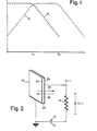
- Curve 10 in Figure 1 - is a plot of the logarithm of the res p on- sivity of a typical thermistor bolometer versus the logarithm of the frequency of a sinusoidally modulated incident radiation power to be detected. Curve 10 shows the responsitivity remaining fairly constant up to the thermal relaxation frequency. Above this frequency the responsitivity drops off quickly.
- Curve 12 of Figure 1 shows a plot of the logarithm of the resonpsivity of a typical pyroelectric detector versus the logarithm of the frequency of a sinusoidally modulated incident radiation power to be detected.
- w c which is determined by the electronic time constant of the circuit
- the responsivity of the pyroelectric detector is relatively flat.
- the responsivity of the pyroelectric detector quickly drops off.
- Miller et al disclose a pyroelectric field effect radiation detector.
- the pyroelectric material is electrically connected in series with a source of voltage (e.g. poling circuit 44) and with a load resistance (e.g. the resistance across the source and gate of the FET).
- a source of voltage e.g. poling circuit 44
- a load resistance e.g. the resistance across the source and gate of the FET.
- thermoelectric detectors Many materials are known which can be used as the sensing elements of thermistor bolometers, and many materials are known which can be used as pyroelectric detectors. Within these two classes of materials is a single subset of materials which exhibit both thermistor and pyroelectric properties. That is, the materials in this subset exhibit both changes in their electrical resistance with changes in temperature, and change in their spontaneous electrical polarization with changes in temperature.
- Known pyroelectric materials whose electrical conductivity is strongly temperature dependent include single crystals of boracites, sodium nitrite (NaNO )y tin-hypothiodiphos p hate (Sn 2 P 2 S 6 ), lead germanate (Pb 5 Ge 3 O 11 ), lithium ammonium sulfate (LiNH 4 SO 4 ), and some ferroelectric ceramics.
- a unique broadband infrared thermal detector comprises a combined thermistor bolometer and a pyroelectric detector.
- the frequency response of this "Pyroelectric Thermistor Bolometer” is the combination of the frequency responses of a thermistor bolometer and a pyroelectric detector.
- PTB Pulse Thermistor Bolometer
- the PTB can yield high sensitivity at frequencies both above and below the thermal relaxation frequency.
- the PTB can yield a flat frequency response over a boradband from dc (0 Hertz) to a high frequency determined by the electronic time constant of the PTB circuit.
- An infrared thermal detector comprises an infrared thermal sensing element, a load resistor, and a voltage source.
- the thermal sensing element comprises a pyroelectric material whose electrical conductivity changes with temperature.
- the sensing element has two substantially planar surfaces on which first and second electrodes are provided opposite each other.
- the load resistor has first and second electrodes one of which is electrically connected to an electrode of the sensing element.
- the voltage source is then connected to the remaining electrodes of the sensing element'.and the load resistor.
- the circuit is provided with variable voltage supply means, or a variable load resistor, or both.
- the load resistor and bias voltage are then adjusted (or they are initially chosen) so that at the "equilibrium" temperature of operation of the sensing element, the PTB constant, k, (defined below) is greater than zero.
- k is between 0.1 and 5.
- k is approximately equal to one.
- the PTB need not be provided with a variable voltage or a variable resistor if the values of the applied voltage and the load resistor are initially chosen so that at the temperature of operation of the PTB, k > O.
- the polarity of the voltage source must be chosen so that the pyroelectric component and the thermistor component of the PTB signal, due to a given change in temperature, are of the same sign (positive or negative). This means that when the spontaneous electric polarization decreases with increasing temperature, and the electrical resistance decreases with increasing temperature, the bias voltage should generate an electric field having a component which is directed opposite the spontaneous polarization. With small bias voltages and materials having high coercive fields, there is little danger of depoling the material (if it is operated far from its Curie Point).
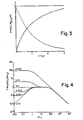
- a pyroelectric thermistor bolometer according to the invention is shown in Figure 2.
- the detector includes a PTB sensing element 14, a load resistor 16, and a voltage source 18.
- Load resistor 16 and voltage source 1 8 may be either fixed or variable. Their operational values can be selected in accordance with the criteria which are discussed further below. Both of these elements of the invention are conventional electronic parts, and are readily available.
- the PTB sensing element comprises a pyroelectric material 20 whose electrical conductivity changes with temperature.
- pyroelectric materials in which the electrical conductivity is strongly temperature dependent are crystals of boracites, sodium nitride, tin-hypothiodiphosphate, lead germanate, lithium ammonium sulfate, and some ferro-electric ceramics.
- the invention was actually constructed utilizing a copper-chloride boracite crystal. However, it is believed that less expensive materials, such as ferroelectric ceramics or tin-hypothiodiphosphate, would be preferable to the copper-chloride boracite.
- All pyroelectric materials have a pyroelectric ixis along which they are spontaneously polarized.
- the spontaneous polarization at any part of the material may be in either of the two opposite directions along this axis.
- the pyroelectric material must have a net polarization (arrow 22) in one direction (pointing within the material from the negative end of the net dipole moment to the positive end thereof).
- the pyroelectric material 20 is provided with electrodes 24 on opposite planar faces of the pyroelectric material.
- the electrodes are oriented transverse to the pyroelectric axis.
- the electrodes in Figure 2 are perpendicular to the pyroelectric axis.
- a first electrode of the PTB sensing element 14 is then connected to a first electrode on the load resistor 16.
- the voltage source 18 is then connected to the remaining electrodes of the sensing element 14 and the load resistor 16.
- the polarity of the voltage source 18 depends upon the direction of polarization, the sign of the pyroelectric coefficient, and the sign of the temperature coefficient of resistance of the PTB sensing element 14.
- the polarity of voltage source 18 must be chosen so that for a given change in temperature of the PTB sensint element 14, both the pyroelectric effect and the thermistor effect will tend to either increase or decrease the circuit current. That is, for a given change in temperature, both the pyroelectric effect and the thermistor effect should reinforce each other, rather than oppose each other.
- the polarity of voltage source 18 should generate an electric field across the PTB sensing element 14 which is directed opposite to the direction of spontaneous polarization of the sensing element. This is shown in Figure 2 where the net polarization direction is shown by arrow 22, and the polarity of voltage source 18 generates an electric field pointing in a direction shown by arrow 26.
- the radiation power absorbed in the PTB sensing element as a function of time, t is given by the function W(t).
- W(t) the thermal power being absorbed by the sensing element
- the dissipation constant is the thermal conductivity between the sensing element and its surroundings).
- G ⁇ T power dissipated.
- a positive pyroelectric coefficient means that the polarization decreases with increasing temperature.
- a positive pyroelectric coefficient means that the polarization increases with increasing temperature.
- a rise in temperature d( ⁇ T) produces a change, dR, in resistance, R, of where R is the resistance of the thermistor at the tem- perature of the surrounding environment, and ⁇ is the temperature coefficient of resistance (which is substantially constant for the small changes in temperature which we have assumed, above).
- dR in resistance
- R the resistance of the thermistor at the tem- perature of the surrounding environment
- ⁇ the temperature coefficient of resistance
- the total circuit current can be derived by separately calculating the conduction current and the displacement current through the PTB sensing element. From this, the time-varying circuit current can be computed.
- the conduction current, I through the PTB is where R is the electrical resistance of the PTB.
- the dielectric constant, ⁇ , of the PTB sensing element is equal to ( ⁇ o + ), and the pyroelectric coefficient, p. is equal to . Therefore
- Equation (5) reduces to Thus second order term (both ⁇ V and ⁇ T change with changes in the input radiation) so .
- ⁇ e is the RC time constant of the pyro- electric circuit. This is the same electronic time constant which would appear in the analysis of a pyroelectric detector which does not also operate, according to the invention, as a PTB. Moreover, the thermal time constant in equation (2) is the same constant which would appear in the analysis of either a pyroelectric detector or a thermistor bolometer, neither of which also operate as a PTB.
- ⁇ is the charge per degree due to a change in polarization divided by the current per degree due to a change in resistance.
- ⁇ reflects the relative contributions to the output signal of the pyroelectric effect and the thermistor effect.
- ⁇ V(t) The response, ⁇ V(t), as a function of time is plotted in Figure 3, together with the separate contributions of the pyroelectric and thermistor components of the output signal.
- the fast rise of the step response to a steady value is an outstanding trait of the PTB.
- the steady state response of the circuit shown in Figure 2 to a sinusoidal input of frequency ⁇ is also a sinusoid of frequency ⁇ .
- the ratio of the amplitude of the response to that of the input is the magnitude of the transfer function H(s) when j ⁇ is substituted for s.
- the responsivity r( ⁇ ) of the PTB is given by
- the responsivity is normalized by dividing it by and the frequency is normalized by multiplying it by ⁇ T , so that the graph is independent of the actual values of these paramters.
- Figure 4 shows that the PTB acts as a pyroelectric detector and maximum responsivity is obtained at frequencies smaller than and larger than .
- the PTB acts as a thermistor and maximum response is obtained at frequencies smaller than .
- a thin slice of a copper-chloride boracite (Cu 3 B 7 O 13 Cl) crystal was prepared having a thickness of 60 microns and a cross-sectional area of 0.04 square centimeters.
- the faces of the slice were perpendicular to the pyroelectric axis and were covered with gold electrodes.
- the electrodes were provided by vapor deposition.
- Attached to the gold electrodes were 75 micron diameter silver leads from which the crystal was suspended.
- One silver lead was connected to a lead of a 50 megohm load resistor.
- the other silver lead was connected to a variable voltage source. The remaining terminals of the resistor and voltage source were connected to each other.
- Oscillogram ( e ) shows the voltage response for a bias voltage greater than that in (d).
- the thermistor signal component rises above the pyroelectric signal component, and the circuit approaches a thermistor bolometer.
Landscapes
- Engineering & Computer Science (AREA)
- Power Engineering (AREA)
- Physics & Mathematics (AREA)
- General Physics & Mathematics (AREA)
- Spectroscopy & Molecular Physics (AREA)
- Radiation Pyrometers (AREA)
- Photometry And Measurement Of Optical Pulse Characteristics (AREA)
Applications Claiming Priority (2)
| Application Number | Priority Date | Filing Date | Title |
|---|---|---|---|
| US06/442,804 US4501967A (en) | 1982-11-18 | 1982-11-18 | Broad band pyroelectric infrared detector |
| US442804 | 1989-11-29 |
Publications (3)
| Publication Number | Publication Date |
|---|---|
| EP0109712A2 true EP0109712A2 (de) | 1984-05-30 |
| EP0109712A3 EP0109712A3 (en) | 1984-12-05 |
| EP0109712B1 EP0109712B1 (de) | 1987-08-19 |
Family
ID=23758211
Family Applications (1)
| Application Number | Title | Priority Date | Filing Date |
|---|---|---|---|
| EP83201624A Expired EP0109712B1 (de) | 1982-11-18 | 1983-11-15 | Thermischer Detektor für das Infrarotgebiet |
Country Status (5)
| Country | Link |
|---|---|
| US (1) | US4501967A (de) |
| EP (1) | EP0109712B1 (de) |
| JP (1) | JPS59105528A (de) |
| CA (1) | CA1225720A (de) |
| DE (1) | DE3373137D1 (de) |
Cited By (1)
| Publication number | Priority date | Publication date | Assignee | Title |
|---|---|---|---|---|
| FR2595025A1 (fr) * | 1986-02-25 | 1987-08-28 | Thomson Csf | Detecteur d'images a memoire |
Families Citing this family (6)
| Publication number | Priority date | Publication date | Assignee | Title |
|---|---|---|---|---|
| LU86269A1 (fr) * | 1986-01-28 | 1987-09-03 | Labofina Sa | Procede pour enlever les cires des gasoils |
| US4875029A (en) * | 1987-12-30 | 1989-10-17 | Aritech Corporation | Suppressed transient uniform detection sensitivity pir detector |
| DE3820619A1 (de) * | 1988-06-17 | 1989-12-21 | Fraunhofer Ges Forschung | Vorrichtung zur messung der strahlungsleistung von lasern |
| JPH11344377A (ja) | 1998-06-02 | 1999-12-14 | Matsushita Electric Ind Co Ltd | 赤外線検知素子およびその製造方法 |
| US7164131B2 (en) * | 2005-05-26 | 2007-01-16 | Phelan Jr Robert Joseph | High fidelity electrically calibrated pyroelectric radiometer |
| CA3048649A1 (en) | 2017-01-13 | 2018-07-19 | The Research Foundation For The State University Of New York | Chopped passive infrared sensor apparatus and method for stationary and moving occupant detection |
Family Cites Families (7)
| Publication number | Priority date | Publication date | Assignee | Title |
|---|---|---|---|---|
| US3571592A (en) * | 1968-08-01 | 1971-03-23 | Bell Telephone Labor Inc | Pyroelectric devices of high acoustic loss showing increased frequency response |
| SE376798B (de) * | 1970-05-07 | 1975-06-09 | Western Electric Co | |
| US3748624A (en) * | 1971-03-30 | 1973-07-24 | Nippon Denso Co | Pyrometric sensor using thermistor |
| US4024560A (en) * | 1975-09-04 | 1977-05-17 | Westinghouse Electric Corporation | Pyroelectric-field effect electromagnetic radiation detector |
| US4044251A (en) * | 1976-05-18 | 1977-08-23 | Minnesota Mining And Manufacturing Company | Electromagnetic radiation detector with large area sensing medium |
| JPS54151882A (en) * | 1978-05-22 | 1979-11-29 | Kureha Chemical Ind Co Ltd | Method of pyroelectrically detecting infrared rays with polyvinylidene fluoride |
| FR2501901A1 (fr) * | 1981-03-13 | 1982-09-17 | Commissariat Energie Atomique | Detecteur pyroelectrique a facteur de merite optimise |
-
1982
- 1982-11-18 US US06/442,804 patent/US4501967A/en not_active Expired - Fee Related
-
1983
- 1983-11-15 EP EP83201624A patent/EP0109712B1/de not_active Expired
- 1983-11-15 DE DE8383201624T patent/DE3373137D1/de not_active Expired
- 1983-11-17 CA CA000441368A patent/CA1225720A/en not_active Expired
- 1983-11-18 JP JP58216437A patent/JPS59105528A/ja active Granted
Cited By (3)
| Publication number | Priority date | Publication date | Assignee | Title |
|---|---|---|---|---|
| FR2595025A1 (fr) * | 1986-02-25 | 1987-08-28 | Thomson Csf | Detecteur d'images a memoire |
| EP0236206A1 (de) * | 1986-02-25 | 1987-09-09 | Thomson-Csf | Bilddetektor mit Gedächtnis |
| US4782227A (en) * | 1986-02-25 | 1988-11-01 | Thomson-Csf | Image sensor with memory |
Also Published As
| Publication number | Publication date |
|---|---|
| JPS59105528A (ja) | 1984-06-18 |
| CA1225720A (en) | 1987-08-18 |
| DE3373137D1 (en) | 1987-09-24 |
| EP0109712B1 (de) | 1987-08-19 |
| EP0109712A3 (en) | 1984-12-05 |
| JPH038698B2 (de) | 1991-02-06 |
| US4501967A (en) | 1985-02-26 |
Similar Documents
| Publication | Publication Date | Title |
|---|---|---|
| US6316770B1 (en) | Thermal detector with bolometric effect amplification | |
| US7564021B2 (en) | Pyroelectric sensor | |
| US6339221B1 (en) | Ferroelectric thermometry and pyrometry by active operation | |
| Beerman | The pyroelectric detector of infrared radiation | |
| US4147562A (en) | Pyroelectric detector | |
| Hashimoto et al. | Si monolithic microbolometers of ferroelectric BST thin film combined with readout FET for uncooled infrared image sensor | |
| EP0109712B1 (de) | Thermischer Detektor für das Infrarotgebiet | |
| Ivill et al. | Method and characterization of pyroelectric coefficients for determining material figures of merit for infrared (IR) detectors | |
| US3453887A (en) | Temperature change measuring device | |
| Whatmore | Characterisation of pyroelectric materials | |
| US4935626A (en) | Broadband superconducting detector having a thermally isolated sensing element | |
| US6437331B1 (en) | Bolometer type infrared sensor with material having hysterisis | |
| US3398281A (en) | Direct reading, wavelength independent radiometer employing a pyroelectric crystal detector | |
| US7687775B2 (en) | Ferroelectric infrared detector and method | |
| Tiffany | Introduction and review of pyroelectric detectors | |
| Poberaj et al. | Pyroelectric effect measurements in YBa2Cu3O6+ y and La2CuO4 materials | |
| Lavi et al. | Pyroelectric response to single infrared laser pulses in triglycine sulphate and strontium‐barium niobate | |
| Kuwano et al. | The Pyroelectric Sensor | |
| Pfafman et al. | Pyroelectric microcalorimetry | |
| JPH06109536A (ja) | 赤外線測定装置 | |
| Ullman et al. | Pyroelectric detection properties of gadolinium molybdate (gmo) | |
| JPS6332328A (ja) | 焦電型赤外線センサ | |
| Lang | Use of pyroelectric devices for measuring small temperature changes | |
| Chirtoc et al. | Induced pyroelectric effect in the paraelectric phase of some ceramic materials and applications | |
| SU709957A1 (ru) | Способ измерени мощности импульсного излучени |
Legal Events
| Date | Code | Title | Description |
|---|---|---|---|
| PUAI | Public reference made under article 153(3) epc to a published international application that has entered the european phase |
Free format text: ORIGINAL CODE: 0009012 |
|
| AK | Designated contracting states |
Designated state(s): DE FR GB NL |
|
| PUAL | Search report despatched |
Free format text: ORIGINAL CODE: 0009013 |
|
| AK | Designated contracting states |
Designated state(s): DE FR GB NL |
|
| 17P | Request for examination filed |
Effective date: 19850313 |
|
| 17Q | First examination report despatched |
Effective date: 19860325 |
|
| GRAA | (expected) grant |
Free format text: ORIGINAL CODE: 0009210 |
|
| AK | Designated contracting states |
Kind code of ref document: B1 Designated state(s): DE FR GB NL |
|
| REF | Corresponds to: |
Ref document number: 3373137 Country of ref document: DE Date of ref document: 19870924 |
|
| ET | Fr: translation filed | ||
| PLBE | No opposition filed within time limit |
Free format text: ORIGINAL CODE: 0009261 |
|
| STAA | Information on the status of an ep patent application or granted ep patent |
Free format text: STATUS: NO OPPOSITION FILED WITHIN TIME LIMIT |
|
| 26N | No opposition filed | ||
| PGFP | Annual fee paid to national office [announced via postgrant information from national office to epo] |
Ref country code: GB Payment date: 19931029 Year of fee payment: 11 |
|
| PGFP | Annual fee paid to national office [announced via postgrant information from national office to epo] |
Ref country code: FR Payment date: 19931124 Year of fee payment: 11 |
|
| PGFP | Annual fee paid to national office [announced via postgrant information from national office to epo] |
Ref country code: NL Payment date: 19931130 Year of fee payment: 11 |
|
| PGFP | Annual fee paid to national office [announced via postgrant information from national office to epo] |
Ref country code: DE Payment date: 19940127 Year of fee payment: 11 |
|
| PG25 | Lapsed in a contracting state [announced via postgrant information from national office to epo] |
Ref country code: GB Effective date: 19941115 |
|
| PG25 | Lapsed in a contracting state [announced via postgrant information from national office to epo] |
Ref country code: NL Effective date: 19950601 |
|
| GBPC | Gb: european patent ceased through non-payment of renewal fee |
Effective date: 19941115 |
|
| NLV4 | Nl: lapsed or anulled due to non-payment of the annual fee | ||
| PG25 | Lapsed in a contracting state [announced via postgrant information from national office to epo] |
Ref country code: FR Effective date: 19950731 |
|
| REG | Reference to a national code |
Ref country code: FR Ref legal event code: ST |
|
| PG25 | Lapsed in a contracting state [announced via postgrant information from national office to epo] |
Ref country code: DE Effective date: 19951201 |