EP0109686B1 - Color sensor - Google Patents
Color sensor Download PDFInfo
- Publication number
- EP0109686B1 EP0109686B1 EP83111612A EP83111612A EP0109686B1 EP 0109686 B1 EP0109686 B1 EP 0109686B1 EP 83111612 A EP83111612 A EP 83111612A EP 83111612 A EP83111612 A EP 83111612A EP 0109686 B1 EP0109686 B1 EP 0109686B1
- Authority
- EP
- European Patent Office
- Prior art keywords
- light
- light emitting
- color
- color sensor
- sensor according
- Prior art date
- Legal status (The legal status is an assumption and is not a legal conclusion. Google has not performed a legal analysis and makes no representation as to the accuracy of the status listed.)
- Expired
Links
Images
Classifications
-
- G—PHYSICS
- G01—MEASURING; TESTING
- G01J—MEASUREMENT OF INTENSITY, VELOCITY, SPECTRAL CONTENT, POLARISATION, PHASE OR PULSE CHARACTERISTICS OF INFRARED, VISIBLE OR ULTRAVIOLET LIGHT; COLORIMETRY; RADIATION PYROMETRY
- G01J3/00—Spectrometry; Spectrophotometry; Monochromators; Measuring colours
- G01J3/02—Details
-
- G—PHYSICS
- G01—MEASURING; TESTING
- G01J—MEASUREMENT OF INTENSITY, VELOCITY, SPECTRAL CONTENT, POLARISATION, PHASE OR PULSE CHARACTERISTICS OF INFRARED, VISIBLE OR ULTRAVIOLET LIGHT; COLORIMETRY; RADIATION PYROMETRY
- G01J3/00—Spectrometry; Spectrophotometry; Monochromators; Measuring colours
- G01J3/02—Details
- G01J3/0205—Optical elements not provided otherwise, e.g. optical manifolds, diffusers, windows
- G01J3/0218—Optical elements not provided otherwise, e.g. optical manifolds, diffusers, windows using optical fibers
-
- G—PHYSICS
- G01—MEASURING; TESTING
- G01J—MEASUREMENT OF INTENSITY, VELOCITY, SPECTRAL CONTENT, POLARISATION, PHASE OR PULSE CHARACTERISTICS OF INFRARED, VISIBLE OR ULTRAVIOLET LIGHT; COLORIMETRY; RADIATION PYROMETRY
- G01J3/00—Spectrometry; Spectrophotometry; Monochromators; Measuring colours
- G01J3/46—Measurement of colour; Colour measuring devices, e.g. colorimeters
- G01J3/50—Measurement of colour; Colour measuring devices, e.g. colorimeters using electric radiation detectors
-
- G—PHYSICS
- G01—MEASURING; TESTING
- G01J—MEASUREMENT OF INTENSITY, VELOCITY, SPECTRAL CONTENT, POLARISATION, PHASE OR PULSE CHARACTERISTICS OF INFRARED, VISIBLE OR ULTRAVIOLET LIGHT; COLORIMETRY; RADIATION PYROMETRY
- G01J3/00—Spectrometry; Spectrophotometry; Monochromators; Measuring colours
- G01J3/46—Measurement of colour; Colour measuring devices, e.g. colorimeters
- G01J3/50—Measurement of colour; Colour measuring devices, e.g. colorimeters using electric radiation detectors
- G01J3/501—Colorimeters using spectrally-selective light sources, e.g. LEDs
-
- G—PHYSICS
- G01—MEASURING; TESTING
- G01J—MEASUREMENT OF INTENSITY, VELOCITY, SPECTRAL CONTENT, POLARISATION, PHASE OR PULSE CHARACTERISTICS OF INFRARED, VISIBLE OR ULTRAVIOLET LIGHT; COLORIMETRY; RADIATION PYROMETRY
- G01J3/00—Spectrometry; Spectrophotometry; Monochromators; Measuring colours
- G01J3/46—Measurement of colour; Colour measuring devices, e.g. colorimeters
- G01J2003/466—Coded colour; Recognition of predetermined colour; Determining proximity to predetermined colour
-
- G—PHYSICS
- G01—MEASURING; TESTING
- G01N—INVESTIGATING OR ANALYSING MATERIALS BY DETERMINING THEIR CHEMICAL OR PHYSICAL PROPERTIES
- G01N21/00—Investigating or analysing materials by the use of optical means, i.e. using sub-millimetre waves, infrared, visible or ultraviolet light
- G01N21/17—Systems in which incident light is modified in accordance with the properties of the material investigated
- G01N21/25—Colour; Spectral properties, i.e. comparison of effect of material on the light at two or more different wavelengths or wavelength bands
- G01N21/31—Investigating relative effect of material at wavelengths characteristic of specific elements or molecules, e.g. atomic absorption spectrometry
- G01N21/314—Investigating relative effect of material at wavelengths characteristic of specific elements or molecules, e.g. atomic absorption spectrometry with comparison of measurements at specific and non-specific wavelengths
-
- G—PHYSICS
- G01—MEASURING; TESTING
- G01N—INVESTIGATING OR ANALYSING MATERIALS BY DETERMINING THEIR CHEMICAL OR PHYSICAL PROPERTIES
- G01N2201/00—Features of devices classified in G01N21/00
- G01N2201/06—Illumination; Optics
- G01N2201/069—Supply of sources
- G01N2201/0696—Pulsed
-
- G—PHYSICS
- G01—MEASURING; TESTING
- G01N—INVESTIGATING OR ANALYSING MATERIALS BY DETERMINING THEIR CHEMICAL OR PHYSICAL PROPERTIES
- G01N2201/00—Features of devices classified in G01N21/00
- G01N2201/08—Optical fibres; light guides
Definitions
- the present invention relates to a color sensor for recognizing the hue of articles by sensing rays of light passed through or reflected from the articles.
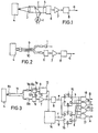
- Fig. 1 shows an example of a conventional color sensor, as known from practice, for recognizing color of articles.
- rays of white light are emitted from a light source 1 made of a tungsten lump and a part of the rays of light is reflected by a half mirror 2.
- the light reflected by the half mirror 2 is collimated by a lens 3 at a position at which an article or an object 4 to be recognized is placed.
- Each of the objects is colored by a specific color by the color of the material forming the object or by a label or mark attached on the surface of the object.
- the light reflected by the object is changed into a parallel light by the lens 3 and is received by a photo sensing unit 6 through the half mirror 2 and a color filter 5.
- the color filter 5 has a specific spectral characteristic of transparency corresponding to the desired hue or color of the object that allows to pass the light of the color of the object.
- the output signal of the photo sensing unit 6 is amplified by an amplifier 7 and in turn applied to a comparator 8.
- the output signal of the amplifier 7 is compared with a reference voltage applied to the one input terminal of the comparator 8, which produces a high level output (referred to as 1 hereinafter) or a low level output (referred to as 0 hereinafter) depending on whether or not the output level of the amplifier 7 exceeds the reference voltage, so that a digital signal (a) can be obtained.
- the contents of the digital signal (a) i.e., 1 or 0 represent whether or not the photo sensing unit 6 receives the reflected light, accordingly the content of the digital signal (a) represents the hue of the object.
- Fig. 2 is another example of a conventional color sensor and the reference numerals 9 and 10 show optical fibers respectively.
- like parts in Fig. 1 are designated by the same reference numerals.
- a light emitting diode is used as the light source 1 and the light of the light source 1 is projected on the object 4 through the optical fiber 9.
- the light reflected by the object 4 is passed through the optical fiber 10 and received by the photo sensing unit 6.
- the light source illuminates the light of the desired color so that the filter 5 provided in the color sensor in Fig. 1 can be omitted and the area of the light emitting port of the optical fiber can be minimized and furthermore the light emitting port can be placed at very near the object so that the radius of spot light incident to the object can be minimized, thereby enabling either to minimize the total size of the color sensor per se as compared to the color sensor shown in Fig. 1 and to recognize the color of the object of small size.
- the conventional color sensors as described above are not applicable to recognize more than three colors since the recognizable color in the conventional color sensors is limited by the color of the filter 5 or the color of the light emitting diode 1. For example, when a red color filter or the red light emitting diode is used, the color sensor can recognize only whether the color of the object is red or not.
- One way of recognizing more than three colors of the objects is to provide an arrangement for interchanging a plurality of filters of various kinds of colors in place of the color filter 5 in Fig. 1. For example, assuming that objects each having one of the four colors of such as red, green, yellow and other colors are to be classified, red objects are classified using a red filter, subsequently green objects are classified using the green filter. The same operation is performed using the yellow filter and other color filter to classify the yellow objects and other color objects so that the objects can be classified into four colors.
- Another method of classifying the color of the objects having more that three colors is to provide a plurality of color sensors for each of the colors to be classified. For example, if there are four colors to be classified, four color sensors each having different color filter are employed. This method is effective to decrease the time for classifying the objects into four colors by placing each of the color sensors along the line of flow of the objects.
- the number of color sensors used increases as the number of the colors to be classified increases.
- the respective color sensors must have a uniform sensing characteristics.
- the precharacterizing part of Claim 1 refers to a color sensor as described in DE-A-25 07 162.
- the known color sensor is operating in a time divisional manner.
- the light received by a light receiver is distributed on several circuits each of which contains a comparator.
- the output signals of said comparators are analogous signals which are fed through analogue gates pulse shaping circuits.
- a combination circuit forms from both voltages produced by the pulse shaping circuits a total voltage which is used as a reference voltage for the comparators.
- the operations of the circuits of the color sensor are generally analogue hues.
- the separated analogue color signals are added together and the circuit for evaluating the hue becomes very complicated and the possibility of an error in the color detection is high.
- each of the light emitting sources 1a and 1 b is driven to emit the red light and the green light alternately by a time divisional drive circuit 13 in a time divisional manner.
- a light transmission path 11 is formed by a plurality of optical fibers bundled together with a part of the one end of bundled optical fibers of the light transmission path 11 opposed adjacent to the light emitting sources 1 a and 1 b to form a light entrance 11 a to which the light from the light emitting sources 1 a and 1 b is entered and the remaining part of the said one end of the optical fibers opposed to the photo receiving unit 6 to form a light exit 11 b to project the light reflected from the object 4 on the photo sensing unit 6.
- the other ends of the part of the optical fibers forming the light entrance 11 a are disposed to face the object 4 to form the light exit 11c of light to project the light of the light emitting sources 1 a and 1 b on the object 4.
- the other ends of the remaining part of the optical fibers forming the light exit 11 b for the photo sensing unit 6 are disposed to face the object 4 to form the light entrance 11c for receiving the light reflected from the object 4.
- the respective optical fibers EX for receiving the light and the optical fibers PR for projecting the light are distributed alternately as shown in Fig. 5 to receive or project the light uniformly overall the area of the end 11c.
- the photo sensing unit 6 is formed by a single photo transistor to produce an analog signal corresponding to the quantity of the incident light to the photo transistor.
- the comparator 8 is applied with a reference voltage at one of the input terminals and compares the analog signal applied to another input terminal from the amplifier 7 with the reference voltage to provide an output of 1 or 0 depending on whether or not the analog signal exceeds the reference voltage.
- Two flip-flops 15 and 16 of D type receive the output of the comparator 8, i.e. the digital signal e to hold thereof at the timing when every strobe pulses f, g are applied.
- the flip-flops 15 and 16 form a signal holding circuit.
- AND gates 17, 18, 19 and 20 form a logic circuit to calculate a logic of recognizing the colors of the object on the basis of the level of the digital signal e held in the hold circuit.
- a timing circuit 14 supplies timing signals to the time divisional drive circuit 13, which produces drive current a and b to drive the light emitting sources 1a and 1b with a phase difference of 180° and period of To with a duty ratio of 50%.
- both of the light emitting sources 1a and 1 b emit the red light and the green light alternately, whereby the red light and the green light are projected on the object 4 in a time divisional manner passing through the entrance 11 a and the light transmission path 11.
- the periods during which the light emitting source 1a emits the light are designated by t 1 through t 3 , t 5 through t, and the period during which the light emitting source 1b emits the light is designated by t 3 through t 5 .
- the object 4 illuminated reflects the light of a color corresponding to the color of the surface of the object and the reflected light passes the exit 11c and the light transmission path 11 and is received by the photo sensing unit 6, which is producing an analog signal of a large amplitude when the reflected light is received. As. shown in Fig.
- the amplitude of the analog signal of the output of the photo sensing unit 6 becomes large in the time periods t 1 through t 3 , t 5 through t 7 during which the light emitting source 1a emits the light since the object 4 reflects the red light and absorbs the green light, and the amplitude becomes small in the period t 3 through t 5 during which the light emitting source 1b emits the light.
- the analog signal from the photo sensing unit 6 is amplified by the amplifier 7 to produce the analog signal d of the predetermined amplitude and is fed to the comparator 8 to be compared with the reference voltage Vs.
- the comparator 8 produces the digital signals e, the level of which is 1 in the periods t, through t 3 and t 5 through t 7 during which the amplitude of the analog signal is large and is 0 in the period t 3 through t 5 during which the amplitude of the analog signal is small.
- the digital signals produced by the comparator 8 are fed to the D input terminals of the flip-flops 15 and 16 which receive the strobe pulses f and g at the T input terminals from the timing pulse generator 14.
- the D type flip-flop 15 holds the level of the digital signal e at the time of the positive edge of each of the strobe pulses f and the D type flip-flop 16 holds the level of the digital signal e at the positive edges of each of the strobe pulses g.
- the output of the D type flip-flop 15 becomes 1 upon receipt of the strobe pulse f at the timing t 2 in the periods of t, through t 3 thereby the Q output thereof being 1 with the Q output being 0.
- the 1 level of the Q output of the flip-flop 15 shows the object 4 has red color and the 1 level is held by the next positive edge of the strobe pulse f.
- the Q output of the D type flip-flop 16 becomes 0 upon receipt of the positive edge of the strobe pulse g at the timing t 4 in the period t 3 through t 5 with the Q output of thereof being 1.
- the 0 level of the D type flip-flop 16 shows that the photo sensing unit 6 does not receive the green light and the 0 level is held until the next strobe pulse g is applied.
- the table 1 shows the relation of the output of flip-flops 15 and 16 and the absence or presence of the light of the respective colors incident to the photo sensing unit 6.
- the AND gates 17, 18, 19 and 20 judges the states of the flip-flops 15 and 16 to generate signals representing the hue of the objects. As shown in Fig. 3, the AND gate 18 receives the output signals h and k, the AND gate 19 receives the output signals i and j, and the AND gate 17 receives the output signals i and k.
- the timings of the light emission by the light emitting sources 1a a and 1b are shifted by T o /2 each other, as the timings of the strobe pulses f and g are also shifted by T o /2 and the state of the output of the D type flip-flop 15 can be held until the another flip-flop 16 reads in the output of the comparator 8 upon receipt of the strobe pulse g, the AND gates 17 through 20 receive the signals h, i, j, and k simultaneously.
- Y is the period for holding the output of the comparator 8
- X is the period for judging the state of the output of the flip-flops.
- the four kinds of hues can be recognized or classified by using only two color light emitting sources and the recognition of the hue can be made in the real time basis.
- the currents of the light emitting diodes 1 a and 1 b are so adjusted that the intensity of the lights of the light emitting diodes 1 a and 1 b is equal.
- the reference voltage of the comparator 8 is set to recognize the yellow by setting the reference voltage in such a manner that the comparator 8 generates 1 in both cases when the red light is illuminated and when the green light is illuminated.
- the path can be separated two paths 9 and 10 as shown in Fig. 2 one for illuminating the light on the object and another for receiving the reflected light from the object.
- Fig. 7 shows the third embodiment of the color sensor according to the present invention wherein the light entrance 11a of the color sensor shown in Fig. 3 is connected with a light emitting unit 20 having a box-like enclosure 21 made of an opaque material.
- the light emitting source 1a and 1b are respectively fixed to one face 21a of the enclosure 21 with the light emitting faces of the light emitting sources 1 a and 1 b directed to the opposite face 21 b on which the light sntrance 11a of the light transmission path 11 is connected.
- the enclosure 21 is separated by a light diffuser 22 such as a sheet of frosted glass disposed between the both faces 21a and 21b.
- the light emitted from the light emitting source 1a and/or 1 b is diffused by the light duffuser 22 and in turn the diffused light enters the light entrance 11a.
- directionality of the light emitting sources such as light emitting diodes can be broadened so that the intensity of the light entering the light entrance 11a from both of the light emitting sources 1a a and 1 becomes uniform.
- the color recognition operation is similar to the arrangement shown in Fig. 3.
- hemispherical enclosure 30 may be used as shown in Fig. 8.
- the light emitting diodes 1a and 1b are mounted on the flat face of the enclosure 30 which is filled with a light diffusing material.
- the light entrance 11 a of the light transmission path 11 is disposed to oppose the apex 30a of the hemispherical portion of the enclosure 30.
- GaAIAs diode 1a for the red light and GaAs:Si diode 1b for the infra red light may be used.
- anti-Stokes fluorescent material 31 may be filled in the enclosure uniformly, so that green light may be emitted by the infra red light emitted from the light source 1 b.
- the shape of the enclosure is not limited to the hemispherical shape, in case of the hemispherical shape, quantity of the light entering the light transmission path may be increased.
- the GaAs:Si diode 41, the layer 40 and the flat face of the enclosure 42 may be adhered integrally.
- the enclosure 42 acts as a lens to collimate both of the lights from the diodes 1a and 41 to the light entrance 11a.
- the bundled optical fibers with the end portions PR and EX thereof so uniformly distributed as shown in Fig. 5 may be used for the color sensor having one color light emitting source 1 as shown in Fig. 11.
Landscapes
- Physics & Mathematics (AREA)
- Spectroscopy & Molecular Physics (AREA)
- General Physics & Mathematics (AREA)
- Spectrometry And Color Measurement (AREA)
- Geophysics And Detection Of Objects (AREA)
Description
- The present invention relates to a color sensor for recognizing the hue of articles by sensing rays of light passed through or reflected from the articles.
- In order to classify a desired kind of articles from various kinds of articles in a manufacturing process, it is well known to use a method of recognizing the hue or color of the articles or objects.
- Fig. 1 shows an example of a conventional color sensor, as known from practice, for recognizing color of articles. Referring to Fig. 1, rays of white light are emitted from a
light source 1 made of a tungsten lump and a part of the rays of light is reflected by ahalf mirror 2. The light reflected by thehalf mirror 2 is collimated by a lens 3 at a position at which an article or anobject 4 to be recognized is placed. Each of the objects is colored by a specific color by the color of the material forming the object or by a label or mark attached on the surface of the object. The light reflected by the object is changed into a parallel light by the lens 3 and is received by aphoto sensing unit 6 through thehalf mirror 2 and a color filter 5. The color filter 5 has a specific spectral characteristic of transparency corresponding to the desired hue or color of the object that allows to pass the light of the color of the object. The output signal of thephoto sensing unit 6 is amplified by anamplifier 7 and in turn applied to acomparator 8. The output signal of theamplifier 7 is compared with a reference voltage applied to the one input terminal of thecomparator 8, which produces a high level output (referred to as 1 hereinafter) or a low level output (referred to as 0 hereinafter) depending on whether or not the output level of theamplifier 7 exceeds the reference voltage, so that a digital signal (a) can be obtained. The contents of the digital signal (a) i.e., 1 or 0 represent whether or not thephoto sensing unit 6 receives the reflected light, accordingly the content of the digital signal (a) represents the hue of the object. - Fig. 2 is another example of a conventional color sensor and the
reference numerals 9 and 10 show optical fibers respectively. In Fig. 2 like parts in Fig. 1 are designated by the same reference numerals. In this conventional color sensor, a light emitting diode is used as thelight source 1 and the light of thelight source 1 is projected on theobject 4 through the optical fiber 9. The light reflected by theobject 4 is passed through theoptical fiber 10 and received by thephoto sensing unit 6. - According to the color sensor shown in Fig. 2, the light source illuminates the light of the desired color so that the filter 5 provided in the color sensor in Fig. 1 can be omitted and the area of the light emitting port of the optical fiber can be minimized and furthermore the light emitting port can be placed at very near the object so that the radius of spot light incident to the object can be minimized, thereby enabling either to minimize the total size of the color sensor per se as compared to the color sensor shown in Fig. 1 and to recognize the color of the object of small size.
- However, the conventional color sensors as described above are not applicable to recognize more than three colors since the recognizable color in the conventional color sensors is limited by the color of the filter 5 or the color of the
light emitting diode 1. For example, when a red color filter or the red light emitting diode is used, the color sensor can recognize only whether the color of the object is red or not. - One way of recognizing more than three colors of the objects is to provide an arrangement for interchanging a plurality of filters of various kinds of colors in place of the color filter 5 in Fig. 1. For example, assuming that objects each having one of the four colors of such as red, green, yellow and other colors are to be classified, red objects are classified using a red filter, subsequently green objects are classified using the green filter. The same operation is performed using the yellow filter and other color filter to classify the yellow objects and other color objects so that the objects can be classified into four colors.
- This method, however, requires to repeat the recognization works for each of the colors corresponding to the number of the kinds of the interchangeable color filters, accordingly it takes much time and work for classifying the color of the objects, and further requires to update the reference voltage of the
comparator 8 each time the color filters are interchanged. - Another method of classifying the color of the objects having more that three colors is to provide a plurality of color sensors for each of the colors to be classified. For example, if there are four colors to be classified, four color sensors each having different color filter are employed. This method is effective to decrease the time for classifying the objects into four colors by placing each of the color sensors along the line of flow of the objects. However, the number of color sensors used increases as the number of the colors to be classified increases. Furthermore, in order to recognize the various colors correctly, the respective color sensors must have a uniform sensing characteristics. If there is dispersion of the color sensing characteristics among the respective color sensors due to the difference of the brightness of the light sources, the difference of the color filtering characteristics and/or the the difference of the sensitivity of the respective photo sensing units, setting of the reference voltage of the respective comparators of the color sensors is very difficult.
- The precharacterizing part of
Claim 1 refers to a color sensor as described in DE-A-25 07 162. The known color sensor is operating in a time divisional manner. The light received by a light receiver is distributed on several circuits each of which contains a comparator. The output signals of said comparators are analogous signals which are fed through analogue gates pulse shaping circuits. A combination circuit forms from both voltages produced by the pulse shaping circuits a total voltage which is used as a reference voltage for the comparators. The operations of the circuits of the color sensor are generally analogue hues. The separated analogue color signals are added together and the circuit for evaluating the hue becomes very complicated and the possibility of an error in the color detection is high. - It is an object of the present invention to provide a color sensor of the type as defined in the precharacterizing part of
Claim 1 which has a simple construction and enables an easy adjustment of its various parts. - This object is solved according to the invention with features of the characterizing part of
Claim 1. - The invention will be described more detailed with reference to the drawings in which
- Fig. 1 is a schematic diagram showing one example of a conventional color sensor,
- Fig. 2 is another example of a conventional color sensor,
- Fig. 3 is a schematic diagram showing one example of an embodiment of a color sensor according to the present invention,
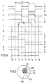
- Fig. 4 is a schematic diagram showing wave forms of the essential portion of the color sensor shown in Fig. 3,
- Fig. 5 is a front view showing a way of distributing the optical fibers of a light transferring path used in the embodiment shown in Fig. 3,
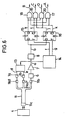
- Fig. 6 is a further example of the color sensor according to the present invention,
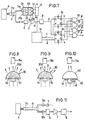
- Fig. 7 is a schematic diagram showing a still further example of the color sensor according to the present invention,
- Fig. 8 is a cross sectional view of an example of light emitting unit used in the color sensor according to the present invention,
- Figs. 9 and 10 are schematic diagram showing still further modification of the light emitting units used in the color sensor according to the present invention, and
- Fig. 11 is a schematic diagram showing an example of a color sensor having one colored light emitting source using a light transferring path with one end portion formed as shown in Fig. 5.
- Referring now to Fig. 3 there are provided two
light emitting sources light emitting sources divisional drive circuit 13 in a time divisional manner. Alight transmission path 11 is formed by a plurality of optical fibers bundled together with a part of the one end of bundled optical fibers of thelight transmission path 11 opposed adjacent to thelight emitting sources light entrance 11 a to which the light from thelight emitting sources photo receiving unit 6 to form alight exit 11 b to project the light reflected from theobject 4 on thephoto sensing unit 6. The other ends of the part of the optical fibers forming thelight entrance 11 a are disposed to face theobject 4 to form thelight exit 11c of light to project the light of thelight emitting sources object 4. The other ends of the remaining part of the optical fibers forming thelight exit 11 b for thephoto sensing unit 6 are disposed to face theobject 4 to form thelight entrance 11c for receiving the light reflected from theobject 4. At theend 11c of thelight transmission path 11, the respective optical fibers EX for receiving the light and the optical fibers PR for projecting the light are distributed alternately as shown in Fig. 5 to receive or project the light uniformly overall the area of theend 11c. - The
photo sensing unit 6 is formed by a single photo transistor to produce an analog signal corresponding to the quantity of the incident light to the photo transistor. - The
comparator 8 is applied with a reference voltage at one of the input terminals and compares the analog signal applied to another input terminal from theamplifier 7 with the reference voltage to provide an output of 1 or 0 depending on whether or not the analog signal exceeds the reference voltage. - Two flip-
flops comparator 8, i.e. the digital signal e to hold thereof at the timing when every strobe pulses f, g are applied. The flip-flops - AND
gates - Referring to Figs. 3 and 4, a
timing circuit 14 supplies timing signals to the timedivisional drive circuit 13, which produces drive current a and b to drive thelight emitting sources - By this arrangement both of the
light emitting sources object 4 in a time divisional manner passing through theentrance 11 a and thelight transmission path 11. It is to be noted that the periods during which thelight emitting source 1a emits the light are designated by t1 through t3, t5 through t, and the period during which thelight emitting source 1b emits the light is designated by t3 through t5. - The
object 4 illuminated reflects the light of a color corresponding to the color of the surface of the object and the reflected light passes theexit 11c and thelight transmission path 11 and is received by thephoto sensing unit 6, which is producing an analog signal of a large amplitude when the reflected light is received. As. shown in Fig. 4 assuming that theobject 4 having red color is illuminated from the timing t1, the amplitude of the analog signal of the output of thephoto sensing unit 6 becomes large in the time periods t1 through t3, t5 through t7 during which thelight emitting source 1a emits the light since theobject 4 reflects the red light and absorbs the green light, and the amplitude becomes small in the period t3 through t5 during which thelight emitting source 1b emits the light. - The analog signal from the
photo sensing unit 6 is amplified by theamplifier 7 to produce the analog signal d of the predetermined amplitude and is fed to thecomparator 8 to be compared with the reference voltage Vs. Thecomparator 8 produces the digital signals e, the level of which is 1 in the periods t, through t3 and t5 through t7 during which the amplitude of the analog signal is large and is 0 in the period t3 through t5 during which the amplitude of the analog signal is small. - The digital signals produced by the
comparator 8 are fed to the D input terminals of the flip-flops timing pulse generator 14. The D type flip-flop 15 holds the level of the digital signal e at the time of the positive edge of each of the strobe pulses f and the D type flip-flop 16 holds the level of the digital signal e at the positive edges of each of the strobe pulses g. By this operation, the output of the D type flip-flop 15 becomes 1 upon receipt of the strobe pulse f at the timing t2 in the periods of t, through t3 thereby the Q output thereof being 1 with the Q output being 0. The 1 level of the Q output of the flip-flop 15 shows theobject 4 has red color and the 1 level is held by the next positive edge of the strobe pulse f. - Since the digital signal e in the period t3 through t5 is 0, the Q output of the D type flip-
flop 16 becomes 0 upon receipt of the positive edge of the strobe pulse g at the timing t4 in the period t3 through t5 with the Q output of thereof being 1. The 0 level of the D type flip-flop 16 shows that thephoto sensing unit 6 does not receive the green light and the 0 level is held until the next strobe pulse g is applied. - The table 1 shows the relation of the output of flip-
flops photo sensing unit 6. - The AND
gates flops gate 18 receives the output signals h and k, the ANDgate 19 receives the output signals i and j, and the ANDgate 17 receives the output signals i and k. - Although the timings of the light emission by the
light emitting sources 1a a and 1b are shifted by To/2 each other, as the timings of the strobe pulses f and g are also shifted by To/2 and the state of the output of the D type flip-flop 15 can be held until the another flip-flop 16 reads in the output of thecomparator 8 upon receipt of the strobe pulse g, the ANDgates 17 through 20 receive the signals h, i, j, and k simultaneously. In Fig. 4, Y is the period for holding the output of thecomparator 8 and X is the period for judging the state of the output of the flip-flops. - The relationship between the color of the object and the states A, B, C and D of the outputs of the AND
gates gate 18 is 1 with the remaining outputs A, C and D being 0. In the table 2, the term "other color" means a color other than red, green, white and yellow. - According to the first embodiment of the color sensor according to the present invention, the four kinds of hues can be recognized or classified by using only two color light emitting sources and the recognition of the hue can be made in the real time basis. In this embodiment, the currents of the
light emitting diodes light emitting diodes object 4 and received by thephoto sensing unit 6 is lower than quantity of the reflected light of the object having red or green, eventually the output amplitude of theamplifier 7 for the yellow object is smaller than that for the red or green object. Thus, the reference voltage of thecomparator 8 is set to recognize the yellow by setting the reference voltage in such a manner that thecomparator 8 generates 1 in both cases when the red light is illuminated and when the green light is illuminated. - Since the red light and the green light are emitted in a time divisional manner, only one
comparator 8 is necessary for digitizing the analog signal fed from the amplifier or thephoto receiving unit 6, so that only one reference voltage can be used for the both of the red and green lights, thereby facilitating adjustment of the reference voltage without consideration about the balance of the reference voltage for each of colors. - It is not essential to use a light transmission path but the path can be separated two
paths 9 and 10 as shown in Fig. 2 one for illuminating the light on the object and another for receiving the reflected light from the object. - Fig. 6 shows the second embodiment of the color sensor according to the present invention wherein the
light entrance 11a of thelight transmission path 11 is divided into two light entrances 11a1 and 11a2 by dividing the bundled optical fibers two groups. Thelight entrance 11 a1 is disposed to face adjacently to the redlight emitting source 1 a and the light entrance 11a2 is disposed to face to thegreen light source 1b. - Fig. 7 shows the third embodiment of the color sensor according to the present invention wherein the
light entrance 11a of the color sensor shown in Fig. 3 is connected with alight emitting unit 20 having a box-like enclosure 21 made of an opaque material. Thelight emitting source face 21a of theenclosure 21 with the light emitting faces of thelight emitting sources opposite face 21 b on which thelight sntrance 11a of thelight transmission path 11 is connected. Theenclosure 21 is separated by alight diffuser 22 such as a sheet of frosted glass disposed between the both faces 21a and 21b. By this arrangement, the light emitted from thelight emitting source 1a and/or 1 b is diffused by thelight duffuser 22 and in turn the diffused light enters thelight entrance 11a. By using thelight diffuser 22, directionality of the light emitting sources such as light emitting diodes can be broadened so that the intensity of the light entering thelight entrance 11a from both of thelight emitting sources 1a a and 1 becomes uniform. The color recognition operation is similar to the arrangement shown in Fig. 3. - In order to broaden the directionality of the
light emitting diodes 1a a and 1b,hemispherical enclosure 30 may be used as shown in Fig. 8. In this embodiment, thelight emitting diodes enclosure 30 which is filled with a light diffusing material. Thelight entrance 11 a of thelight transmission path 11 is disposed to oppose the apex 30a of the hemispherical portion of theenclosure 30. - As the light emitting diodes,
GaAIAs diode 1a for the red light and GaAs:Si diode 1b for the infra red light may be used. For the light diffusing material, as shown in Fig. 9, anti-Stokes fluorescent material 31 may be filled in the enclosure uniformly, so that green light may be emitted by the infra red light emitted from thelight source 1 b. Although the shape of the enclosure is not limited to the hemispherical shape, in case of the hemispherical shape, quantity of the light entering the light transmission path may be increased. - Another modification of the light emitting unit is shown in Fig. 10, wherein a
layer 40 made of anti-Stokes fluorescent material is interposed between the GaAs:Si diode 41 and the flat face of ahemispherical enclosure 42 made of transparent material. - The GaAs:
Si diode 41, thelayer 40 and the flat face of theenclosure 42 may be adhered integrally. Theenclosure 42 acts as a lens to collimate both of the lights from thediodes light entrance 11a. - The bundled optical fibers with the end portions PR and EX thereof so uniformly distributed as shown in Fig. 5 may be used for the color sensor having one color
light emitting source 1 as shown in Fig. 11. - Although the embodiments of the color sensor described above are provided with two light emitting sources of different colors, the number of the colors of the light emitting source is not limited to two but n kinds of color light sources may be used to recognize 2" kinds of colored objects.


Claims (10)
Applications Claiming Priority (8)
| Application Number | Priority Date | Filing Date | Title |
|---|---|---|---|
| JP20376382A JPS5994022A (en) | 1982-11-22 | 1982-11-22 | Color sensor |
| JP203763/82 | 1982-11-22 | ||
| JP57203762A JPS5994021A (en) | 1982-11-22 | 1982-11-22 | Color sensor |
| JP203762/82 | 1982-11-22 | ||
| JP206856/82 | 1982-11-27 | ||
| JP57206856A JPS5997019A (en) | 1982-11-27 | 1982-11-27 | Color sensor |
| JP206857/82 | 1982-11-27 | ||
| JP57206857A JPS5997020A (en) | 1982-11-27 | 1982-11-27 | Color sensor |
Publications (3)
| Publication Number | Publication Date |
|---|---|
| EP0109686A2 EP0109686A2 (en) | 1984-05-30 |
| EP0109686A3 EP0109686A3 (en) | 1985-12-11 |
| EP0109686B1 true EP0109686B1 (en) | 1989-10-11 |
Family
ID=27476166
Family Applications (1)
| Application Number | Title | Priority Date | Filing Date |
|---|---|---|---|
| EP83111612A Expired EP0109686B1 (en) | 1982-11-22 | 1983-11-21 | Color sensor |
Country Status (3)
| Country | Link |
|---|---|
| US (1) | US4678338A (en) |
| EP (1) | EP0109686B1 (en) |
| DE (1) | DE3380707D1 (en) |
Families Citing this family (45)
| Publication number | Priority date | Publication date | Assignee | Title |
|---|---|---|---|---|
| FR2553309B1 (en) * | 1983-10-13 | 1988-11-10 | Blanc Philippe | METHOD FOR SORTING OBJECTS SUCH AS, IN PARTICULAR, FRUITS AND VEGETABLES, ACCORDING TO THEIR EXTERIOR APPEARANCE |
| GB2151018B (en) * | 1983-12-06 | 1987-07-22 | Gunsons Sortex Ltd | Sorting machine and method |
| US5158181A (en) * | 1985-10-29 | 1992-10-27 | Bailey Roger F | Optical sorter |
| EP0223446B1 (en) * | 1985-10-29 | 1991-03-27 | Roger Frederick Bailey | Optical sorting apparatus |
| JPH06105185B2 (en) * | 1986-05-16 | 1994-12-21 | ミノルタ株式会社 | Photoelectric conversion processor |
| DE3735176A1 (en) * | 1987-10-17 | 1989-04-27 | Draegerwerk Ag | DOSIMETER |
| ATE87737T1 (en) * | 1987-12-03 | 1993-04-15 | Siemens Ag | COLOR SENSOR ARRANGEMENT FOR DETECTING OBJECTS WITH COLORED SURFACES. |
| US4908676A (en) * | 1987-12-18 | 1990-03-13 | Bio-Recovery Systems, Inc. | Sensors for dissolved substances in fluids |
| US5077806A (en) * | 1989-06-01 | 1991-12-31 | Accuron Corporation | Machine vision analysis apparatus |
| US5073857A (en) * | 1989-06-01 | 1991-12-17 | Accuron Corporation | Method and apparatus for cell analysis |
| GB8913800D0 (en) * | 1989-06-15 | 1989-08-02 | Secr Defence | Colour monitoring |
| GB8918605D0 (en) * | 1989-08-15 | 1989-09-27 | Mckeown Samuel T J | Shade distinguishing device |
| US5117101A (en) * | 1990-08-13 | 1992-05-26 | Technostics Corporation | Tristimulus color recognition system with means for compensating for variations in light source color |
| US5229841A (en) * | 1991-07-10 | 1993-07-20 | Eaton Corporation | Color sensor employing optical fiber bundles with varied diameters |
| GB9213733D0 (en) * | 1992-06-29 | 1992-08-12 | Nycomed Pharma As | Light measurement apparatus |
| WO1994001755A1 (en) * | 1992-07-02 | 1994-01-20 | Michael Fredrick Feasey | Method and calibration device for calibrating computer monitors used in the printing and textile industries |
| JPH06208613A (en) * | 1992-11-13 | 1994-07-26 | Laurel Bank Mach Co Ltd | Pattern detector |
| US5407638A (en) * | 1993-04-28 | 1995-04-18 | Shell Oil Company | Detector-cell adapted for continuous-flow absorption detection |
| US5408326A (en) * | 1993-04-28 | 1995-04-18 | Shell Oil Company | Dual-wavelength absorption detector adapted for continuous-flow detection |
| DE4322865A1 (en) * | 1993-07-09 | 1995-01-12 | Bodenseewerk Geraetetech | Device for measuring the color of glass, especially broken glass |
| US5423554A (en) * | 1993-09-24 | 1995-06-13 | Metamedia Ventures, Inc. | Virtual reality game method and apparatus |
| IL108897A0 (en) * | 1994-03-08 | 1994-06-24 | Shimoni Yossi | Color meter |
| DE4420260C2 (en) * | 1994-06-10 | 1998-08-06 | Alfred Prof Dr Ing Leipertz | Method for determining color value components and color saturation |
| US5537211A (en) * | 1995-01-13 | 1996-07-16 | Triliance Corporation | Method and apparatus for selecting a wearable to match an object |
| US5642189A (en) * | 1995-06-12 | 1997-06-24 | Measurex Corporation | Color sensor simulating standard source illuminant |
| DE19617009C2 (en) * | 1996-04-27 | 1999-05-20 | Roland Man Druckmasch | Photoelectric measuring device |
| US5963333A (en) * | 1996-09-12 | 1999-10-05 | Color Savvy Systems Limited | Color sensor |
| DE19756515A1 (en) * | 1997-12-18 | 1999-06-24 | Bosch Siemens Hausgeraete | Washing machine for industrial or domestic use |
| ES2191920T3 (en) * | 1998-04-10 | 2003-09-16 | Datasensor Spa | PROCEDURE TO DISCRIMINATE THE COLOR OF A SURFACE AND APPLIANCE TO CARRY OUT THE PROCEDURE. |
| US5929999A (en) * | 1998-09-01 | 1999-07-27 | Hewlett-Packard Company | Light source for tristimulus colorimetry |
| US6008905A (en) * | 1998-12-22 | 1999-12-28 | Deus Ex Machina Inc. | Method and apparatus for determining the appearance of an object |
| US7050168B2 (en) | 1999-12-08 | 2006-05-23 | X-Rite, Incorporated | Optical measurement device and related process |
| US6369895B1 (en) | 2000-02-16 | 2002-04-09 | Electronics For Imaging, Inc. | Color measurement instrument with asymmetric tapered sample area optical enclosure |
| RU2207528C2 (en) * | 2000-11-13 | 2003-06-27 | Чернов Евгений Иванович | Procedure determining color of object and facility for its realization |
| DE10257640A1 (en) * | 2002-12-10 | 2004-07-08 | Siemens Ag | Device for recording the color impression of a surface |
| US7365854B2 (en) * | 2004-05-11 | 2008-04-29 | Nordson Corporation | Apparatus and methods for high speed RGB color discrimination |
| US7351245B2 (en) * | 2004-09-21 | 2008-04-01 | Bernice Joy Rozinsky | Apparatus and method for dislodging object from throat |
| US7996173B2 (en) | 2006-07-31 | 2011-08-09 | Visualant, Inc. | Method, apparatus, and article to facilitate distributed evaluation of objects using electromagnetic energy |
| US8076630B2 (en) | 2006-07-31 | 2011-12-13 | Visualant, Inc. | System and method of evaluating an object using electromagnetic energy |
| US8081304B2 (en) * | 2006-07-31 | 2011-12-20 | Visualant, Inc. | Method, apparatus, and article to facilitate evaluation of objects using electromagnetic energy |
| EP2110355A1 (en) * | 2008-04-19 | 2009-10-21 | Fife-Tidland GmbH | Device for optical recording of the lateral location of features on moving material sheets and method for operating this device |
| US8888207B2 (en) | 2012-02-10 | 2014-11-18 | Visualant, Inc. | Systems, methods and articles related to machine-readable indicia and symbols |
| US9316581B2 (en) | 2013-02-04 | 2016-04-19 | Visualant, Inc. | Method, apparatus, and article to facilitate evaluation of substances using electromagnetic energy |
| US9041920B2 (en) | 2013-02-21 | 2015-05-26 | Visualant, Inc. | Device for evaluation of fluids using electromagnetic energy |
| WO2014165003A1 (en) | 2013-03-12 | 2014-10-09 | Visualant, Inc. | Systems and methods for fluid analysis using electromagnetic energy |
Family Cites Families (25)
| Publication number | Priority date | Publication date | Assignee | Title |
|---|---|---|---|---|
| US3351409A (en) * | 1963-06-12 | 1967-11-07 | Irvin H Mcguire | Light diffusion material, method of making and using same |
| US3449053A (en) * | 1965-04-29 | 1969-06-10 | Mc Donnell Douglas Corp | Microscopic examining apparatus utilizing scanning techniques |
| FR1589461A (en) * | 1968-09-18 | 1970-03-31 | ||
| US3709615A (en) * | 1969-02-28 | 1973-01-09 | Calumet Photographic Inc | Integrating light meter with movable meter mechanism |
| US3593055A (en) * | 1969-04-16 | 1971-07-13 | Bell Telephone Labor Inc | Electro-luminescent device |
| US3609044A (en) * | 1969-07-01 | 1971-09-28 | Eastman Kodak Co | Apparatus for selectively inspecting a web surface and a coating on the surface |
| DE2116386A1 (en) * | 1971-03-30 | 1972-10-12 | Wenzel, Martin, Prof.Dr., 1000 Berlin | Arrangement for measuring the light absorption |
| US3725701A (en) * | 1971-10-26 | 1973-04-03 | Andros Inc | Fluorescent source non-dispersive infrared gas analyzer |
| GB1410823A (en) * | 1972-10-06 | 1975-10-22 | Inst Fuer Grafische Technik | Method and a device for rapidly sensing and providing signals characteristic of colour tones of opaque or transparent material |
| US3942185A (en) * | 1972-12-13 | 1976-03-02 | U.S. Philips Corporation | Polychromatic electroluminescent device |
| US3910701A (en) * | 1973-07-30 | 1975-10-07 | George R Henderson | Method and apparatus for measuring light reflectance absorption and or transmission |
| JPS50141382A (en) * | 1974-02-22 | 1975-11-13 | ||
| US3986777A (en) * | 1974-08-22 | 1976-10-19 | Weber Dental Mfg. Co., Div. Of Sterndent Corporation | Tristimulus colorimeter for use in the fabrication of artificial teeth |
| US3994590A (en) * | 1975-04-29 | 1976-11-30 | Martini Raymond G Di | Discrete frequency colorimeter |
| CA1050795A (en) * | 1975-12-23 | 1979-03-20 | Byron E. Marcus | Diffusion device for compensating for non-uniform photomultiplier cathode sensitivity |
| DE2726606A1 (en) * | 1977-06-13 | 1978-12-21 | Max Planck Gesellschaft | MEDICAL SPECTRAL PHOTOMETER |
| US4149228A (en) * | 1977-07-22 | 1979-04-10 | The United States Of America As Represented By The Secretary Of The Army | Compact uniform light diffuser and attenuator |
| JPS609708Y2 (en) * | 1978-03-23 | 1985-04-05 | 蓊 須賀 | Integrating sphere standard light source device |
| SE418997B (en) * | 1978-06-26 | 1981-07-06 | Asea Ab | FIBEROPTICAL TEMPERATURE SENSOR BASED ON THE MEASUREMENT OF THE TEMPERATURE-DEPENDENT SPECTRAL ABSORPTION FORM OF A MATERIAL |
| JPS5616826A (en) * | 1979-07-20 | 1981-02-18 | Matsushita Electric Ind Co Ltd | Color detector |
| JPS5712352A (en) * | 1980-06-26 | 1982-01-22 | Hajime Sangyo Kk | Light diffusion device |
| DE3024773A1 (en) * | 1980-06-30 | 1982-01-28 | Grapho-Metronic Meß- und Regeltechnik GmbH & Co, KG, 8000 München | METHOD AND DEVICE FOR CONTROLLING AND CONTROLLING THE COLORING OF A MULTICOLOR PRINTING MACHINE |
| DE3038786A1 (en) * | 1980-10-14 | 1982-04-29 | Fraunhofer-Gesellschaft zur Förderung der angewandten Forschung e.V., 8000 München | METHOD FOR MEASURING THE COLOR OF THE GUM |
| US4476982A (en) * | 1981-04-01 | 1984-10-16 | Sunkist Growers, Inc. | Method and apparatus for grading articles according to their surface color |
| DD203632A1 (en) * | 1981-09-09 | 1983-10-26 | Univ Berlin Humboldt | FAST METHOD AND DEVICE FOR PHOTOMETRIC BLOOD TESTING |
-
1983
- 1983-11-21 DE DE8383111612T patent/DE3380707D1/en not_active Expired
- 1983-11-21 EP EP83111612A patent/EP0109686B1/en not_active Expired
- 1983-11-22 US US06/554,363 patent/US4678338A/en not_active Expired - Lifetime
Also Published As
| Publication number | Publication date |
|---|---|
| EP0109686A2 (en) | 1984-05-30 |
| DE3380707D1 (en) | 1989-11-16 |
| US4678338A (en) | 1987-07-07 |
| EP0109686A3 (en) | 1985-12-11 |
Similar Documents
| Publication | Publication Date | Title |
|---|---|---|
| US4678338A (en) | Color sensor | |
| US4127773A (en) | Characterizing and identifying materials | |
| US4076979A (en) | Bottle color identification apparatus | |
| US4818847A (en) | Apparatus for optically reading printed information | |
| EP0537431B1 (en) | Device for the optical recognition of documents | |
| EP0324000B1 (en) | Document illuminating apparatus | |
| US3662181A (en) | Scanning apparatus for the detection and identification of luminescing code bars on articles | |
| US6784996B2 (en) | Color sorting apparatus for granular object with optical detection device consisting of CCD linear sensor | |
| US3890221A (en) | Translucency/opaque sorting | |
| US6885393B2 (en) | Illuminating unit for an article-sensing camera | |
| US4329591A (en) | Method for detecting samples | |
| CN101238359A (en) | Device and method for collecting and detecting light emitted by a lighting device | |
| JPH11156310A (en) | Article classifying method and apparatus | |
| RU2005123809A (en) | OPTICAL RECOGNITION DEVICE FOR DETECTING OPTICAL SIGNS OF SECURITIES | |
| US3880289A (en) | Sorting field corn from sweet corn | |
| US4074292A (en) | System for indicating photographic information | |
| EP0284347A2 (en) | A device for inspecting the degree of vacuum in a sealed vessel | |
| JPH0378568B2 (en) | ||
| CN216817478U (en) | Paper money detection device based on two optical phenomena and paper money counter | |
| JPS5960327A (en) | Color measuring device | |
| US4177449A (en) | Photoelectric converter apparatus | |
| CN217543902U (en) | Paper money detection device of currency count machine | |
| CN2177954Y (en) | The detector receives the intermediate device of different colored light sources | |
| GB1568366A (en) | Apparatus and method for characterising and/or identifying materials using luminescence | |
| JPS5994021A (en) | Color sensor |
Legal Events
| Date | Code | Title | Description |
|---|---|---|---|
| PUAI | Public reference made under article 153(3) epc to a published international application that has entered the european phase |
Free format text: ORIGINAL CODE: 0009012 |
|
| AK | Designated contracting states |
Designated state(s): DE GB IT |
|
| PUAL | Search report despatched |
Free format text: ORIGINAL CODE: 0009013 |
|
| AK | Designated contracting states |
Designated state(s): DE GB IT |
|
| 17P | Request for examination filed |
Effective date: 19860531 |
|
| 17Q | First examination report despatched |
Effective date: 19871019 |
|
| GRAA | (expected) grant |
Free format text: ORIGINAL CODE: 0009210 |
|
| ITF | It: translation for a ep patent filed | ||
| AK | Designated contracting states |
Kind code of ref document: B1 Designated state(s): DE GB IT |
|
| REF | Corresponds to: |
Ref document number: 3380707 Country of ref document: DE Date of ref document: 19891116 |
|
| PLBE | No opposition filed within time limit |
Free format text: ORIGINAL CODE: 0009261 |
|
| STAA | Information on the status of an ep patent application or granted ep patent |
Free format text: STATUS: NO OPPOSITION FILED WITHIN TIME LIMIT |
|
| 26N | No opposition filed | ||
| ITTA | It: last paid annual fee | ||
| REG | Reference to a national code |
Ref country code: GB Ref legal event code: IF02 |
|
| PGFP | Annual fee paid to national office [announced via postgrant information from national office to epo] |
Ref country code: GB Payment date: 20021120 Year of fee payment: 20 |
|
| PGFP | Annual fee paid to national office [announced via postgrant information from national office to epo] |
Ref country code: DE Payment date: 20021121 Year of fee payment: 20 |
|
| PG25 | Lapsed in a contracting state [announced via postgrant information from national office to epo] |
Ref country code: GB Free format text: LAPSE BECAUSE OF EXPIRATION OF PROTECTION Effective date: 20031120 |
|
| REG | Reference to a national code |
Ref country code: GB Ref legal event code: PE20 |