EP0109484A2 - Warngerät für Hubschrauber - Google Patents
Warngerät für Hubschrauber Download PDFInfo
- Publication number
- EP0109484A2 EP0109484A2 EP83107382A EP83107382A EP0109484A2 EP 0109484 A2 EP0109484 A2 EP 0109484A2 EP 83107382 A EP83107382 A EP 83107382A EP 83107382 A EP83107382 A EP 83107382A EP 0109484 A2 EP0109484 A2 EP 0109484A2
- Authority
- EP
- European Patent Office
- Prior art keywords
- height
- warning
- helicopter
- tail
- tail rotor
- Prior art date
- Legal status (The legal status is an assumption and is not a legal conclusion. Google has not performed a legal analysis and makes no representation as to the accuracy of the status listed.)
- Ceased
Links
Images

Classifications
-
- B—PERFORMING OPERATIONS; TRANSPORTING
- B64—AIRCRAFT; AVIATION; COSMONAUTICS
- B64C—AEROPLANES; HELICOPTERS
- B64C27/00—Rotorcraft; Rotors peculiar thereto
- B64C27/006—Safety devices
Definitions
- the present invention relates to a warning device, for a helicopter with a tail rotor, which emits a warning signal when the tail is in such a position as to be in danger of making contact with the ground or an obstruction.
- the tail rotor can contact the ground even though all helicopters with a tail rotor have a mechanical protection device.
- This device may consist simply of an arm or bar structure which extends from the tail from in front of the rotor downwardly and then rearwardly to a level below the level of the arc described by the tips of the blade. In other cases it is formed by a bar on a tail fin.
- the specific extent and the direction of the axis of the mechanical device is approved for each helicopter by the official flight worthiness certifying authority of a country and is specifically for protection in the flare situation. However, if, as is natural, the pilot has sought the softest ground, e.g. a ploughed field, the mechanical protection arm or device for the tail rotors may enter the soft ground without the pilot being aware of it and then the tail rotor will contact.
- the softest ground e.g. a ploughed field
- the device comprises, in addition to a device determining the flying altitude of the helicopter, a device responding to the attitude of the helicopter, and a computer receiving the output signals from both devices, which computes the proximity of the helicopter tail to the ground from the flying altitude, the rate of vertical descent and the attitude, and emits a warning signal when a certain threshold value is reached.
- This known device assumes that the two devices determining the flying altitude and attitude are both necessary and are operating absolutely exactly, i.e. expensive measuring instruments, namely a precision altimeter and a precision vertical gyro, must be built into the helicopter.
- the devices are mounted at the front of the helicopter and they would have to be calibrated and set up very accurately to allow for the long tail since, as mentioned,small changes of inclination make a large difference in the height of the tail rotor. For this reason, the device is also intended essentially for first fitting-outs of large helicopters. Subsequently fitting existing smaller and simple helicopters, particularly those for practice purposes, is almost impossible for economic reasons. It is also considered that the device could not be clearly successful in practice because of its complexity. To the best of the applicant's knowledge, a practical arrangement in accordance with this proposal has not been put on the market - at least in Europe.
- the present invention arises from the realization that all the previously proposed devices are too complicated or inadequate because they are positioned in the wrong place.
- the height-finder has been positioned at the front. In this position, pointing forwards and downwards it protects the craft by giving the pilot warning of an obstruction ahead of the helicopter which is being approached too low for safety. If the tail is to be protected with such an arrangement an attitude indicator, with its added expense and complexity is necessary as proposed in German OLS 25 49 884.
- the inventor realized that the warning device height-finding element should be positioned near the tail and if this is done, the need for attitude measurements can be avoided, the weight and complexity of the warning arrangement can be minimised, and the device made to function more effectively.
- the direction of the beam is preferably substantially along or adjacent and parallel to the axis of the tail rotor mechanical protection device.
- the warning device according to the invention emits warning signals when the tail of the helicopter comes "too close” to the ground, the warning distance not being a constant, but depending on the rate of vertical descent of the helicopter.
- the microprocessor or computing means of the warning device is, therefore, programmed,for each helicopter type, so that the distances from the ground at which the warning signals are released are greater, the greater the rate of vertical descent of the helicopter.
- the warning device therefore, gives the pilot an aid, which enables him to carry out auto-rotation without any danger of tail impact.
- Useful training in auto-rotation landing is, therefore, made possible even in the absence of an instructor.
- the device can be contained in a housing-with- - releasable clamps for clamping the housing to the tail and in this case the device preferably includes an aircraft frequency transmitter for transmitting the warning signal to the helicopter radio receiver and an independent power supply. It can, of course, be enough for a helicopter flying school to have one or two such warning devices, which are then mounted on the helicopters with which it is desired to practise an auto-rotation landing.
- the "add-on" device version should have its own current supply and, therefore, operate completely independently. It is also important that the arrangement, particularly when using radar beams, can be kept very small and weighs only a small amount, approximately 1 kg.
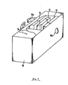
- the "add-on" device is housed in a protective housing 10 which has securing clamps lOa on one of its sides.
- a radar height-finder unit 11 There are accommodated in the housing a radar height-finder unit 11, a computer or microprocessor unit 12, a radio transmitter unit 13 and an electrical battery power supply 14.
- lOb denotes an aperture in the protective housing 10, through which the height-finder 11 emits a radar beam.
- the signal output of the height-finder 11 is connected to the computer 12 whose output then controls the radio transmitter 13.
- the current supply for the devices 11, 12 and 13 is provided by the battery power supply 14.
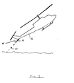
- Figure 2 shows diagrammatically the warning device of Figure 1 mounted on the mechanical protection device 15 of the tail 16 of a helicopter with a tail rotor.
- this mechanical device consists of an arm or bar structure extending downwardly, from in front of the tail rotor, to extend under the lower arc traced by the tips of the tail rotor blades.
- the device is mounted so that the axis of the radar beam is substantially in line with or parallel with the axis of the bar.
- FIG.3 A block diagram circuit arrangement of the warning device of Figures 1 and 2 is shown in Fig.3.
- diagram parts corresponding to the parts illustrated in Figures 1 and 2 have been given the same references.
- the housing 10 is indicated by a dot/dash line with the opening lOb at its lower end and the units 11 to 14 are surrounded by dashed lines. Through the opening lOb the radar beam 17 is transmitted and received from the ground 18.
- the battery power supply 14 comprises a battery or accumulator 19 and a power supply arrangement 20 which converts the battery output into appropriate voltages for the other circuit elements of the warning device.
- Battery charging and battery test signal sockets 21 are provided on the housing 10.
- Outputs from the power supply 20 are connected for battery testing to an interface unit 22 which forms part of the microprocessor device 12. Power is supplied for operation by means not shown from supply 14 to the units 11, 12 and 13.
- the radar height-finding arrangement comprises a timing oscillator and divider unit 23 which has outputs coupled to the interface unit 22, a gate circuit 43 and a filter and modulation amplifier 24.
- the output of the filter and modulation amplifier unit is coupled to an X-band height-finder radar module 25.
- module can be used, one suitable example being that made by Plessey Ltd. under the type number GDSM2.
- the radar signal output of the module 25 forms, through the antenna 26, the radar height-finding beam 17 and the height output of the module 25 is coupled via a filter and pre-amplifier/limiter unit 27 to a gate 43.
- the output from gate unit 43 is fed via the interface unit 22 to a microprocessor calculator 28.
- the microprocessor unit 12 comprises in addition to the calculator unit 28 a store 29, for storing calculation constants and which is coupled to the calculator 28.
- An output of calculator 28 is coupled to a warning tone generator 30 which is also fed by a warning signal store 31, the parts 30 and 31 also forming part of the overall microprocessor unit 12.
- the VHF radio transmitter unit 13 comprises a standard flight VHF radio transmitter 32, for example a King transmitter and this unit 32 has a quarz controlled transmitter oscillator unit 33.
- the output of the radio transmitter 13 is coupled to a transmitting antenna lOc.
- Fig.3 Also shown in Fig.3 is part of the helicopter instrumentation referenced 34. This comprises the normal radio receiving antenna 35 coupled to the standard flight radio receiver 36 the output of which is coupled to a loudspeaker or head-phones unit 37.
- the housing 10 has a servicing or test socket 38 by which signals can be checked for the units via the interface 22.
- the radar height-finding or altimeter unit 11 - operates in normal manner.
- the radar module 25 is supplied with a continuous wave modulation signal by means of the timing oscillator and divider unit 23 and the filter and modulation amplifier 24.
- the modulated radar signal is beamed to the ground and the return signal is processed in module 25 to derive the instantaneous height of the helicopter tail above the surface of the ground or other obstruction in the path of the beam 17.
- the processed signals are fed to the filter and pre-amplifier unit 27 and the amplified height representative output signals of unit 27 are fed to the gate 43.
- Gate 43 is opened periodically by sampling signals from the timing oscillator 23 and the height signals are passed by the opened gate to the microprocessor calculator 28 via the interface 22.
- the microprocessor calculator 28 calculates, using timing signals received from the unit 23 and the sampled height signals from the height-finder 11, the sink rate of the helicopter tail portion.
- the sink rate and the instantaneous height are compared with calculation constants from the store 29 and, if the height falls below a predetermined limit for the relevant sink rate, a warning signal is generated and fed to the warning tone generator 30.
- the warning tone generator 30 transmits a warning in accordance with the warning signals stored in the store 31 to the radio transmitter 32 which transmits it via the transmission antenna lOc. This transmitted warning signal is received over the normal VHF radio receiver 36 from the antenna 35 and a warning will be heard by the pilot either over the loudspeaker or the head-phones 37.
- the rate of sampling of the height signal by gate 43 and timing oscillator 23 may be lower at higher altitudes than at low altitudes and arrangements not shown may be provided to vary the sampling rate dependent upon the instantaneous height measurement.
- the stores 31 and 29 may be made exchangeable so as to provide respectively for different types of warnings and also to provide for different calculation constants appropriate to different types of helicopters.
- the transmission oscillator 33 may be changeable to provide for the different receiving frequencies of the receiver of the different helicopters to which the unit may be fitted. If the transmitter 32 is a broad band transmitter, this will avoid the need for many otherwise necessary changes of the transmission "oscillator". This will not unduly interfere with other air traffic since it is intended that the transmission range should be small, e.g. not exceeding the 50m range, and only sufficient to be reliably picked up by the helicopter receiver.
- the device shown can, of course, be changed in many ways. This concerns particularly the shape of the housing 10, which is advantageously of an aerodynamic design.
- the height-finder 11 can also, for example, operate with laser beams or other electromagnetic wave radiation, but for reasons of size and weight a radar height-finder indicator is to be preferred.
- the microprocessor unit 12 can also be replaced by another electronic computer. It is advantageous if the microprocessor 12 is suitable for storing several fixed programmes, because it is then particularly simple to use the same device both for the auto-rotation landing and for other flying manoeuvres in different helicopters.
- a warning device can be fitted as permanent equipment in the original construction of a helicopter.
- the equipment since the equipment may be so small, most of it may be mounted at the tail in this original fitting version also.
- the transmitter 13 would not be needed and the warning signal could be brought to the pilot in any more convenient way.
Landscapes
- Engineering & Computer Science (AREA)
- Mechanical Engineering (AREA)
- Aviation & Aerospace Engineering (AREA)
- Radar Systems Or Details Thereof (AREA)
Applications Claiming Priority (2)
| Application Number | Priority Date | Filing Date | Title |
|---|---|---|---|
| DE19823228557 DE3228557A1 (de) | 1982-07-30 | 1982-07-30 | Warnvorrichtung fuer hubschrauber |
| DE3228557 | 1982-07-30 |
Publications (2)
| Publication Number | Publication Date |
|---|---|
| EP0109484A2 true EP0109484A2 (de) | 1984-05-30 |
| EP0109484A3 EP0109484A3 (de) | 1984-08-15 |
Family
ID=6169756
Family Applications (1)
| Application Number | Title | Priority Date | Filing Date |
|---|---|---|---|
| EP83107382A Ceased EP0109484A3 (de) | 1982-07-30 | 1983-07-27 | Warngerät für Hubschrauber |
Country Status (3)
| Country | Link |
|---|---|
| US (1) | US4528564A (de) |
| EP (1) | EP0109484A3 (de) |
| DE (1) | DE3228557A1 (de) |
Cited By (3)
| Publication number | Priority date | Publication date | Assignee | Title |
|---|---|---|---|---|
| EP0139283A1 (de) * | 1983-10-17 | 1985-05-02 | Ulrich Trampnau | Landunghilfe |
| US5827819A (en) * | 1990-11-01 | 1998-10-27 | Oregon Health Sciences University | Covalent polar lipid conjugates with neurologically active compounds for targeting |
| US6063759A (en) * | 1990-11-01 | 2000-05-16 | Oregon Health Sciences University | Conjugate of biologically active compound and polar lipid conjugated to a microparticle for biological targeting |
Families Citing this family (24)
| Publication number | Priority date | Publication date | Assignee | Title |
|---|---|---|---|---|
| US4769645A (en) * | 1983-06-10 | 1988-09-06 | Sundstrand Data Control, Inc. | Excessive pitch attitude warning system for rotary wing aircraft |
| DE3434758C2 (de) * | 1984-09-21 | 1986-08-07 | Ulrich 8000 München Trampnau | Landehilfe für Hubschrauber |
| US4916445A (en) * | 1988-11-09 | 1990-04-10 | Crossley Simon M | Obstruction proximity indication system for an aircraft |
| US6043759A (en) * | 1996-07-29 | 2000-03-28 | Alliedsignal | Air-ground logic system and method for rotary wing aircraft |
| US5781126A (en) * | 1996-07-29 | 1998-07-14 | Alliedsignal Inc. | Ground proximity warning system and methods for rotary wing aircraft |
| DE19822017A1 (de) * | 1998-05-15 | 1999-12-16 | Deep Blue Technology Ag Lenzbu | Vorrichtung zur Erzeugung eines Warnsignals, insbesondere für Helikopter |
| US6234422B1 (en) * | 1998-12-01 | 2001-05-22 | Alexander A. Bolonkin | Uniblade air rotor and flight and covercraft vehicles with its |
| DE19930559B4 (de) * | 1999-07-02 | 2004-08-12 | Airbus Deutschland Gmbh | Anordnung und Verfahren zum Schutz eines Flugzeugrumpfes |
| US6422517B1 (en) * | 1999-12-02 | 2002-07-23 | Boeing Company | Aircraft tailstrike avoidance system |
| MXPA04003285A (es) * | 2001-10-10 | 2004-07-23 | Mcloughlin Pacific Corp | Metodo y aparato para rastrear aeronaves y para seguridad contra el accesp no autorizado. |
| US6995689B2 (en) * | 2001-10-10 | 2006-02-07 | Crank Kelly C | Method and apparatus for tracking aircraft and securing against unauthorized access |
| US6845944B2 (en) * | 2003-04-11 | 2005-01-25 | The Boeing Company | Multi-positional tail skids and associated methods of use |
| US7126496B2 (en) * | 2004-09-30 | 2006-10-24 | Safe Flight Instrument Corporation | Tactile cueing system and method for aiding a helicopter pilot in making landings |
| US7274309B2 (en) * | 2005-03-29 | 2007-09-25 | Nance C Kirk | Aircraft landing gear initial touch-down velocity monitor |
| US7274310B1 (en) | 2005-03-29 | 2007-09-25 | Nance C Kirk | Aircraft landing gear kinetic energy monitor |
| US7751976B2 (en) * | 2005-08-26 | 2010-07-06 | Sikorsky Aircraft Corporation | Rotary wing aircraft flight control system with a proximity cueing and avoidance system |
| US8032269B2 (en) * | 2007-05-18 | 2011-10-04 | Sikorsky Aircraft Corporation | Control surface failure detection for fly-by-wire aircraft |
| US8042765B1 (en) | 2008-05-20 | 2011-10-25 | Nance C Kirk | Aircraft landing gear compression rate monitor |
| US8264377B2 (en) | 2009-03-02 | 2012-09-11 | Griffith Gregory M | Aircraft collision avoidance system |
| US9196168B2 (en) * | 2009-05-20 | 2015-11-24 | Textron Innovations Inc. | Collision avoidance and warning system |
| WO2013179150A1 (en) | 2012-05-30 | 2013-12-05 | Aselsan Elektronik Sanayi Ve Ticaret Anonim Sirketi | A detection mechanism |
| USD705407S1 (en) * | 2012-12-20 | 2014-05-20 | David O. Edmonds | Ceiling fan |
| US9284047B2 (en) * | 2013-08-02 | 2016-03-15 | Goodrich Corporation | Routings for articulated landing gear |
| US11682313B2 (en) | 2021-03-17 | 2023-06-20 | Gregory M. Griffith | Sensor assembly for use in association with aircraft collision avoidance system and method of using the same |
Family Cites Families (9)
| Publication number | Priority date | Publication date | Assignee | Title |
|---|---|---|---|---|
| DE1124824B (de) * | 1957-05-31 | 1962-03-01 | Christian Tilenius Dipl Ing | Vorrichtung zur Hindernisanzeige fuer langsam fliegende und landende Flugzeuge |
| US3250121A (en) * | 1964-01-31 | 1966-05-10 | Conductron Corp | Helicopter ground proximity indicator |
| FR1605307A (de) * | 1964-06-23 | 1974-08-02 | ||
| US3947808A (en) * | 1975-01-13 | 1976-03-30 | Sundstrand Data Control, Inc. | Excessive descent rate warning system for aircraft |
| GB1537263A (en) * | 1975-01-30 | 1978-12-29 | Plessey Co Ltd | Aircraft ground-proximity warning systems |
| DE2511233C2 (de) * | 1975-03-14 | 1977-03-10 | Dornier Gmbh | Verfahren zur Verhinderung ungewollter Land- oder Wasserberührung von in niedriger Höhe fliegenden Fluggeräten |
| US4027838A (en) * | 1975-03-18 | 1977-06-07 | United Technologies Corporation | Helicopter warning system |
| IL48315A (en) * | 1975-03-18 | 1978-08-31 | United Technologies Corp | Warning system for helicopters for avoiding tail contact during landing |
| IL57402A (en) * | 1978-09-20 | 1982-05-31 | Israel Aircraft Ind Ltd | Excessive descent-rate warning system |
-
1982
- 1982-07-30 DE DE19823228557 patent/DE3228557A1/de not_active Withdrawn
-
1983
- 1983-07-27 EP EP83107382A patent/EP0109484A3/de not_active Ceased
- 1983-07-28 US US06/517,941 patent/US4528564A/en not_active Expired - Fee Related
Cited By (8)
| Publication number | Priority date | Publication date | Assignee | Title |
|---|---|---|---|---|
| EP0139283A1 (de) * | 1983-10-17 | 1985-05-02 | Ulrich Trampnau | Landunghilfe |
| US5827819A (en) * | 1990-11-01 | 1998-10-27 | Oregon Health Sciences University | Covalent polar lipid conjugates with neurologically active compounds for targeting |
| US6024977A (en) * | 1990-11-01 | 2000-02-15 | Oregon Health Sciences University | Covalent polar lipid conjugates with neurologically active compounds for targeting |
| US6063759A (en) * | 1990-11-01 | 2000-05-16 | Oregon Health Sciences University | Conjugate of biologically active compound and polar lipid conjugated to a microparticle for biological targeting |
| US6339060B1 (en) | 1990-11-01 | 2002-01-15 | Oregon Health & Science University | Conjugate of biologically active compound and polar lipid conjugated to a microparticle for biological targeting |
| US6436437B1 (en) | 1990-11-01 | 2002-08-20 | Oregon Health And Science University | Covalent polar lipid conjugates with neurologically active compounds for targeting |
| US6858582B2 (en) | 1990-11-01 | 2005-02-22 | Oregon Health And Sciences University | Composition containing porous microparticle impregnated with biologically-active compound for treatment of infection |
| US7423010B2 (en) | 1994-05-19 | 2008-09-09 | Oregon Health & Science University | Nonporous microparticle-prodrug conjugates for treatment of infection |
Also Published As
| Publication number | Publication date |
|---|---|
| US4528564A (en) | 1985-07-09 |
| EP0109484A3 (de) | 1984-08-15 |
| DE3228557A1 (de) | 1984-02-09 |
Similar Documents
| Publication | Publication Date | Title |
|---|---|---|
| US4528564A (en) | Warning device for helicopters | |
| EP0139283B1 (de) | Landunghilfe | |
| US6005513A (en) | Portable flight guidance and tracking system | |
| US5186418A (en) | Self guided recoverable airborne instrument module | |
| US6144899A (en) | Recoverable airborne instrument platform | |
| WO1992015078A1 (en) | Helicopter remote control system | |
| US5614907A (en) | All weather visual system for helicopters | |
| US4769645A (en) | Excessive pitch attitude warning system for rotary wing aircraft | |
| US3739385A (en) | Mechanically swept radar antenna for use with an aircraft landing monitor system | |
| US3546350A (en) | Training method and apparatus for ils landings | |
| KR100923167B1 (ko) | 전자파 간섭원의 공간위치 모니터링 장치 및 그 방법 | |
| US3423051A (en) | Homing system for aircraft | |
| US3623093A (en) | Radar installation | |
| US20190061917A1 (en) | Information transmission system, information transmission method, and aircraft | |
| GB2106223A (en) | An arrangement for target control of a bomb dropped from an aircraft | |
| Pagels et al. | Helicopter assisted landing system-millimeter-wave against brown-out | |
| DE3434758A1 (de) | Landehilfe fuer hubschrauber | |
| RU1777300C (ru) | Способ посадки планирующей парашютной системы на наземный радиомаяк | |
| JPH0584279B2 (de) | ||
| BIEHL et al. | Flight test investigation of the wake vortices generated by helicopters | |
| SCHUETTE et al. | Unmanned helicopters for battlefield and maritime surveillance | |
| PURSEL et al. | A flight investigation of system accuracies and operation capabilities of an air transport area navigation system[Final Report, Sep. 1974- Apr. 1975] | |
| Kirner | Independent Landing Monitor | |
| RU94013030A (ru) | Устройство для измерения высоты морских волн с летательного аппарата | |
| Bothe | Instigation and processing of flight tests in DLR |
Legal Events
| Date | Code | Title | Description |
|---|---|---|---|
| PUAI | Public reference made under article 153(3) epc to a published international application that has entered the european phase |
Free format text: ORIGINAL CODE: 0009012 |
|
| AK | Designated contracting states |
Designated state(s): CH DE FR GB IT LI |
|
| PUAL | Search report despatched |
Free format text: ORIGINAL CODE: 0009013 |
|
| AK | Designated contracting states |
Designated state(s): CH DE FR GB IT LI |
|
| 17P | Request for examination filed |
Effective date: 19850211 |
|
| 17Q | First examination report despatched |
Effective date: 19860214 |
|
| STAA | Information on the status of an ep patent application or granted ep patent |
Free format text: STATUS: THE APPLICATION HAS BEEN REFUSED |
|
| 18R | Application refused |
Effective date: 19870507 |