EP0109263A1 - Rohrverschlüsse, z.B. Tankverschlusskappen für Fahrzeuge - Google Patents
Rohrverschlüsse, z.B. Tankverschlusskappen für Fahrzeuge Download PDFInfo
- Publication number
- EP0109263A1 EP0109263A1 EP83306845A EP83306845A EP0109263A1 EP 0109263 A1 EP0109263 A1 EP 0109263A1 EP 83306845 A EP83306845 A EP 83306845A EP 83306845 A EP83306845 A EP 83306845A EP 0109263 A1 EP0109263 A1 EP 0109263A1
- Authority
- EP
- European Patent Office
- Prior art keywords
- members
- closure
- pipe end
- spigot
- flange
- Prior art date
- Legal status (The legal status is an assumption and is not a legal conclusion. Google has not performed a legal analysis and makes no representation as to the accuracy of the status listed.)
- Ceased
Links
Images

Classifications
-
- B—PERFORMING OPERATIONS; TRANSPORTING
- B60—VEHICLES IN GENERAL
- B60K—ARRANGEMENT OR MOUNTING OF PROPULSION UNITS OR OF TRANSMISSIONS IN VEHICLES; ARRANGEMENT OR MOUNTING OF PLURAL DIVERSE PRIME-MOVERS IN VEHICLES; AUXILIARY DRIVES FOR VEHICLES; INSTRUMENTATION OR DASHBOARDS FOR VEHICLES; ARRANGEMENTS IN CONNECTION WITH COOLING, AIR INTAKE, GAS EXHAUST OR FUEL SUPPLY OF PROPULSION UNITS IN VEHICLES
- B60K15/00—Arrangement in connection with fuel supply of combustion engines or other fuel consuming energy converters, e.g. fuel cells; Mounting or construction of fuel tanks
- B60K15/03—Fuel tanks
- B60K15/04—Tank inlets
- B60K15/0406—Filler caps for fuel tanks
- B60K15/0409—Provided with a lock
Definitions
- This invention relates to closures for flanged pipe ends.
- a known such closure for example a vehicle fuel filler cap, comprises a seal to engage the pipe end, a member to extend into the pipe end, and a pair of projections extending radially outwardly from the member.
- the projections are passed through a pair of cut-aways in the flanged end and then the closure is twisted so that the projections move behind the flange.
- the flange has a cam surface adjacent each cut-away against which the respective projection bears with more force as the closure is twisted to pull the seal against the pipe end.
- a closure for a flanged pipe end with at least two cut-aways in the flange including two members which are relatively rotatable and are movable towards and away from each other along the axis of rotation, means to bias the members towards each other, means to force the members apart against the biasing means upon rotation of the members from a first relative position, and means to hold the members in a second position of relative rotation, one of the members being provided with sealing means engageable with the pipe end and having means to register said one member with the pipe end, and the other member having at least two projections arranged so that upon offering up the closure to the pipe end with the members in said second relative position the two projections can pass through the two cut-aways and the registering means engages the pipe end, and so that upon subsequent rotation of said other member the projections move behind the flange and the members move towards each other under the action of the biasing means as the members approach said first relative position so that the projections engage and are urged against the flange and the
- An advantage of the closure according to the invention is that it may be fitted to the pipe end more easily than the known closure because the projections forcefully engage the flange only towards the end of the locking movement from the second relative position to the first relative position, and the biasing means is at that stage assisting the locking movement. Furthermore, the closure may be removed more easily, because during removal the locking projections are initially forced away from the flange. Additionally, the closure according to the invention does not require camming surfaces adjacent the pipe flange cut-aways in order to provide a good seal.
- a cap for a motor vehicle fuel filler pipe 11, shown in Figure 4, is indicated generally by the reference numeral 10 in Figures 1 and 2.
- the cap 10 comprises a domed plastics knob 12 from which extends a drive spigot 14 which may be integral with the knob 12 or a separate moulding welded thereto.
- the spigot 14 carries an annular intermediate member 16 of plastics which is free to rotate within limits on the spigot 14.
- the spigot 14 and intermediate member 16 are provided with complementary thrust faces engaging at 18 and further features which house an O-ring 20 to provide a seal between the spigot and intermediate member.
- the intermediate member 16 carries an annular gasket 22 abutting a shoulder 24 of the intermediate member and arranged to seal against the end 26 of the pipe 11.
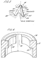
- the pipe end which is also a plastics moulding, has an inturned flange 28 and a pair of opposed cut-outs 30 are formed in the flange.
- the intermediate member 16 has a pair of opposed radially outwardly directed keys 32 arranged to engage the cut-outs 30 in the pipe flange 28.
- the spigot 14 also carries a annular locking member 34 which can slide along the spigot 14 but is prevented from rotation relative to the spigot.
- the locking member has a pair of opposed axially extending slots 36 which are engaged by a metal pin 38 extending transversely through and secured to the spigot 14.
- a spring-loaded over-centre action is provided between the locking member 34 and the intermediate member 16.
- Three metal pins 40 with rounded ends are equally spaced around the spigot. Each pin 40 has one end engaging a respective socket 42 in the intermediate member 16 and the other end engaging a respective socket 44 in the locking member 34.
- a helical coil compression spring 46 is disposed in an annular cavity formed between the spigot 14 and the locking member 34. One end of the spring 46 bears on the transverse pin 38 and the other end bears against a shoulder formed on the locking member, and the spring 46 acts, inter alia, to hold the pins 40 in engagement with the sockets 42, 44.
- Suitable stops are provided between the intermediate member 16 and the knob 12 or spigot 14 or locking member 34, so that the intermediate member can be rotated between two positions relative to the locking member 34, in one of which positions all of the pins 40 are inclined one way around the spigot 14 and in the other position are all inclined the other way around the spigot 14.
- the over-centre action of the pins 40 causes the locking member 34 to move axially away from and then return towards the intermediate member 16.
- a pair of opposed radially outwardly directed locking projections 48 are provided on the locking member 34.
- each locking projection 48 is aligned with a respective one of the keys 32 and the cap 10 can be fitted to the pipe 11, the locking projections 48 passing through the flange cut-outs 30 and the keys 32 engaging in the cut-outs 30.
- the upper surfaces 49 of the locking projections 48 are at a level slightly below the lower surface 50 of the pipe flange 28.
- the over-centre action is arranged so that the pins 40 are further over centre in the locked position than in the unlocked position and thus the spacing between the intermediate member 16 and the locking member is less in the locked position than in the unlocked position.
- the locking member 34 rotates, but the intermediate member is prevented from rotation by the keys 32 engaging the flange cut-outs 30 and so that over-centre action operates.
- the projections 48 rotate and move axially towards and into engagement with the flange.
- the cap and pipe are arranged so that the action of the spring 46 causes the gasket 22 to be compressed to form a good seal as the over-centre action reaches its stop in the locked position.
- the cap is easy to fit to and remove from the pipe, particularly because during fitting of the cap the locking projections 48 forcefully engage the pipe flange 28 only towards the end of the locking movement, when the spring 46 is assisting the locking movement, and during removal of the cap the projections 48 are initially urged away from the flange 28 by the action of the pins 40.
- the cap may be modified.
- the locking member 34 may be formed as two parts, one being fixed to the spigot 14 and the other being slidable on the spigot with a sliding dog connection to the first part.
- only one of the keys 32 on the intermediate member 16 need be provided to register the intermediate member 16 with the pipe end 11.
- a key operated lock assembly may be utilised to prevent unauthorised removal of the cap 10 from the pipe 11.
Landscapes
- Engineering & Computer Science (AREA)
- Life Sciences & Earth Sciences (AREA)
- Sustainable Development (AREA)
- Sustainable Energy (AREA)
- Chemical & Material Sciences (AREA)
- Combustion & Propulsion (AREA)
- Transportation (AREA)
- Mechanical Engineering (AREA)
- Cooling, Air Intake And Gas Exhaust, And Fuel Tank Arrangements In Propulsion Units (AREA)
- Quick-Acting Or Multi-Walled Pipe Joints (AREA)
Applications Claiming Priority (2)
| Application Number | Priority Date | Filing Date | Title |
|---|---|---|---|
| GB8231968 | 1982-11-09 | ||
| GB08231968A GB2129783A (en) | 1982-11-09 | 1982-11-09 | Pipe closures for example vehicle fuel filler caps |
Publications (1)
| Publication Number | Publication Date |
|---|---|
| EP0109263A1 true EP0109263A1 (de) | 1984-05-23 |
Family
ID=10534138
Family Applications (1)
| Application Number | Title | Priority Date | Filing Date |
|---|---|---|---|
| EP83306845A Ceased EP0109263A1 (de) | 1982-11-09 | 1983-11-09 | Rohrverschlüsse, z.B. Tankverschlusskappen für Fahrzeuge |
Country Status (3)
| Country | Link |
|---|---|
| EP (1) | EP0109263A1 (de) |
| ES (1) | ES275593Y (de) |
| GB (1) | GB2129783A (de) |
Cited By (1)
| Publication number | Priority date | Publication date | Assignee | Title |
|---|---|---|---|---|
| FR2704211A1 (fr) * | 1993-04-22 | 1994-10-28 | Journee Paul Sa | Bouchon amovible pour l'obturation de l'extrémité d'une tubulure de remplissage d'un réservoir de combustible gazeux. |
Families Citing this family (4)
| Publication number | Priority date | Publication date | Assignee | Title |
|---|---|---|---|---|
| GB2169591B (en) * | 1985-01-11 | 1988-07-13 | Bothwell P W | Method of opening and closing a tank and filler structure for use in the method |
| US6209745B1 (en) * | 1999-06-04 | 2001-04-03 | Jansson And Associates Masterbuilders, Inc. | Pop up flush-mount gas cap |
| GB201610527D0 (en) | 2016-06-16 | 2016-08-03 | Ostomycure As | Lid |
| USD818590S1 (en) | 2016-06-16 | 2018-05-22 | Ostomycure As | Lid for a medical implant |
Citations (3)
| Publication number | Priority date | Publication date | Assignee | Title |
|---|---|---|---|---|
| DE2312125A1 (de) * | 1973-03-10 | 1974-09-12 | Ymos Metallwerke Wolf & Becker | Tankverschlusskappe |
| GB2070577A (en) * | 1980-02-14 | 1981-09-09 | Daimler Benz Ag | Tank closure cap |
| EP0080624A1 (de) * | 1981-11-26 | 1983-06-08 | Reutter Metallwarenfabrik GmbH | Verschlussdeckel, insbesondere für einen Kraftstofftank |
Family Cites Families (4)
| Publication number | Priority date | Publication date | Assignee | Title |
|---|---|---|---|---|
| GB798739A (en) * | 1957-01-16 | 1958-07-23 | Chester Charles Depew | Improvements in or relating to tank filler caps |
| DE1586601A1 (de) * | 1967-01-03 | 1970-06-25 | Martin Espinal | Registrierende Pillenabgabevorrichtung |
| GB1250172A (de) * | 1968-09-24 | 1971-10-20 | ||
| CH528416A (de) * | 1970-08-13 | 1972-09-30 | Dubach Werner | Verschluss für Behälter, insbesondere Krüge, Flaschen und Kannen |
-
1982
- 1982-11-09 GB GB08231968A patent/GB2129783A/en not_active Withdrawn
-
1983
- 1983-11-08 ES ES1983275593U patent/ES275593Y/es not_active Expired
- 1983-11-09 EP EP83306845A patent/EP0109263A1/de not_active Ceased
Patent Citations (3)
| Publication number | Priority date | Publication date | Assignee | Title |
|---|---|---|---|---|
| DE2312125A1 (de) * | 1973-03-10 | 1974-09-12 | Ymos Metallwerke Wolf & Becker | Tankverschlusskappe |
| GB2070577A (en) * | 1980-02-14 | 1981-09-09 | Daimler Benz Ag | Tank closure cap |
| EP0080624A1 (de) * | 1981-11-26 | 1983-06-08 | Reutter Metallwarenfabrik GmbH | Verschlussdeckel, insbesondere für einen Kraftstofftank |
Cited By (1)
| Publication number | Priority date | Publication date | Assignee | Title |
|---|---|---|---|---|
| FR2704211A1 (fr) * | 1993-04-22 | 1994-10-28 | Journee Paul Sa | Bouchon amovible pour l'obturation de l'extrémité d'une tubulure de remplissage d'un réservoir de combustible gazeux. |
Also Published As
| Publication number | Publication date |
|---|---|
| ES275593Y (es) | 1984-12-16 |
| GB2129783A (en) | 1984-05-23 |
| ES275593U (es) | 1984-05-16 |
Similar Documents
| Publication | Publication Date | Title |
|---|---|---|
| US4000633A (en) | Locking gas cap with torque override feature | |
| US4132091A (en) | Self locking fuel cap | |
| US7448236B2 (en) | Coupler latch lock and method of use | |
| US4222253A (en) | Steering lock for motor vehicles | |
| US4342208A (en) | Locking gas cap with torque override feature | |
| US3477607A (en) | Lockable spout closure cap | |
| US3901407A (en) | Locking cap assembly for a filler neck | |
| US4231240A (en) | Screw plug assembly | |
| US4142388A (en) | Tumbler wheels for combination locks | |
| US20080223095A1 (en) | Locking System With Hidden Keyed Access | |
| US4035921A (en) | Lockable spout closure assembly | |
| EP2327581B1 (de) | Verschliessbare kappe für einen brennstofftank | |
| US4453388A (en) | Locking fuel cap | |
| EP0189265B1 (de) | Verriegelbare Betätigungsvorrichtung | |
| EP0109263A1 (de) | Rohrverschlüsse, z.B. Tankverschlusskappen für Fahrzeuge | |
| US6935527B1 (en) | Locking filler cap | |
| US4160511A (en) | Device for capping supplying opening of fuel-tank | |
| US4376492A (en) | Closure member for the fuel tank of an automotive vehicle | |
| US3125363A (en) | Vehicle locking hub | |
| US4377243A (en) | Lock for fuel tank cover | |
| US1786332A (en) | Tank-closure lock | |
| US5125249A (en) | Lock for gear shift lever | |
| EP0014794A1 (de) | Drehklinke und Verfahren zur Bedienung | |
| GB2068346A (en) | Caps for vehicle filler pipes | |
| GB1581095A (en) | Lock with two key-receiving members |
Legal Events
| Date | Code | Title | Description |
|---|---|---|---|
| PUAI | Public reference made under article 153(3) epc to a published international application that has entered the european phase |
Free format text: ORIGINAL CODE: 0009012 |
|
| AK | Designated contracting states |
Designated state(s): DE FR IT |
|
| 17P | Request for examination filed |
Effective date: 19840712 |
|
| STAA | Information on the status of an ep patent application or granted ep patent |
Free format text: STATUS: THE APPLICATION HAS BEEN REFUSED |
|
| 18R | Application refused |
Effective date: 19860316 |
|
| RIN1 | Information on inventor provided before grant (corrected) |
Inventor name: EVANS, RICHARD JOHN REES |