EP0109112B1 - Adjustable turning-mechanism for shutters - Google Patents
Adjustable turning-mechanism for shutters Download PDFInfo
- Publication number
- EP0109112B1 EP0109112B1 EP83201515A EP83201515A EP0109112B1 EP 0109112 B1 EP0109112 B1 EP 0109112B1 EP 83201515 A EP83201515 A EP 83201515A EP 83201515 A EP83201515 A EP 83201515A EP 0109112 B1 EP0109112 B1 EP 0109112B1
- Authority
- EP
- European Patent Office
- Prior art keywords
- turning
- shaft
- axle
- case
- shutter
- Prior art date
- Legal status (The legal status is an assumption and is not a legal conclusion. Google has not performed a legal analysis and makes no representation as to the accuracy of the status listed.)
- Expired
Links
- 230000005540 biological transmission Effects 0.000 abstract 1
- 238000009434 installation Methods 0.000 abstract 1
- 239000000463 material Substances 0.000 description 2
- 229920003023 plastic Polymers 0.000 description 2
- 239000004033 plastic Substances 0.000 description 2
- 239000002184 metal Substances 0.000 description 1
Images

Classifications
-
- E—FIXED CONSTRUCTIONS
- E05—LOCKS; KEYS; WINDOW OR DOOR FITTINGS; SAFES
- E05F—DEVICES FOR MOVING WINGS INTO OPEN OR CLOSED POSITION; CHECKS FOR WINGS; WING FITTINGS NOT OTHERWISE PROVIDED FOR, CONCERNED WITH THE FUNCTIONING OF THE WING
- E05F11/00—Man-operated mechanisms for operating wings, including those which also operate the fastening
- E05F11/36—Man-operated mechanisms for operating wings, including those which also operate the fastening specially designed for passing through a wall
-
- E—FIXED CONSTRUCTIONS
- E05—LOCKS; KEYS; WINDOW OR DOOR FITTINGS; SAFES
- E05Y—INDEXING SCHEME ASSOCIATED WITH SUBCLASSES E05D AND E05F, RELATING TO CONSTRUCTION ELEMENTS, ELECTRIC CONTROL, POWER SUPPLY, POWER SIGNAL OR TRANSMISSION, USER INTERFACES, MOUNTING OR COUPLING, DETAILS, ACCESSORIES, AUXILIARY OPERATIONS NOT OTHERWISE PROVIDED FOR, APPLICATION THEREOF
- E05Y2900/00—Application of doors, windows, wings or fittings thereof
- E05Y2900/10—Application of doors, windows, wings or fittings thereof for buildings or parts thereof
- E05Y2900/13—Type of wing
- E05Y2900/146—Shutters
Definitions
- the invention relates to a device to open and close a shutter from the inside of a house, which shutter is hinged at the outside of the house and which device comprises a driving shaft, and turning-axle and a housing in which the worm-gear is placed, which gear consists of a worm and a wheel of which the worm is fixed on the driving shaft and the wheel of the worm-gear on the turning axle and that on the turning axle is mounted a hinge-blade which blade can be connected to the shutter, for example by means of screws, and that the device is fixed to the wall of the house such that the housing can move horizontally in the longitudinal direction of the driving-shaft over a short range.
- Such a device is known for a long time and described in the Swiss patent CH 103 600.
- a disadvantage of this known device is that the hinge-blade when it is fixed to the device, can not be moved up and down along the turning axle; it can only move over a certain distance in the direction of the driving-shaft and it could eventually turn around the axis of the driving-shaft. This means, that when the hinges of the shutter have worn out, or due to other reasons the shutter has moved down, forces will act on the device, now, that the shutter takes up another position.
- the hinge-blade is fixed in one possible position relative to the axis of the worm-gear.
- the object of the invention is a device which can be used to open over at least 180 degrees a shutter from the inside of a house and to put the shutter in any desired fixed position and that the connection of the device with as well as the hinge-blade as with the house is such, that the hinge-blade can take any desired position with respect to the device, that is to say, that it can move over a short distance up and down along the axle and in a direction perpendicular to the axle.
- the hinge-blade has a single boss which can be placed on one end of the turning axle, such that it can move along the axle over a certain distance and that the boss is connected to the axle by means of for example splines so that it cannot turn about the axle but is free to move up and down over a certain distance along the axle. If such a device according to the invention is fixed to a house and a shutter, the hinge-blade when fixed to the shutter and connected to the device can move up and down the axle and together with the device in the longitudinal direction of the turning-shaft, that is to say the hinge-blade can move freely within a short distance in any direction.
- the housing is mounted inside a guiding-case in which the housing can be fixed in a desired position by means of an adjusting bolt and a tapped hole and which guiding-case can be fixed to the wall, for example by means of screws, and that the guiding-case is open at one side, through which opening the turning-shaft protrudes.
- This embodiment of the device acccording to the invention can be used not only to open and close a shutter but also as one of the hinges of the shutter, because the device is fixed to the wall of the house.
- the driving-shaft has a squared end on which can be placed a service handle of hand crank lever at the inside of the house.
- Figures 1 and 2 show a turning-mechanism which consists of a case 1 in which in the usual way a turning-axle with a wheel 2 and a driving-shaft with a worm 3 are borne.
- the end of the turning-axle 2 is provided with edge-shaped splines 2a, on which a hinge-blade also with wedge-shaped splines (see figure 4) is mounted.
- the end of the driving-shaft 3 has been squared 3a. On the squared end can be mounted on operating lever 13 (see in figure 5).
- In the case 1 is made a tapped hole 4 for an adjusting-bolt 6 as shown in figure 3.
- Figure 3 shows a guiding-case 5 with a mounting-sheet 5a which can be made of metal or another material and in which guiding-case is an open slot-hole 5b and a round hole 5c, which are placed such, that the turning-axle 2 and the driving-shaft 3 of the turning-mechainsm can slide without hindrance.
- an adjusting bolt 6 which is mounted together with the mounting sheet 5a on a window-fram 7, the case 1 inside the guiding-case 5 can be adjusted.
- the length of the guiding-case should be of sufficient length.
- the empty space which is left at the inside of the guiding-case 5 after the case had been adjusted, should be shortened in such a way, that the outside of the guiding-case 5 should not come in touch with the inside of the turning- circle of the shutter (figure 6).
- the open end of the guiding-case 5 can be covered by a lid 9, made of plastics for instance.
- FIG 4 shows a so-called "third hinge-blade” 10 which shape is similar to the usual shape of most hinges, with the exception of the boss 11, which is provided with a hole with wedge-shaped splines, which can be slid on to the splined end 2a of the turning-shaft 2.
- the shape of the "third hinge-blade” could be changed either by means of a bend 12 or by using an adjustable hinge-joint, which hinge-joint could be fixable in such a way that the boss 11, after the assembled mechanism is mounted on the window-frame, will lay above the ending of the turning-shaft 2 and so that the "third hinge-blade" lies closely against the shutter.
- Figure 5 shows one of the possible shapes of the hand crank lever 13, with which the turning-mechanism can be put into operation.
- Figure 6 shows the device according to the invention mounted on a window-frame 14 with a shutter 15 which in the drawing is shown inside the window-frame; figure 6 also shows how the turning-mechanism operates.
- the driving shaft 3 is borne at the inside of the house in the window-frame 14 by means of a bearing 16, made out of plastics material, which secures the proper operation of the turning-mechanism.
Landscapes
- Operating, Guiding And Securing Of Roll- Type Closing Members (AREA)
- Hinges (AREA)
- Air-Flow Control Members (AREA)
- Helmets And Other Head Coverings (AREA)
- Particle Accelerators (AREA)
- Shutters For Cameras (AREA)
Abstract
Description
- The invention relates to a device to open and close a shutter from the inside of a house, which shutter is hinged at the outside of the house and which device comprises a driving shaft, and turning-axle and a housing in which the worm-gear is placed, which gear consists of a worm and a wheel of which the worm is fixed on the driving shaft and the wheel of the worm-gear on the turning axle and that on the turning axle is mounted a hinge-blade which blade can be connected to the shutter, for example by means of screws, and that the device is fixed to the wall of the house such that the housing can move horizontally in the longitudinal direction of the driving-shaft over a short range.
- Such a device is known for a long time and described in the Swiss patent CH 103 600. A disadvantage of this known device is that the hinge-blade when it is fixed to the device, can not be moved up and down along the turning axle; it can only move over a certain distance in the direction of the driving-shaft and it could eventually turn around the axis of the driving-shaft. This means, that when the hinges of the shutter have worn out, or due to other reasons the shutter has moved down, forces will act on the device, now, that the shutter takes up another position. In general the hinge-blade is fixed in one possible position relative to the axis of the worm-gear.
- The object of the invention is a device which can be used to open over at least 180 degrees a shutter from the inside of a house and to put the shutter in any desired fixed position and that the connection of the device with as well as the hinge-blade as with the house is such, that the hinge-blade can take any desired position with respect to the device, that is to say, that it can move over a short distance up and down along the axle and in a direction perpendicular to the axle.
- This aim is achieved with a device according to the invention in that the hinge-blade has a single boss which can be placed on one end of the turning axle, such that it can move along the axle over a certain distance and that the boss is connected to the axle by means of for example splines so that it cannot turn about the axle but is free to move up and down over a certain distance along the axle. If such a device according to the invention is fixed to a house and a shutter, the hinge-blade when fixed to the shutter and connected to the device can move up and down the axle and together with the device in the longitudinal direction of the turning-shaft, that is to say the hinge-blade can move freely within a short distance in any direction.
- In another possible embodiment of the device according to the invention the housing is mounted inside a guiding-case in which the housing can be fixed in a desired position by means of an adjusting bolt and a tapped hole and which guiding-case can be fixed to the wall, for example by means of screws, and that the guiding-case is open at one side, through which opening the turning-shaft protrudes. This embodiment of the device acccording to the invention can be used not only to open and close a shutter but also as one of the hinges of the shutter, because the device is fixed to the wall of the house. Preferably the driving-shaft has a squared end on which can be placed a service handle of hand crank lever at the inside of the house.
- The invention will be explained more in detail by means of the drawing in which one of the possible embodiments of the device according to the invention is represented. In the drawing show:
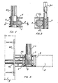
- Fig. 1 a front-view of a worm-gear inside a case according to the invention;
- Fig. 2 a cross-section according to line II-II of figure 1;
- Fig. 3 in a cross-section a guiding-case together with a case according to line III-III of figure 2;
- Fig. 4 a hinge-blade in front and top-view;
- Fig. 5 a hand crank lever or service handle;
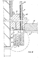
- Fig. 6 a device according to the invention mounted on a window-frame and shutter.
- Figures 1 and 2 show a turning-mechanism which consists of a case 1 in which in the usual way a turning-axle with a
wheel 2 and a driving-shaft with aworm 3 are borne. The end of the turning-axle 2 is provided with edge-shaped splines 2a, on which a hinge-blade also with wedge-shaped splines (see figure 4) is mounted. The end of the driving-shaft 3 has been squared 3a. On the squared end can be mounted on operating lever 13 (see in figure 5). In the case 1 is made a tapped hole 4 for an adjusting-bolt 6 as shown in figure 3. - Figure 3 shows a guiding-
case 5 with a mounting-sheet 5a which can be made of metal or another material and in which guiding-case is an open slot-hole 5b and a round hole 5c, which are placed such, that the turning-axle 2 and the driving-shaft 3 of the turning-mechainsm can slide without hindrance. By means of an adjustingbolt 6 which is mounted together with the mounting sheet 5a on a window-fram 7, the case 1 inside the guiding-case 5 can be adjusted. - It should be noticed that due to extreme variations in dimensions, particularly of existing old shutters, the length of the guiding-case should be of sufficient length. The empty space which is left at the inside of the guiding-
case 5 after the case had been adjusted, should be shortened in such a way, that the outside of the guiding-case 5 should not come in touch with the inside of the turning- circle of the shutter (figure 6). After cutting off the peice 8 of the guiding-case 15, the open end of the guiding-case 5 can be covered by a lid 9, made of plastics for instance. - Figure 4 shows a so-called "third hinge-blade" 10 which shape is similar to the usual shape of most hinges, with the exception of the
boss 11, which is provided with a hole with wedge-shaped splines, which can be slid on to thesplined end 2a of the turning-shaft 2. The shape of the "third hinge-blade" could be changed either by means of abend 12 or by using an adjustable hinge-joint, which hinge-joint could be fixable in such a way that theboss 11, after the assembled mechanism is mounted on the window-frame, will lay above the ending of the turning-shaft 2 and so that the "third hinge-blade" lies closely against the shutter. - Figure 5 shows one of the possible shapes of the
hand crank lever 13, with which the turning-mechanism can be put into operation. - Figure 6 shows the device according to the invention mounted on a window-
frame 14 with a shutter 15 which in the drawing is shown inside the window-frame; figure 6 also shows how the turning-mechanism operates. - The driving
shaft 3 is borne at the inside of the house in the window-frame 14 by means of abearing 16, made out of plastics material, which secures the proper operation of the turning-mechanism.
Claims (3)
Priority Applications (1)
| Application Number | Priority Date | Filing Date | Title |
|---|---|---|---|
| AT83201515T ATE39533T1 (en) | 1982-11-08 | 1983-10-21 | ADJUSTABLE TURNING DEVICE FOR SHUTTERS. |
Applications Claiming Priority (2)
| Application Number | Priority Date | Filing Date | Title |
|---|---|---|---|
| NL8204325A NL8204325A (en) | 1982-11-08 | 1982-11-08 | ADJUSTABLE ROTATION MECHANICS FOR EXISTING AND NEW HATCHES OR SIMILAR HORIZONTALLY MOVABLE CLOSING DEVICES. |
| NL8204325 | 1982-11-08 |
Publications (2)
| Publication Number | Publication Date |
|---|---|
| EP0109112A1 EP0109112A1 (en) | 1984-05-23 |
| EP0109112B1 true EP0109112B1 (en) | 1988-12-28 |
Family
ID=19840549
Family Applications (1)
| Application Number | Title | Priority Date | Filing Date |
|---|---|---|---|
| EP83201515A Expired EP0109112B1 (en) | 1982-11-08 | 1983-10-21 | Adjustable turning-mechanism for shutters |
Country Status (4)
| Country | Link |
|---|---|
| EP (1) | EP0109112B1 (en) |
| AT (1) | ATE39533T1 (en) |
| DE (1) | DE3378777D1 (en) |
| NL (1) | NL8204325A (en) |
Family Cites Families (4)
| Publication number | Priority date | Publication date | Assignee | Title |
|---|---|---|---|---|
| DE489159C (en) * | 1930-01-14 | Heinrich Ellermann | Laterally adjustable fishing clamps for shutters, gates and the like. like | |
| CH103600A (en) * | 1922-11-08 | 1924-02-16 | Emile Rimey Octave Eugene | Device for operating shutters and shutters from inside apartments. |
| DE2125626A1 (en) * | 1971-05-24 | 1972-12-07 | Taylor, Lloyd S , Naples, Fla (V St A) | Adjustable pivot bearing for doors |
| FR2504969A1 (en) * | 1981-04-30 | 1982-11-05 | Geissert Eugene | Casement window shutter operation from indoors - involves spur rod engaging wing spindle teeth, with bracket mounted eccentric lever |
-
1982
- 1982-11-08 NL NL8204325A patent/NL8204325A/en unknown
-
1983
- 1983-10-21 EP EP83201515A patent/EP0109112B1/en not_active Expired
- 1983-10-21 AT AT83201515T patent/ATE39533T1/en not_active IP Right Cessation
- 1983-10-21 DE DE8383201515T patent/DE3378777D1/en not_active Expired
Also Published As
| Publication number | Publication date |
|---|---|
| NL8204325A (en) | 1984-06-01 |
| DE3378777D1 (en) | 1989-02-02 |
| EP0109112A1 (en) | 1984-05-23 |
| ATE39533T1 (en) | 1989-01-15 |
Similar Documents
| Publication | Publication Date | Title |
|---|---|---|
| US5036899A (en) | Panel garage door opening and closing | |
| CA1139326A (en) | Operator for a casement-type window | |
| HUP0001653A2 (en) | Revolving door drive mechanism with an electronic controlling means | |
| US5701636A (en) | Adjustable door hinge | |
| EP0777028B1 (en) | An operator with at least two linkage mechanisms for opening and closing pivotal windows | |
| CA2136332A1 (en) | Compact counterbalancing system for sectional doors | |
| US5102174A (en) | Gearing for espagnolette fitting | |
| GB2119435A (en) | Cupboard with a double door | |
| US4286411A (en) | Manual balanced door with door closer arm | |
| ES2562683T3 (en) | Home appliance | |
| AU730907B2 (en) | Drive device for a stop barrier | |
| EP0109112B1 (en) | Adjustable turning-mechanism for shutters | |
| US4143556A (en) | Motorized vent operator | |
| EP0629762B1 (en) | Compact window operator | |
| GB2236555A (en) | Pivoting door: control arm and slide track | |
| CA2125722A1 (en) | Compact window operator | |
| US4100647A (en) | Pivot device for doors of strong boxes, safes or the like | |
| GR3003329T3 (en) | Gearing for winding-up and unwinding a roller shutter consisting of several lamellas as well as shell belonging to it | |
| EP0094943B1 (en) | Gear operated remote control mirror | |
| EP0179180B1 (en) | Bevel gear | |
| ATE110816T1 (en) | ACTUATION GEAR FOR WINDOW AND DOOR LOCKS O. DGL. | |
| WO2003042479A1 (en) | Casement window operator system | |
| CA2079682C (en) | Fitting with a worm drive for moving a hinged window or door leaf | |
| CA1142562A (en) | Latch having a releasable actuating rod | |
| WO1984004349A1 (en) | Device at window shutters |
Legal Events
| Date | Code | Title | Description |
|---|---|---|---|
| PUAI | Public reference made under article 153(3) epc to a published international application that has entered the european phase |
Free format text: ORIGINAL CODE: 0009012 |
|
| AK | Designated contracting states |
Designated state(s): AT BE CH DE FR GB IT LI LU NL SE |
|
| 17P | Request for examination filed |
Effective date: 19841127 |
|
| R17P | Request for examination filed (corrected) |
Effective date: 19850123 |
|
| 17Q | First examination report despatched |
Effective date: 19861001 |
|
| D17Q | First examination report despatched (deleted) | ||
| GRAA | (expected) grant |
Free format text: ORIGINAL CODE: 0009210 |
|
| AK | Designated contracting states |
Kind code of ref document: B1 Designated state(s): AT BE CH DE FR GB IT LI LU NL SE |
|
| PG25 | Lapsed in a contracting state [announced via postgrant information from national office to epo] |
Ref country code: SE Effective date: 19881228 Ref country code: LI Effective date: 19881228 Ref country code: IT Free format text: LAPSE BECAUSE OF FAILURE TO SUBMIT A TRANSLATION OF THE DESCRIPTION OR TO PAY THE FEE WITHIN THE PRESCRIBED TIME-LIMIT;WARNING: LAPSES OF ITALIAN PATENTS WITH EFFECTIVE DATE BEFORE 2007 MAY HAVE OCCURRED AT ANY TIME BEFORE 2007. THE CORRECT EFFECTIVE DATE MAY BE DIFFERENT FROM THE ONE RECORDED. Effective date: 19881228 Ref country code: FR Free format text: THE PATENT HAS BEEN ANNULLED BY A DECISION OF A NATIONAL AUTHORITY Effective date: 19881228 Ref country code: CH Effective date: 19881228 Ref country code: AT Effective date: 19881228 |
|
| REF | Corresponds to: |
Ref document number: 39533 Country of ref document: AT Date of ref document: 19890115 Kind code of ref document: T |
|
| REF | Corresponds to: |
Ref document number: 3378777 Country of ref document: DE Date of ref document: 19890202 |
|
| REG | Reference to a national code |
Ref country code: CH Ref legal event code: PL |
|
| EN | Fr: translation not filed | ||
| PG25 | Lapsed in a contracting state [announced via postgrant information from national office to epo] |
Ref country code: GB Effective date: 19891021 |
|
| PG25 | Lapsed in a contracting state [announced via postgrant information from national office to epo] |
Ref country code: LU Free format text: LAPSE BECAUSE OF NON-PAYMENT OF DUE FEES Effective date: 19891031 |
|
| PLBE | No opposition filed within time limit |
Free format text: ORIGINAL CODE: 0009261 |
|
| STAA | Information on the status of an ep patent application or granted ep patent |
Free format text: STATUS: NO OPPOSITION FILED WITHIN TIME LIMIT |
|
| 26N | No opposition filed | ||
| GBPC | Gb: european patent ceased through non-payment of renewal fee | ||
| PG25 | Lapsed in a contracting state [announced via postgrant information from national office to epo] |
Ref country code: DE Effective date: 19900703 |
|
| PGFP | Annual fee paid to national office [announced via postgrant information from national office to epo] |
Ref country code: NL Payment date: 19911031 Year of fee payment: 9 |
|
| PGFP | Annual fee paid to national office [announced via postgrant information from national office to epo] |
Ref country code: BE Payment date: 19911211 Year of fee payment: 9 |
|
| PG25 | Lapsed in a contracting state [announced via postgrant information from national office to epo] |
Ref country code: BE Effective date: 19921031 |
|
| BERE | Be: lapsed |
Owner name: DE JONG REIJER Effective date: 19921031 |
|
| PG25 | Lapsed in a contracting state [announced via postgrant information from national office to epo] |
Ref country code: NL Effective date: 19930501 |
|
| NLV4 | Nl: lapsed or anulled due to non-payment of the annual fee |