EP0108960A2 - Flüssigkeitslager für axial bewegbaren Kopf - Google Patents
Flüssigkeitslager für axial bewegbaren Kopf Download PDFInfo
- Publication number
- EP0108960A2 EP0108960A2 EP83110483A EP83110483A EP0108960A2 EP 0108960 A2 EP0108960 A2 EP 0108960A2 EP 83110483 A EP83110483 A EP 83110483A EP 83110483 A EP83110483 A EP 83110483A EP 0108960 A2 EP0108960 A2 EP 0108960A2
- Authority
- EP
- European Patent Office
- Prior art keywords
- lens assembly
- housing
- annular chamber
- biasing force
- storage medium
- Prior art date
- Legal status (The legal status is an assumption and is not a legal conclusion. Google has not performed a legal analysis and makes no representation as to the accuracy of the status listed.)
- Granted
Links
Images

Classifications
-
- G—PHYSICS
- G11—INFORMATION STORAGE
- G11B—INFORMATION STORAGE BASED ON RELATIVE MOVEMENT BETWEEN RECORD CARRIER AND TRANSDUCER
- G11B7/00—Recording or reproducing by optical means, e.g. recording using a thermal beam of optical radiation by modifying optical properties or the physical structure, reproducing using an optical beam at lower power by sensing optical properties; Record carriers therefor
- G11B7/08—Disposition or mounting of heads or light sources relatively to record carriers
- G11B7/085—Disposition or mounting of heads or light sources relatively to record carriers with provision for moving the light beam into, or out of, its operative position or across tracks, otherwise than during the transducing operation, e.g. for adjustment or preliminary positioning or track change or selection
-
- G—PHYSICS
- G11—INFORMATION STORAGE
- G11B—INFORMATION STORAGE BASED ON RELATIVE MOVEMENT BETWEEN RECORD CARRIER AND TRANSDUCER
- G11B7/00—Recording or reproducing by optical means, e.g. recording using a thermal beam of optical radiation by modifying optical properties or the physical structure, reproducing using an optical beam at lower power by sensing optical properties; Record carriers therefor
- G11B7/08—Disposition or mounting of heads or light sources relatively to record carriers
-
- G—PHYSICS
- G11—INFORMATION STORAGE
- G11B—INFORMATION STORAGE BASED ON RELATIVE MOVEMENT BETWEEN RECORD CARRIER AND TRANSDUCER
- G11B7/00—Recording or reproducing by optical means, e.g. recording using a thermal beam of optical radiation by modifying optical properties or the physical structure, reproducing using an optical beam at lower power by sensing optical properties; Record carriers therefor
- G11B7/12—Heads, e.g. forming of the optical beam spot or modulation of the optical beam
- G11B7/122—Flying-type heads, e.g. analogous to Winchester type in magnetic recording
Definitions
- the present invention relates to a fluid bearing head for use in information recording and/or retrieval apparatus, and more particularly, to a method and means for supporting an optical read or write head to maintain a constant spacing between the head and a moving information storage medium.
- a positive pressure is applied to an annular chamber adjacent one end of a lens and housing assembly in which the lens assembly is telescopically mounted relative to the housing, and the positive pressure within the annular chamber acts on a flange provided at the forward end of the lens assembly, the air pressure entering the annular chamber being regulated by an air pressure regulator to provide the necessary biasing forces urging the lens assembly toward the videodisc spinning beneath it at 1800 RPM.
- an air pressure regulator to provide the necessary biasing forces urging the lens assembly toward the videodisc spinning beneath it at 1800 RPM.
- One of the contributions of such prior art devices lies in the separating of the read head into two telescoping parts, the lens assembly and the housing, thereby making the low mass lens assembly responsive to quick axial adjustments so as to better maintain a constant spacing, and therefore constant focus, of the light beam reaching the disc.
- the present invention concerns the improvement in the support of the lens assembly relative to the housing, and this description will not dwell on the pneumatic servo system and its cooperation with a radial position sensing device, and it is presumed that one skilled in the art can adapt such subsystems to a recorder or player apparatus incorporating the concepts of the present invention.
- a major drawback in the prior art head assemblies incorporating the aforementioned annular chamber concerns the chattering, or lateral and axial vibrations, of the lens assembly relative to the housing due to the turbulent airflow in the passageway leading from the annular chamber to the atmosphere.
- the chattering is caused by the short axial length of the flange relative to the gap between the outer periphery of the flange and the inner periphery of the housing.
- an accelerometer was installed on the lens assembly. It was discovered that excessive vibration in both the axial and radial directions occurred, and the source of the vibrating forces appeared to center around the gap location of the journal bearing. Using known techniques to observe the streamlines of air passing through the gap, it was discovered that a separation layer existed close to the piston wall, and a substantial air turbulence was noted downstream of the gap exit. Apparently, the separation layer attaches and separates itself from the piston wall randomly creating vibration by adding to and subtracting from the pressure of the air source from the regulator.
- the present invention provides an improvement over the aforementioned lens assembly/housing arrangement in which substantial axial support for the lens assembly within the housing is obtainable simultaneously with eliminating the turbulent air flow by increasing the axial width verses gap width ratio, thereby avoiding the instability and vibration problems notable in prior art read head assemblies.
- the invention concerns a method and means for supporting an axially movable head in spaced relationship to a moving information storage medium, the head having an inner assembly supported in slidable telescopic relationship to an outer housing.
- An annular chamber is provided between the ends of the housing, one longitudinal wall and one lateral wall of the annular chamber being integral with the inner assembly, and the opposite longitudinal wall and opposite lateral wall of the annular chamber being integral with the housing.
- a relatively fixed resilient biasing force is applied to the inner assembly relative to the housing to urge the inner assembly away from the storage medium.
- Air pressure in the annular chamber is regulated to provide a variable biasing force on the inner assembly relative to the housing in a direction opposite that of the relatively fixed biasing force.
- the inner assembly is a lens assembly of an optical read/write head, although the principles of this invention can be applied to a variety of axially movable, fluid bearing heads.
- Air or other fluid
- Such pressurized air is introduced on each axial side of the annular chamber to produce an air bearing journal between the telescoping members.
- Pressure in the annular chamber is maintained at a level lower then that introduced into the annular gaps such that at least a portion of the air introduced into the gap on each axial side of the annular chamber is received by the annular chamber and exhausted therefrom.
- the regulator thus regulates the exhaust air pressure of the air leaving the annular chamber.
- the housing is maintained in a relatively fixed relationship to the information carrying surface of the storage medium, and a supply of positive air pressure is applied to the space between the read head and the information storage medium to establish a hydrodynamic film creating the aforementioned relatively fixed resilient biasing force against which the force caused by pressure within the annular chamber is exerted.
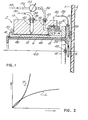
- FIGURE 1 shows a typical prior art mastering record head 2 for recording information on the light responsive coating 5 of a videodisc 4.
- the record head assembly which originates the sub-micron width tracks in the light responsive coating 5 (typically a thin metal coating, an ablative plastic coating, or photoresist coating), deposited on the near surface of a glass substrate 4.
- the objective lens assembly it has been found advantageous to pneumatically support the lens assembly and to incorporate pneumatic principles in effecting proper focus of the light beam on the videodisc surface.
- FIGURE 1 In the prior art example of FIGURE 1, for example, three different pneumatic systems acting in concert are shown.
- An inner objective lens casing 6, carrying the objective optics represented by lens 8, is coupled to an outer objective lens casing 10 by screwthreads 12.
- the inner casing 6 is screwed into outer casing 10 until a hard rubber ring 14 is firmly sandwiched between flanges at the entrance end of the objective lens.
- An annular forcing flange 16 extends laterally near the exit end of the objective lens assembly, while an end flange 18 of the outer objective lens casing 10 serves as a mounting structure for receiving foot plate 20 pivotal about pivoting members 22 (one shown) typically in the form of a ball joint contained within recessed pockets in plate-like members 18 and 20.
- Such pivoting members 22 are placed on opposite sides of the objective lens assembly, being in quadrature to a pair of diametrically opposed air outlets 24 receiving a source of input air 26 through tube 28 mounting bushing 30 and distributing cavity 32.
- a fixed air pressure of 45 psi is sufficient to create a pneumatic thrust bearing between foot plate 20 and the rotating disc substrate 4.
- the air exiting openings 24 placed on opposite sides of foot plate 20 thus create a relatively fixed resilient biasing force on the lens assembly relative to the housing to urge the lens assembly away from the substrate 4. Any distortions in the flatness of the disc as it passes by the head causes foot plate 20 to pivot about balls 22 and thus maintain constant spacing as the defect passes by.
- an inlet tube 34 receives positive air pressure indicated by arrow 35, the air passing through tube 34, mounting bushing 38, cavity 42, and into the spacing or gap between the objective lens outer casing 10 and housing 19.
- a third of the pneumatic systems employed in the read head of FIGURE 1 involves a tube 56 receiving positive air pressure indicated by arrow 58 leading to air pressure regulator 54.
- the air exiting regulator 54 is routed through tube 36, through mounting bushing 40, cavity 44, and into annular cavity 48 formed between flange 16 and housing 19. Adjusting the pressure regulator 54 changes the internal pressure within annular chamber 48, and this pressure acting between the fixed walls of housing 19 and the movable flange 16 defines a forcing piston arrangement for varying the axial position of the lens assembly within housing 19.
- the width W of flange 16 is on the order of 0.640 inches, while the gap G has a span of .001 inches.
- the ratio of the gap dimension divided by the axial length of the gap determines whether or not the fluid passing through the gap will exit the gap in laminar or turbulent flow. Analytical calculations can be made using what is referred to as the Reynolds criterion to produce a number above which substantiallyturbulent flow will result and another number below which substantially laminar flow will result.
- Reynolds numbers are dependent also on the viscosity and density of the fluid involved in the system, and since the present invention is concerned with the use of air as an operative fluid, and since the dimension of the gap G will naturally be made as small as possible without danger of flange 16 touching the inner wall of housing 19 due to manufacturing tolerances and uncontrollable lateral vibrations of the lens assembly, only the dimension W is variable to change the Reynolds number so as to obtain a smallest Reynolds number possible within the design constraint of the system.
- the Reynolds number equation in its simplest form can be stated as: where V and d are, respectively, the viscosity and density of the fluid involved, G is the gap span, and W is the axial length of the gap.
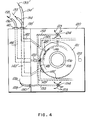
- FIGURE 3 the lens assembly is similarly constructed to that shown in FIGURE 1. That is, an inner lens casing 106 carries objective lens 108, and is threadedly received by outer casing 110. The two casings are locked together by a retainer bushing 115 having a lateral flange 114 bearing against the entrance end of the outer lens casing 110. Outer casing 110 has an end flange 118 facing a surface of foot plate 120 pivotally mounted with respect to end flange 118 about axis 117 on balls 122.
- a central land portion 121 surrounds the objective lens 108 leaving the remainder of the outer surface of foot plate 120 with a recessed area within which air indicated by arrows 123 in FIGURE 4 exit an opening 124 in the manner described in connection with the same function of the thrust bearing of FIGURE 1.
- a source of positive air pressure indicated by arrow 126 enters a tube 128 through mounting bushing 130 and through a distribution cavity 132 in foot plate 120.
- the function and operation of the thrust bearing is prior art knowledge and will not be detailed in this description.
- Locating chamber 148 to the center of the assembly is not a mere extension of the placement of the chamber 48 in FIGURE 1, since other considerations, such as the aforementioned loss of journal bearing surface, are involved.
- the outer peripheral surface of the lens casing 110 and the inner peripheral surface of the housing 119 are provided with shoulders making the parts of both the lens assembly and housing on either side of the annular chamber 148 of different diameters.
- sources of positive air pressure indicated by arrows 135 and 135' force air through tubes 134 and 134', through mounting bushings 138 and 138', through distribution cavities 142 and 142', and into the housing 119. All of the external connections and routing of air to housing 119 are shown in FIGURE 3 to take place within manifold 125.
- Air under positive pressure in passageways 142 and 142' is distributed to the central portion of the gaps G and G' as seen in FIGURE 3. After entering gaps G, G', the air providing a pneumatic journal bearing within gaps 146, 146', exit both ends of the gap, one end of each gap being exhausted to the atmosphere shown at 150 and 152, and other end of the gap exhausting into annular chamber 148.
- the air in chamber 148 is maintained at a pressure lower than that provided for the journal bearing, such that a pressure regulator 154 regulates the exhaust air pressure and maintains the appropriate forces acting between the housing l19 and casing 110 in the fashion of a pneumatic forcing piston to balance the oppositely directed forces against the lens assembly provided by the pneumatic thrust bearing between foot plate 120 and substrate 4.
- the exhaust air leaving chamber 148 is routed through distribution passageway 144, through mounting bushing 140, pipe 136, regulator 154, exit pipe 156, and to the atmosphere as shown at arrow 158.
- FIGURE 4 is drawn to show one possible routing arrangement for the air passageways supplying gaps 146 and 146', annular chamber 148, and passageways 132 for the thrust bearing. In order to avoid confusion, not all of the air passageways are shown in FIGURE 4.
- An example of air distribution around the periphery of gaps 146 and 146' is illustrated in FIGURE 4 by the provision of radially directed passageways 145 and 145' and feeder lines 143 and 143'.
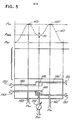
- FIGURE 5 shows a schematic representation of the principles of the invention at the bottom half therof and a graph of the pressure at the corresponding axial locations along the head assembly in the upper half of FIGURE 5.
- air exiting the ends of the assembly at 150 and 152 are at atmospheric pressure (PAT), while the peak pressures in the system occur in the points in gaps 146 and 146' where input pressure (PIN) enter passageways 142 and 142'.
- PIN input pressure
- FIGURE 5 shows the pressure dip point 151 of waveform 147.
- the graph of FIGURE 5 illustrates the higher pressure 149, 149' of the journal bearing air pressure sources relative to the pressure maintained within chamber 148 and, of course, atmospheric pressure at the ends of the assembly.
- input pressure in passageways 142 and 142' may be on the order of 28 psi, while the exhaust pressure adjusted by regulator 154 maintains a pressure in chamber 148 of approximately 10 psi resulting in a net force against the lens assembly relative to the housing of about 1 pound.
Landscapes
- Physics & Mathematics (AREA)
- Optics & Photonics (AREA)
- Optical Recording Or Reproduction (AREA)
- Sliding-Contact Bearings (AREA)
- Automatic Focus Adjustment (AREA)
Priority Applications (1)
| Application Number | Priority Date | Filing Date | Title |
|---|---|---|---|
| AT83110483T ATE45832T1 (de) | 1982-11-12 | 1983-10-20 | Fluessigkeitslager fuer axial bewegbaren kopf. |
Applications Claiming Priority (2)
| Application Number | Priority Date | Filing Date | Title |
|---|---|---|---|
| US440936 | 1982-11-12 | ||
| US06/440,936 US4594702A (en) | 1982-11-12 | 1982-11-12 | Fluid bearing for axially movable head |
Publications (3)
| Publication Number | Publication Date |
|---|---|
| EP0108960A2 true EP0108960A2 (de) | 1984-05-23 |
| EP0108960A3 EP0108960A3 (en) | 1986-01-15 |
| EP0108960B1 EP0108960B1 (de) | 1989-08-23 |
Family
ID=23750808
Family Applications (1)
| Application Number | Title | Priority Date | Filing Date |
|---|---|---|---|
| EP83110483A Expired EP0108960B1 (de) | 1982-11-12 | 1983-10-20 | Flüssigkeitslager für axial bewegbaren Kopf |
Country Status (7)
| Country | Link |
|---|---|
| US (1) | US4594702A (de) |
| EP (1) | EP0108960B1 (de) |
| JP (1) | JPS5992473A (de) |
| KR (1) | KR870002141B1 (de) |
| AT (1) | ATE45832T1 (de) |
| DE (1) | DE3380466D1 (de) |
| HK (1) | HK20791A (de) |
Families Citing this family (4)
| Publication number | Priority date | Publication date | Assignee | Title |
|---|---|---|---|---|
| JP2003223704A (ja) * | 2002-01-25 | 2003-08-08 | Fujitsu Ltd | 磁気ヘッドおよびデータ記録再生装置 |
| US11136667B2 (en) * | 2007-01-08 | 2021-10-05 | Eastman Kodak Company | Deposition system and method using a delivery head separated from a substrate by gas pressure |
| KR101063953B1 (ko) * | 2011-03-29 | 2011-09-14 | 장활석 | 간장통 이송시스템 |
| JP7179793B2 (ja) * | 2020-02-18 | 2022-11-29 | 株式会社東芝 | ディスク装置 |
Family Cites Families (10)
| Publication number | Priority date | Publication date | Assignee | Title |
|---|---|---|---|---|
| US3268877A (en) * | 1954-05-26 | 1966-08-23 | Floating magnetic transducing head | |
| US3030452A (en) * | 1958-01-29 | 1962-04-17 | Rca Corp | Regulation of head spacing by air bearing means |
| US3081682A (en) * | 1961-06-28 | 1963-03-19 | Ibm | Method and apparatus for obtaining and maintaining spacing of a transducer |
| GB1275906A (en) * | 1968-11-01 | 1972-06-01 | Barr & Stroud Ltd | Optical projection head |
| JPS5121783A (en) * | 1974-08-19 | 1976-02-21 | Hitachi Ltd | Handotaiuehano peretsutokahoho |
| US4006294A (en) * | 1975-05-27 | 1977-02-01 | Mca Disco-Vision, Inc. | Transducer head assembly with fluid bearing and head height control system |
| FR2312832A1 (fr) * | 1975-05-30 | 1976-12-24 | Thomson Brandt | Dispositif de stabilisation de disques souples, et notamment de video-disques, et appareil de lecture adapte a ce dispositif |
| US4030815A (en) * | 1975-10-31 | 1977-06-21 | Rca Corporation | Hydrostatic bearing apparatus |
| JPS52119927A (en) * | 1976-04-02 | 1977-10-07 | Hitachi Ltd | Device for automatic focus control |
| US4422169A (en) * | 1980-10-20 | 1983-12-20 | Discovision Associates | Lens assembly for a video recorder-playback machine |
-
1982
- 1982-11-12 US US06/440,936 patent/US4594702A/en not_active Expired - Lifetime
-
1983
- 1983-07-20 KR KR1019830003334A patent/KR870002141B1/ko not_active Expired
- 1983-08-12 JP JP58146790A patent/JPS5992473A/ja active Granted
- 1983-10-20 EP EP83110483A patent/EP0108960B1/de not_active Expired
- 1983-10-20 DE DE8383110483T patent/DE3380466D1/de not_active Expired
- 1983-10-20 AT AT83110483T patent/ATE45832T1/de not_active IP Right Cessation
-
1991
- 1991-03-21 HK HK207/91A patent/HK20791A/en not_active IP Right Cessation
Also Published As
| Publication number | Publication date |
|---|---|
| KR840006708A (ko) | 1984-12-01 |
| EP0108960B1 (de) | 1989-08-23 |
| US4594702A (en) | 1986-06-10 |
| DE3380466D1 (en) | 1989-09-28 |
| KR870002141B1 (ko) | 1987-12-12 |
| JPS5992473A (ja) | 1984-05-28 |
| ATE45832T1 (de) | 1989-09-15 |
| JPH0334624B2 (de) | 1991-05-23 |
| HK20791A (en) | 1991-03-28 |
| EP0108960A3 (en) | 1986-01-15 |
Similar Documents
| Publication | Publication Date | Title |
|---|---|---|
| US4636894A (en) | Recording head slider assembly | |
| EP0435495B1 (de) | Informationsaufzeichnungsgerät mit nicht-Newtonscher Flüssigkeit um den Wandler zu tragen | |
| EP0064390A1 (de) | Lager zur Stabilisierung der Bewegung eines magnetischen Aufzeichnungsträgers über einen Magnetkopf | |
| WO1997041556A3 (en) | Optical flying head with solid immersion lens having raised central surface facing media | |
| US4594702A (en) | Fluid bearing for axially movable head | |
| GB1561537A (en) | Hydrostatic bearing apparatus | |
| US3081682A (en) | Method and apparatus for obtaining and maintaining spacing of a transducer | |
| US6851861B2 (en) | Lubricant retention design for disk drive fluid dynamic bearing spindle motor | |
| US5488521A (en) | Information recording apparatus with a non-newtonian liquid bearing | |
| US6130802A (en) | Both ends open fluid dynamic bearing having a journal in combination with a conical bearing | |
| US4998175A (en) | Transducer-to-medium stabilizing device having a static pressure releasing arrangement for maintaining the transducer in a stable contact relationship with a recording medium | |
| US5798825A (en) | Air bearing imaging platen | |
| US6618226B2 (en) | Locally deformable sleeve on disk drive pivot assembly | |
| EP0951718A1 (de) | Flexible bernouilly-mediumstabilisierung für laserservosignalaufzeichnung | |
| JPH01271941A (ja) | 光ディスク原盤記録装置 | |
| JPS601422A (ja) | 原盤記録装置 | |
| JPH0252353B2 (de) | ||
| JPH0435833B2 (de) | ||
| JPH08273318A (ja) | 磁気記憶装置 | |
| JPS63231019A (ja) | 静圧軸受装置 | |
| JPH01245478A (ja) | 浮動ヘッドスライダ支持機構 | |
| JPH08203054A (ja) | 磁気ヘッドスライダ及び磁気ヘッドスライダ支持機構 | |
| JP2001351215A (ja) | ディスク記録再生装置のスライダ | |
| JPH0242689A (ja) | 情報記録再生装置 | |
| JPH03119511A (ja) | スライダ付ヘッド |
Legal Events
| Date | Code | Title | Description |
|---|---|---|---|
| PUAI | Public reference made under article 153(3) epc to a published international application that has entered the european phase |
Free format text: ORIGINAL CODE: 0009012 |
|
| 17P | Request for examination filed |
Effective date: 19831223 |
|
| AK | Designated contracting states |
Designated state(s): AT BE CH DE FR GB IT LI LU NL SE |
|
| PUAL | Search report despatched |
Free format text: ORIGINAL CODE: 0009013 |
|
| AK | Designated contracting states |
Designated state(s): AT BE CH DE FR GB IT LI LU NL SE |
|
| 17Q | First examination report despatched |
Effective date: 19870722 |
|
| GRAA | (expected) grant |
Free format text: ORIGINAL CODE: 0009210 |
|
| AK | Designated contracting states |
Kind code of ref document: B1 Designated state(s): AT BE CH DE FR GB IT LI LU NL SE |
|
| PG25 | Lapsed in a contracting state [announced via postgrant information from national office to epo] |
Ref country code: SE Effective date: 19890823 Ref country code: NL Effective date: 19890823 Ref country code: BE Effective date: 19890823 |
|
| REF | Corresponds to: |
Ref document number: 45832 Country of ref document: AT Date of ref document: 19890915 Kind code of ref document: T |
|
| REF | Corresponds to: |
Ref document number: 3380466 Country of ref document: DE Date of ref document: 19890928 |
|
| PG25 | Lapsed in a contracting state [announced via postgrant information from national office to epo] |
Ref country code: LU Free format text: LAPSE BECAUSE OF NON-PAYMENT OF DUE FEES Effective date: 19891031 |
|
| ITF | It: translation for a ep patent filed | ||
| ET | Fr: translation filed | ||
| NLV1 | Nl: lapsed or annulled due to failure to fulfill the requirements of art. 29p and 29m of the patents act | ||
| PLBE | No opposition filed within time limit |
Free format text: ORIGINAL CODE: 0009261 |
|
| STAA | Information on the status of an ep patent application or granted ep patent |
Free format text: STATUS: NO OPPOSITION FILED WITHIN TIME LIMIT |
|
| 26N | No opposition filed | ||
| ITTA | It: last paid annual fee | ||
| REG | Reference to a national code |
Ref country code: GB Ref legal event code: IF02 |
|
| PGFP | Annual fee paid to national office [announced via postgrant information from national office to epo] |
Ref country code: FR Payment date: 20021002 Year of fee payment: 20 |
|
| PGFP | Annual fee paid to national office [announced via postgrant information from national office to epo] |
Ref country code: AT Payment date: 20021003 Year of fee payment: 20 |
|
| PGFP | Annual fee paid to national office [announced via postgrant information from national office to epo] |
Ref country code: CH Payment date: 20021004 Year of fee payment: 20 |
|
| PGFP | Annual fee paid to national office [announced via postgrant information from national office to epo] |
Ref country code: GB Payment date: 20021016 Year of fee payment: 20 |
|
| PGFP | Annual fee paid to national office [announced via postgrant information from national office to epo] |
Ref country code: DE Payment date: 20021031 Year of fee payment: 20 |
|
| PG25 | Lapsed in a contracting state [announced via postgrant information from national office to epo] |
Ref country code: LI Free format text: LAPSE BECAUSE OF EXPIRATION OF PROTECTION Effective date: 20031019 Ref country code: GB Free format text: LAPSE BECAUSE OF EXPIRATION OF PROTECTION Effective date: 20031019 Ref country code: CH Free format text: LAPSE BECAUSE OF EXPIRATION OF PROTECTION Effective date: 20031019 |
|
| PG25 | Lapsed in a contracting state [announced via postgrant information from national office to epo] |
Ref country code: AT Free format text: LAPSE BECAUSE OF EXPIRATION OF PROTECTION Effective date: 20031020 |
|
| REG | Reference to a national code |
Ref country code: GB Ref legal event code: PE20 |
|
| REG | Reference to a national code |
Ref country code: CH Ref legal event code: PL |