EP0108930A2 - Overload protection in couplings - Google Patents
Overload protection in couplings Download PDFInfo
- Publication number
- EP0108930A2 EP0108930A2 EP83110148A EP83110148A EP0108930A2 EP 0108930 A2 EP0108930 A2 EP 0108930A2 EP 83110148 A EP83110148 A EP 83110148A EP 83110148 A EP83110148 A EP 83110148A EP 0108930 A2 EP0108930 A2 EP 0108930A2
- Authority
- EP
- European Patent Office
- Prior art keywords
- overload protection
- suspension section
- protection according
- annular space
- section
- Prior art date
- Legal status (The legal status is an assumption and is not a legal conclusion. Google has not performed a legal analysis and makes no representation as to the accuracy of the status listed.)
- Granted
Links
Images


Classifications
-
- F—MECHANICAL ENGINEERING; LIGHTING; HEATING; WEAPONS; BLASTING
- F16—ENGINEERING ELEMENTS AND UNITS; GENERAL MEASURES FOR PRODUCING AND MAINTAINING EFFECTIVE FUNCTIONING OF MACHINES OR INSTALLATIONS; THERMAL INSULATION IN GENERAL
- F16D—COUPLINGS FOR TRANSMITTING ROTATION; CLUTCHES; BRAKES
- F16D7/00—Slip couplings, e.g. slipping on overload, for absorbing shock
- F16D7/04—Slip couplings, e.g. slipping on overload, for absorbing shock of the ratchet type
- F16D7/048—Slip couplings, e.g. slipping on overload, for absorbing shock of the ratchet type with parts moving radially between engagement and disengagement
-
- F—MECHANICAL ENGINEERING; LIGHTING; HEATING; WEAPONS; BLASTING
- F16—ENGINEERING ELEMENTS AND UNITS; GENERAL MEASURES FOR PRODUCING AND MAINTAINING EFFECTIVE FUNCTIONING OF MACHINES OR INSTALLATIONS; THERMAL INSULATION IN GENERAL
- F16D—COUPLINGS FOR TRANSMITTING ROTATION; CLUTCHES; BRAKES
- F16D7/00—Slip couplings, e.g. slipping on overload, for absorbing shock
- F16D7/04—Slip couplings, e.g. slipping on overload, for absorbing shock of the ratchet type
- F16D7/06—Slip couplings, e.g. slipping on overload, for absorbing shock of the ratchet type with intermediate balls or rollers
- F16D7/10—Slip couplings, e.g. slipping on overload, for absorbing shock of the ratchet type with intermediate balls or rollers moving radially between engagement and disengagement
Definitions
- the invention relates to an overload protection on couplings, with drive and output elements arranged concentrically to one another and with a driving body provided in the intermediate space of these elements and interacting with a spring.
- Overload safety devices are known in which the cylindrical drive body is pivoted on one arm of a double-armed lever and is immersed in a notch-like recess in a ring surrounding it ("Hütte", Ingenieur practice Taschenbuch II, 27th edition).
- a tension spring acts on the other arm of the lever and loads the entraining body in the direction of engagement. If the limit torque is exceeded, the entrainment body disengages from the recess and thus separates the input and output.
- This configuration is complex in its construction and requires a larger space. It is therefore not very suitable for use in small motor-driven devices.
- the object of the invention is based on the design of an overload protection of the type required in a technically simple manner so that it works reliably in a small design.
- This object is achieved in that the uncoupling position is achieved by bending a suspension section crossing the intermediate space.
- the electric motor and the drive elements are therefore protected while increasing the life of the device. After eliminating the source of the error, the overload protection is ready for use without special handling.
- the transmission range of the clutch can be determined by the position and design of the suspension section. A lubricant may also be added.
- the space between the drive and driven element is designed as an annular space, the cross section of which is reduced at least at one point by means of a suspension section to a dimension smaller than the diameter of the entraining body rotating in the annular space.
- the driver body can be designed as a rolling body. Different types of rolling elements can be used. These can have the shape of a barrel, roller or ball, for example.
- the suspension section could also be adjusted.
- suspension section is formed by a leaf spring arranged in the form of a secant to the annular space. This can be created inexpensively and easily accommodated in terms of assembly technology.
- a variant is characterized in that several leaf springs lying at an angle to one another are provided one behind the other in the circumferential direction of the annular space.
- the entrainment body is positively held in a clamping position after the switch-on jerk.
- the arrangement of the leaf spring can be such that the reduction in cross section increases.
- leaf spring lies in a slot in the wall of a sleeve forming the annular space wall with its inner surface, which forms the drive element.
- suspension section from a leaf spring that extends spirally into the annular space for bouncing-free coupling of the entrainment body.
- An advantageous embodiment also consists in the fact that an outwardly directed evasive space for the entrainment body is arranged downstream of the reduced-section location. After the limit torque has been exceeded, the input and output elements still run at the input speed. However, immediately after disengaging or overcoming the suspension section, the entrainment body is pressed against the outer raceway by centrifugal force, enters the evasive space and is therefore no longer in contact with the output element and, in this position, rotates freely with the drive. After switching off the device, the entrainment body is still in the escape room. Only the switch-on jerk, caused by the inertia of the entrainment body, leads to a renewed entrainment of the same and thus the clutch closing.
- Another design in which the production is further simplified, less assembly work and a more wear-free operation is achieved, is characterized in that the entrainment body is formed by a cam assigned to the drive shaft, the apex height of which is greater than the dimension of the Annulus in its reduced area.
- cam is designed as a molded part of a ring arranged on the drive shaft in a rotationally fixed manner.
- the suspension section is designed as a bimetallic strip in such a way that the resulting from the grinding movement between the suspension section and the cam Heating bends the suspension section in the uncoupling position. This heating only takes place when the cam slips repeatedly under the bimetal strip. The transmission system is then completely disengaged until the bimetal strip has cooled down again.
- the bimetallic strip is arranged so that the more expanding metal strip faces away from the cam. Both ends of the bimetal strip can be firmly anchored. However, it turns out to be more favorable if only one end is fixed and the other end is movable.
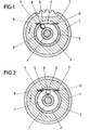
- the number 1 denotes a gearwheel which is rotated in the direction of arrow x by a gear unit (not shown) of a small electrical device.
- This gearwheel 1 is non-rotatably seated on a drive element 2 which is formed by a bush and which is arranged concentrically with an annular output element 4 while leaving an annular space 3.
- the cross section of the annular space 3 is reduced at one point by means of a suspension section 5.
- the suspension section 5 is formed by a leaf spring arranged in a secant shape relative to the annular space 3. This lies in a slot 6 of the wall of the sleeve 2 forming the annular space wall 2 'with its inner surface. The slot 6 continues into that Gear 1 reaching insertion niches 7 for the ends 5 'of the leaf spring 5 on.
- a driving body 8 which is adapted to this in diameter.
- the latter is designed as a ball.
- the entrainment body 8 reaches the wedging position between the suspension section 5 and the output element 4 as shown in FIG. 1 when the switch-on jerk occurs. Then a slip-free transmission of the drive power to the output element 4 occurs achieved by a greater resistance on the output element 4, the entrainment body 8 overcomes the suspension section 5 by pressing it into the slot 6 according to FIG. Then the entrainment body 8 again enters the annular space 3 and, due to its inertia, returns to the position shown in FIG. 1 and again overcomes the area of the annular space 3 which is reduced in cross-section by the leaf spring serves.
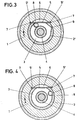
- the structure of the second embodiment shown in FIGS. 3 and 4 corresponds essentially to that of the first embodiment.
- the same components therefore have the same reference symbols.
- the area reduced by the leaf spring 5 is followed by an outwardly directed escape space 9 for the spherical entrainment body 8.
- the escape space 9 is located in the annular space wall 2 'and is adapted to the curvature of the entrainment body 8.
- the entrainment body 8 arrives in the evacuation space 9 and remains there due to centrifugal force of the rotating bush 2.
- the evacuation space 9 is dimensioned so deep that the entrainment body receives no contact with the circumferential surface of the ring-like output element 4. If the device is stopped when a limit value is exceeded and switched on again, it leaves of the switch-on jerk of the entraining body 8, the escape space 9 and reaches the entraining position according to FIG. 3.
- FIGS. 5 and 6 The third embodiment illustrated in FIGS. 5 and 6 is designed similarly to the previous ones. There are now three leaf springs 10, 11 and 12 lying at an angle to one another. Each leaf spring 10, 11, 12 has its own escape slot 13, 14, 15. Both the leaf springs 10-12 and the escape slots 13-15 have different lengths. In this way it is possible for the shortest leaf spring 10 to bring about a smaller reduction in the cross section of the annular space 3. The subsequent leaf springs 11, 12 lead to a step-like cross-sectional reduction of the annular space 3, the cross-sectional reduction being greatest in the area of the leaf spring 12. The driving body 8 must therefore, as shown in Fig. 6, overcome the successive cross-sectional reductions. If he has completed all the cross-sectional reductions caused by the leaf springs 10-12, he arrives in a subordinate escape space 9.
- the suspension section is formed by a leaf spring 16 which extends spirally into the annular space 3 in such a way that the reduction in cross section increases towards the end 16 'of the leaf spring.
- the other end 16 ′′ lies in a radial groove 17 of the sleeve-shaped drive element 18.
- the greater the resistance the further the entrainment body 8 reaches the free end 16 ′ of the leaf spring 16. If the section modulus on the output element 4 is too great, it is overcome the entrainment body 8 completely reduces the cross-section caused by the leaf spring 16, the leaf spring 16 inevitably immersing in the arch slot 19 of the bush 18 assigned to it, see FIG. 8.
- the drive shaft driven by a device motor is designated by the number 20.
- a ring 23 is seated on this drive shaft 20 in a non-rotatable manner.
- a feather key 24 is used for non-rotatability.
- the ring 23 forms an annular space 26 in connection with an output element 25 which is concentrically disposed therewith.
- the suspension section 27 is formed by a leaf spring arranged in the form of a secant to the annular space 26. This lies with its ends 27 'in slots 28 of the inner sleeve 25' of the output element 25.
- the cross-sectional reduction of the annular space 26 is dimensioned so large that the ring 23 is adjacent to the suspension section 27 with its peripheral surface.
- the suspension section 27 interacts with a cam 29, which starts from the ring 23 and forms the entrainment body, and is formed by shaping the ring 23.
- the cam 29 extends at the level of the feather key 24.
- the apex height y of the cam is greater than the dimension of the annular space 26 in its area reduced by the suspension section 27.
- the cam 29 first comes into contact with the suspension section 27 and takes the driven element 25 with it. If the maximum force limited by the apex height of the cam and spring strength is exceeded, the case according to FIG. 10 occurs, with the cam 29 deflecting the suspension section 27. The cam 29 then moves away from the suspension section 27 in the direction of rotation. Until the cam 29 contacts the suspension section 27 again, there is no contact between these two parts. As it continues to rotate, the cam 29 comes into contact with the suspension portion 27 again and the transmission system is in engagement again. If the load torque has not yet dropped below the maximum permissible value, the process described above is repeated. Here This creates a noise that draws the user's attention to an excessive load on the device equipped with the coupling.
- a further modification is possible in that a bimetal strip is used instead of the suspension section 27 in such a way that its more expanding metal strip faces away from the cam 29. Both ends of the bimetal strip can then be firmly anchored to the output element 25. It turns out to be a cheaper solution to firmly anchor only one end and make the other end movable. If the limit torque is exceeded, the constant slippage of the cam on the underside of the bimetallic strip then heats it up, so that it then bends in the outward direction. Then there is no contact between the cam and the bimetallic strip. The transmission system is now completely disengaged until the bimetal strip has cooled down again.
- cams and suspension sections instead of two cams and two suspension sections, it would also be possible to provide more cams and suspension sections in the same angular distribution. Then larger torques can be added transfer smaller loads from cams and suspension sections.
Landscapes
- Engineering & Computer Science (AREA)
- General Engineering & Computer Science (AREA)
- Mechanical Engineering (AREA)
- One-Way And Automatic Clutches, And Combinations Of Different Clutches (AREA)
- Mechanical Operated Clutches (AREA)
Abstract
Die Erfindung betrifft eine Überlastsicherung an Kupplungen, mit konzentrisch zueinander angeordneten Antriebs- und Abtriebselementen und mit im Zwischenraum dieser Elemente vorgesehenem, mit einer Feder zusammenwirkendem Mitnahme-Körper (8) und schlägt zwecks Erzielung einer herstellungstechnisch einfachen und kleinen Bauform bei zuverlässiger Arbeitsweise vor, daß die Entkupplungsstellung durch Ausbiegung eines den Zwischenraum (3) kreuzenden Federungsabschnitts (5) erzielt ist.
Description
Die Erfindung betrifft eine Überlastsicherung an Kupplungen, mit konzentrisch zueinander angeordneten Antriebs- und Abtriebselementen und mit im Zwischenraum dieser Elemente vorgesehenem, mit einer Feder zusammenwirkendem Mitnahme-Körper.The invention relates to an overload protection on couplings, with drive and output elements arranged concentrically to one another and with a driving body provided in the intermediate space of these elements and interacting with a spring.
Es sind Überlastsicherungen bekannt, bei denen der zylindrisch gestaltete Mitnahme-Körper drehbar an dem einen Arm eines doppelarmigen Hebels angelenkt ist und in eine kerbartige Vertiefung eines ihn umgebenden Ringes eintaucht ("Hütte", des Ingenieurs-Taschenbuch II, 27. Auflage). An dem anderen Arm des Hebels greift eine Zugfeder an, die den Mitnahme-Körper in Eingriffsrichtung belastet. Bei Überschreiten des Grenzmoments gelangt der Mitnahme-Körper außer Eingriff mit der Vertiefung und trennt damit den An- und Abtrieb. Diese Ausgestaltung ist aufwendig in ihrem Aufbau und verlangt einen größeren Raumbedarf. Daher ist sie wenig geeignet, in motorisch betriebene Kleingeräte eingesetzt zu werden.Overload safety devices are known in which the cylindrical drive body is pivoted on one arm of a double-armed lever and is immersed in a notch-like recess in a ring surrounding it ("Hütte", Ingenieurbüro Taschenbuch II, 27th edition). A tension spring acts on the other arm of the lever and loads the entraining body in the direction of engagement. If the limit torque is exceeded, the entrainment body disengages from the recess and thus separates the input and output. This configuration is complex in its construction and requires a larger space. It is therefore not very suitable for use in small motor-driven devices.
Dem Gegenstand der Erfindung liegt die Aufgabe zugrunde, eine Überlastsicherung der vorausgesetzten Art in herstellungstechnisch einfacher Weise so auszugestalten, daß sie bei kleiner Bauform zuverlässig arbeitet.The object of the invention is based on the design of an overload protection of the type required in a technically simple manner so that it works reliably in a small design.
Gelöst wird diese Aufgabe dadurch, daß die Entkupplungsstellung durch Ausbiegung eines den Zwischenraum kreuzenden Federungsabschnitts erzielt ist.This object is achieved in that the uncoupling position is achieved by bending a suspension section crossing the intermediate space.
Die Vorteile der erfindungsgemäßen Ausgestaltung bestehen im wesentlichen in der besonders einfachen Ausgestaltung und in der räumlich kleinen Bauform. Daher läßt sich diese Überlastsicherung an Kupplungen mit Vorteil in motorisch betriebene Elektrokleingeräte einsetzen. Bis zu einem bestimmten Durchgangsmoment wird die Leistung schlupffrei übertragen. Wird ein vorgegebenes Grenzmoment überschritten, drückt der Mitnahme-Körper den den Zwischenraum kreuzenden Federungsabschnitt zur Seite und kann dann ohne Mitnahmewirkung umlaufen. Bei weiterem Umlauf kann der Mitnahme-Körper den Federungsabschnitt unverzüglich wieder überwinden, falls das Überlastdrehmoment noch nicht unter den maximal zulässigen Wert abgesunken sein sollte. Das dabei auftretende Anschlaggeräusch zwischen Mitnahme-Körper und Federungsabschnitt dient als akkustisches Warnsignal für den Gerätebenutzer. Er wird dadurch darauf aufmerksam gemacht, das Gerät abzustellen. Der Elektromotor und die Antriebselemente werden daher geschützt unter Erhöhung der Lebensdauer des Geräts. Nach Beseitigung der Fehlerquelle ist die Überlastsicherung ohne besondere Handhabung einsatzbereit. Der Übertragungsbereich der Kupplung ist bestimmbar durch Lage und Ausbildung des Federungsabschnitts. Eventuell kann auch ein Schmiermittel hinzugefügt werden.The advantages of the configuration according to the invention consist essentially in the particularly simple configuration and in the spatially small design. Therefore, this overload protection on couplings can be used with advantage in small motorized electrical devices. Up to a certain moment of passage, the power is transmitted without slip. If a predetermined limit torque is exceeded, the entrainment body pushes the suspension section crossing the intermediate space to the side and can then rotate without an entrainment effect. With further circulation, the entrainment body can immediately overcome the suspension section again if the overload torque has not yet dropped below the maximum permissible value. The impact noise that occurs between the driver body and the suspension section serves as an acoustic warning signal for the device user. This will alert the user to turning off the device. The electric motor and the drive elements are therefore protected while increasing the life of the device. After eliminating the source of the error, the overload protection is ready for use without special handling. The transmission range of the clutch can be determined by the position and design of the suspension section. A lubricant may also be added.
Eine vorteilhafte Weiterbildung besteht darin, daß der Zwischenraum zwischen Antriebs- und Abtriebselement als Ringraum ausgestaltet ist, dessen Querschnitt mindestens an einer Stelle mittels eines Federungsabschnitts reduziert ist auf ein Maß kleiner als der Durchmesser des im Ringraum umlaufenden Mitnahme-Körpers. Demgemäß können die Mitnahme-Körper als Rollkörper ausgebildet sein. Es lassen sich unterschiedlich geartete Rollkörper einsetzen. Diese können bspw. die Form einer Tonne, Walze oder Kugel besitzen. Zwecks Variation der Mitnahmeverhältnisse könnte auch eine Nachstellbarkeit des Federungsabschnitts vorgesehen sein.An advantageous development is that the space between the drive and driven element is designed as an annular space, the cross section of which is reduced at least at one point by means of a suspension section to a dimension smaller than the diameter of the entraining body rotating in the annular space. Accordingly, the driver body can be designed as a rolling body. Different types of rolling elements can be used. These can have the shape of a barrel, roller or ball, for example. For the purpose of varying the entrainment conditions, the suspension section could also be adjusted.
Eine besonders günstige Ausgestaltung ist darin zu sehen, daß der Federungsabschnitt von einer sekantenförmig zum Ringraum angeordneten Blattfeder gebildet ist. Diese läßt sich kostengünstig erstellen und montagetechnisch einfach unterbringen.A particularly favorable embodiment can be seen in the fact that the suspension section is formed by a leaf spring arranged in the form of a secant to the annular space. This can be created inexpensively and easily accommodated in terms of assembly technology.
Eine Variante zeichnet sich dadurch aus, mehrere winklig zueinander liegende Blattfedern in Umfangsrichtung des Ringraumes hintereinanderliegend vorzusehen. Hierdurch wird der Mitnahme-Körper nach dem Einschaltruck formschlüssig in einer Klemmlage gehalten. Die Anordnung der Blattfeder kann dabei so sein, daß die Querschnittsreduzierung zunimmt.A variant is characterized in that several leaf springs lying at an angle to one another are provided one behind the other in the circumferential direction of the annular space. As a result, the entrainment body is positively held in a clamping position after the switch-on jerk. The arrangement of the leaf spring can be such that the reduction in cross section increases.
Eine besonders einfache Unterbringung der Blattfeder ist darin zu sehen, daß sie in einem Schlitz der Wandung einer mit deren Innenfläche die Ringraumwand bildenden Büchse einliegt, welche das Antriebselement bildet.A particularly simple accommodation of the leaf spring can be seen in the fact that it lies in a slot in the wall of a sleeve forming the annular space wall with its inner surface, which forms the drive element.
Weiterhin ist es möglich, den Federungsabschnitt von einer sich spiralförmig in den Ringraum erstreckenden Blattfeder zu bilden zum prellfreien Einkuppeln des Mitnahme-Körpers.Furthermore, it is possible to form the suspension section from a leaf spring that extends spirally into the annular space for bouncing-free coupling of the entrainment body.
Auch besteht eine vorteilhafte Ausgestaltung noch darin, daß der querschnittsreduzierten Stelle ein nach außen gerichteter Ausweichraum für den Mitnahme-Körper nachgeordnet ist. Nach dem Überschreiten des Grenzmoments laufen die Antriebs- und Abtriebselemente zunächst noch mit der Antriebsdrehzahl um. Doch unmittelbar nach dem Auskuppeln bzw. Überwinden des Federungsabschnitts wird der Mitnahme-Körper durch die Fliehkraft gegen die äußere Laufbahn gedrückt, gelangt in den Ausweichraum und hat daher keinen Kontakt mehr zum Abtriebselement und läuft in dieser Position mit dem Antrieb völlig frei um. Nach dem Abschalten des Geräts liegt der Mitnahme-Körper noch in dem Ausweichraum. Erst der Einschaltruck, bedingt durch die Massenträgheit des Mitnahme-Körpers, führt zu einer erneuten Mitnahme desselben und somit Schließen der Kupplung.An advantageous embodiment also consists in the fact that an outwardly directed evasive space for the entrainment body is arranged downstream of the reduced-section location. After the limit torque has been exceeded, the input and output elements still run at the input speed. However, immediately after disengaging or overcoming the suspension section, the entrainment body is pressed against the outer raceway by centrifugal force, enters the evasive space and is therefore no longer in contact with the output element and, in this position, rotates freely with the drive. After switching off the device, the entrainment body is still in the escape room. Only the switch-on jerk, caused by the inertia of the entrainment body, leads to a renewed entrainment of the same and thus the clutch closing.
Eine andere Bauform, bei welcher die Herstellung weiter vereinfacht ist, ein geringerer Montageaufwand auftritt und eine verschleißfreiere Arbeitsweise erzielt ist, zeichnet sich dadurch aus, daß der Mitnahme-Körper von einem der Antriebswelle zugeordneten Nocken gebildet ist, dessen Scheitelhöhe größer ist als das Maß des Ringraumes in seinem querschnittsreduzierten Bereich. Es liegen bei dieser Bauform bessere Mitnahmeverhältnisse vor wegen der größeren Mitnahmefläche zwischen Nocken und Federungsabschnitt in der Kupplungsstellung. Wird die durch die Scheitelhöhe des Nockens, die Anordnung des Federungsabschnitts und Federstärke desselben begrenzte Maximalkraft überschritten, bewegt sich der Nocken nach Ausbiegen des Federungsabschnitts in Drehrichtung von diesem fort. Bis zum erneuten Kontakt des Nockens mit dem Federungsabschnitt erfolgt dann keine Berührung der beiden Teile, so daß das Übertragungssystem reibungsfrei weiterläuft. Bei seinem weiteren Umlauf kommt der Nocken wieder mit dem Federungsabschnitt in Berührung, und das Übertragungssystem ist wieder in Eingriff. Sollte das Lastdrehmoment dann noch nicht unter den maximal zulässigen Wert abgesunken sein, so wiederholt sich der vorbeschriebene Vorgang. Das sich dabei ergebende Geräusch macht den Benutzer auf eine zu hohe Last aufmerksam, was ihn veranlaßt, das mit der entsprechenden Überlastsicherung ausgestattete Gerät stillzusetzen. Da der Nocken gemeinsam mit der Antriebswelle umläuft, arbeitet die Überlastsicherung mit geringerem Verschleiß. Die wesentliche Reibung entsteht ausschließlich im Bereich zwischen Nocken und Federungsabschnitt.Another design, in which the production is further simplified, less assembly work and a more wear-free operation is achieved, is characterized in that the entrainment body is formed by a cam assigned to the drive shaft, the apex height of which is greater than the dimension of the Annulus in its reduced area. With this design there are better driving conditions because of the larger driving area between the cam and the suspension section in the coupling position. If the maximum force, which is limited by the apex height of the cam, the arrangement of the suspension section and the spring strength thereof, is exceeded, the cam moves away from the suspension section after it has been bent out in the direction of rotation. Until the cam comes into contact with the suspension section again, there is no contact between the two parts, so that the transmission system continues to run smoothly. As it continues to rotate, the cam contacts the suspension portion again and the transmission system is engaged again. If the load torque has not yet dropped below the maximum permissible value, the process described above is repeated. The resulting noise draws the user's attention to an excessive load, which causes him to shut down the device equipped with the appropriate overload protection. Since the cam rotates together with the drive shaft, the overload protection works with less wear. The main friction occurs exclusively in the area between the cam and the suspension section.
Herstellungstechnische Vorteile ergeben sich dabei dadurch, wenn der Nocken als Ausformung eines auf der Antriebswelle drehfest angeordneten Ringes ausgebildet ist.Manufacturing advantages result from the fact that the cam is designed as a molded part of a ring arranged on the drive shaft in a rotationally fixed manner.
Eine weitere Bauform ist noch darin zu sehen, daß der Federungsabschnitt als Bimetallstreifen gestaltet ist derart, daß die aus der Schleifbewegung zwischen Federungsabschnitt und Nocken resultierende Erwärmung den Federungsabschnitt in die Entkupplungsstellung ausbiegt. Diese Erwärmung findet erst bei wiederholtem Durchrutschen des Nockens unter dem Bimetallstreifen statt. Das Übertragungssystem ist dann völlig ausgekuppelt, und zwar so lange, bis der Bimetallstreifen sich wieder abgekühlt hat. Der Bimetallstreifen wird so angeordnet, daß der sich mehr ausdehnende Metallstreifen dem Nocken abgewandt ist. Beide Enden des Bimetallstreifens können fest verankert sein. Günstiger erweist es sich jedoch, wenn nur ein Ende festgelegt und das andere Ende verschieblich ist.Another design can be seen in the fact that the suspension section is designed as a bimetallic strip in such a way that the resulting from the grinding movement between the suspension section and the cam Heating bends the suspension section in the uncoupling position. This heating only takes place when the cam slips repeatedly under the bimetal strip. The transmission system is then completely disengaged until the bimetal strip has cooled down again. The bimetallic strip is arranged so that the more expanding metal strip faces away from the cam. Both ends of the bimetal strip can be firmly anchored. However, it turns out to be more favorable if only one end is fixed and the other end is movable.
Nachstehend werden sechs Ausführungsbeispiele der Erfindung anhand der Fig. 1-12 erläutert. Es zeigt
- Fig. 1 einen Querschnitt durch eine Kupplung gemäß der ersten Ausführungsform bei in Kupplungsstellung befindlichem Mitnahme-Körper,
- Fig. 2 eine der Fig. 1 entsprechende Darstellung, wobei der Mitnahme-Körper den Federungsabschnitt ausdrückt,
- Fig. 3 einen Querschnitt durch die zweite Ausführungsform einer Kupplung mit in Kupplungsstellung befindlichem Mitnahme-Körper,
- Fig. 4 die der Fig. 3 entsprechende Darstellung, wobei der Mitnahme-Körper nach Überwinden des Federungsabschnitts in den diesem nachgeordneten Ausweichraum eingetreten ist,
- Fig. 5 die dritte Ausführungsform einer Kupplung im Schnitt, welche mehrere winklig zueinander liegende Blattfedern besitzt, und zwar bei in Kupplungsstellung befindlichem Mitnahme-Körper,
- Fig. 6 den der Fig. 5 entsprechenden Schnitt, wobei der Mitnahme-Körper einen Federungsabschnitt ausdrückt,
- Fig. 7 einen Querschnitt durch die Kupplung gemäß der vierten Ausführungsform, bei welcher der Federungsabschnitt von einer sich spiralförmig in den Ringraum erstreckenden Blattfeder gebildet ist, die Kupplungsstellung betreffend,
- Fig. 8 eine der Fig. 7 entsprechende Darstellung während des Auskuppelns bei Erreichen des Grenzmoments,
- Fig. 9 einen Querschnitt durch die Kupplung gemäß der ersten Ausführungsform bei in Kupplungsstellung befindlichem Nocken,
- Fig. 10 eine der Fig. 9 entsprechende Darstellung, wobei der Nocken den Federungsabschnitt ausdrückt,
- Fig. 11 einen Querschnitt durch die sechste Ausführungsform der Kupplung, wobei zwei den Ringraum kreuzende Federungsabschnitte und an der Antriebswelle zwei Nocken vorgesehen sind gemäß der Kupplungsstellung und
- Fig. 12 eine der Fig. 11 entsprechende Darstellung, wobei die Nocken die Federungsabschnitte ausgebogen haben.
- 1 shows a cross section through a coupling according to the first embodiment with the driving body in the coupling position,
- 2 shows a representation corresponding to FIG. 1, the driving body expressing the suspension section,
- 3 shows a cross section through the second embodiment of a coupling with a driving body located in the coupling position,
- FIG. 4 shows the representation corresponding to FIG. 3, the entrainment body having entered the escape space downstream of the suspension section,
- 5 shows the third embodiment of a coupling in section, which has a plurality of leaf springs lying at an angle to one another, specifically with the driving body in the coupling position,
- 6 the section corresponding to FIG. 5, the driving body expressing a suspension section,
- 7 shows a cross section through the coupling according to the fourth embodiment, in which the suspension section is formed by a leaf spring which extends spirally into the annular space and relates to the coupling position,
- 8 shows a representation corresponding to FIG. 7 during the disengagement when the limit torque is reached,
- 9 shows a cross section through the clutch according to the first embodiment with the cam in the clutch position,
- 10 shows a representation corresponding to FIG. 9, the cam expressing the suspension section,
- 11 shows a cross section through the sixth embodiment of the clutch, two suspension sections crossing the annular space and two cams being provided on the drive shaft in accordance with the clutch position and
- Fig. 12 is a representation corresponding to FIG. 11, wherein the cams have bent out the suspension sections.
Gemäß der in den Fig. 1 und 2 dargestellten ersten Ausführungsform ist mit der Ziffer 1 ein Zahnrad bezeichnet, welches von einer nicht dargestellten Getriebeeinheit eines elektrischen Kleingerätes in Pfeilrichtung x in Umdrehung versetzt wird. Dieses Zahnrad 1 sitzt drehfest auf einem von einer Büchse gebildeten Antriebselement 2, welches unter Belassung eines Ringraumes 3 konzentrisch zu einem ringartigen Abtriebselement 4 angeordnet ist. Der Querschnitt des Ringraumes 3 ist an einer Stelle mittels eines Federungsabschnitts 5 reduziert. Im vorliegenden Fall ist der Federungsabschnitt 5 von einer sekantenförmig zum Ringraum 3 angeordneten Blattfeder gebildet. Diese liegt in einem Schlitz 6 der Wandung der mit ihrer Innenfläche die Ringraumwand 2' bildenden Büchse 2 ein. Der Schlitz 6 setzt sich bis in das Zahnrad 1 reichende Einstecknischen 7 für die Enden 5' der Blattfeder 5 fort.According to the first embodiment shown in FIGS. 1 and 2, the
In dem Ringraum 3 liegt ein diesem im Durchmesser angepaßter Mitnahme-Körper 8 ein. Letzterer ist als Kugel ausgebildet.In the
Wird das Zahnrad 1 in Pfeilrichtung x angetrieben, so gelangt der Mitnahme-Körper 8 beim Einschaltruck in die verkeilende Stellung zwischen Federungsabschnitt 5 und Abtriebselement 4 gemäß Fig. 1. Dann erfolgt eine schlupffreie Übertragung der Antriebsleistung auf das Abtriebselement 4. Wird das Grenzmoment, bspw. durch einen größeren Widerstand am Abtriebselement 4 erreicht, so überwindet der Mitnahme-Körper 8 den Federungsabschnitt 5, indem er diesen gemäß Fig. 2 in den Schlitz 6 ausdrückt. Danach gelangt der Mitnahme-Körper 8 erneut in den Ringraum 3 und zufolge seiner Trägheit wieder in die Stellung gemäß Fig. 1 und überwindet erneute den durch die Blattfeder querschnittsreduzierten Bereich des Ringraumes 3. Es tritt ein ständiges Anschlaggeräusch auf, welches dem Gärätebenutzer als akkustisches Warnsignal dient.If the
Der Aufbau der in den Fig. 3 und 4 dargestellten zweiten Ausführungsform entspricht im wesentlichen demjenigen der ersten Ausführungsform. Daher tragen gleiche Bauteile gleiche Bezugszeichen. Abweichend von der ersten Ausführungsform ist der durch die Blattfeder 5 querschnittsreduzierten Stelle ein nach außen gerichteter Ausweichraum 9 für den kugelförmigen Mitnahme-Körper 8 nachgeordnet. Der Ausweichraum 9 befindet sich in der Ringraumwand 2' und ist der Krümmung des Mitnahme-Körpers 8 angepaßt. Nach Überschreiten des Grenzwertes gelangt der Mitnahme-Körper 8 in den Ausweichraum 9 und verbleibt dort zufolge Fliehkraft der sich drehenden Büchse 2. Der Ausweichraum 9 ist so tief bemessen, daß der Mitnahme-Körper keinen Kontakt zur Umfangfläche es ringartigen Abtriebselementes 4 erhält. Wird das Gerät bei Überschreiten eines Grenzwertes stillgesetzt und erneut eingeschaltet, so verläßt zufolge des Einschaltrucks der Mitnahme-Körper 8 den Ausweichraum 9 und gelangt in die Mitnahmestellung gemäß Fig. 3.The structure of the second embodiment shown in FIGS. 3 and 4 corresponds essentially to that of the first embodiment. The same components therefore have the same reference symbols. Deviating from the first embodiment, the area reduced by the
Die in den Fig. 5 und 6 veranschaulichte dritte Ausführungsform ist den vorhergehenden ähnlich gestaltet. Es sind nun drei winklig zueinander liegende Blattfedern 10, 11 und 12 vorgesehen. Jeder Blattfeder 10, 11, 12 kommt ein eigener Ausweich-Schlitz 13, 14, 15 zu. Sowohl die Blattfedern 10-12 als auch die Ausweich-Schlitze 13-15 weisen unterschiedliche Länge auf. Auf diese Weise ist es möglich, daß die kürzeste Blattfeder 10 eine geringere Querschnittsreduzierung des Ringraumes 3 bewirkt. Die nachfolgenden Blattfedern 11, 12 führen zu einer stufenförmigen Querschnittsreduzierung des Ringraumes 3, wobei die Querschnittsreduzierung im Bereich der Blattfeder 12 am größten ist. Der Mitnahme-Körper 8 muß daher, wie in Fig. 6 dargestellt ist, die hintereinanderliegenden Querschnittsreduzierungen überwinden. Hat er sämtliche durch die Blattfedern 10-12 bewirkten Querschnittsreduzierungen hinter sich, gelangt er in einen nachgeordneten Ausweichraum 9.The third embodiment illustrated in FIGS. 5 and 6 is designed similarly to the previous ones. There are now three
Bei der vierten Ausführungsform, dargestellt in den Fig. 7 und 8, tragen ebenfalls gleiche Bauteile gleiche Bezugsziffern. Abweichend von den vorbeschriebenen Bauformen ist der Federungsabschnitt von einer sich spiralförmig in den Ringraum 3 erstreckenden Blattfeder 16 gebildet derart, daß die Querschnittsreduzierung zum Ende 16' der Blattfeder hin zunimmt. Das andere Ende 16" liegt in einer Radialnut 17 des büchsenförmigen Antriebselements 18 ein. Je größer der Widerstand wird, desto weiter gelangt der Mitnahme-Körper 8 zum freien Ende 16' der Blattfeder 16. Wird das Widerstandsmoment am Abtriebselement 4 zu groß, so überwindet der Mitnahme-Körper 8 vollständig die durch die Blattfeder 16 bewirkte Querschnittsreduzierung, wobei die Blattfeder 16 zwangsläufig in den ihm zugeordneten Bogenschlitz 19 der Büchse 18 eintaucht, vergl. Fig. 8.In the fourth embodiment, shown in FIGS. 7 and 8, the same components also have the same reference numbers. Deviating from the previously described designs, the suspension section is formed by a
Gemäß der in Fig. 9 und 10 dargestellten fünften Ausführungsform ist die von einem nicht dargestellten Gerätemotor angetriebene Antriebswelle mit der Ziffer 20 bezeichnet. Auf dieser Antriebswelle 20 sitzt undrehbar ein Ring 23. Zur Undrehbarkeit dient eine Paßfeder 24. Der Ring 23 formt in Verbindung mit einem konzentrisch dazu liegenden Abtriebselement 25 einen Ringraum 26. Dessen Querschnitt ist an einer Stelle mittels eines Federungsabschnitts 27 reduziert. Im vorliegenden Fall ist der Federungsabschnitt 27 von einer sekantenförmig zum Ringraum 26 angeordneten Blattfeder gebildet. Diese liegt mit ihren Enden 27' in Schlitzen 28 der inneren Büchse 25' des Abtriebselements 25 ein. Die Querschnittsreduzierung des Ringraums 26 ist so groß bemessen, daß der Ring 23 mit seiner Umfangsfläche dem Federungsabschnitt 27 benachbart ist. Der Federungsabschnitt 27 wirkt zusammen mit einem vom Ring 23 ausgehenden, den Mitnahme-Körper bildenden Nocken 29, der durch Ausformung des Ringes 23 gebildet ist. Der Nocken 29 erstreckt sich auf Höhe der Paßfeder 24. Die Scheitelhöhe y des Nockens ist jedoch größer als das Maß des Ringraumes 26 in seinem von dem Federungsabschnitt 27 querschnittsreduzierten Bereich.According to the fifth embodiment shown in FIGS. 9 and 10, the drive shaft driven by a device motor, not shown, is designated by the
Läuft die Antriebswelle 20 mit dem Ring 23 und an diesem befindlichen Nocken 29 in Pfeilrichtung x' um, so tritt zunächst der Nocken 29 gegen den Federungsabschnitt 27 und nimmt über diesen das Abtriebselement 25 mit. Wenn die durch die Scheitelhöhe des Nockens und Federstärke begrenzte Maximalkraft überschritten wird, tritt der Fall gemäß Fig. 10 auf, wobei der Nocken 29 den Federungsabschnitt 27 ausbiegt. Danach bewegt sich der Nocken 29 in Drehrichtung von dem Federungsabschnitt 27 fort. Bis zum erneuten Kontakt des Nockens 29 mit dem Federungsabschnitt 27 erfolgt keine Berührung dieser beiden Teile untereinander. Bei seinem weiteren Umlauf gelangt der Nocken 29 erneut mit dem Federungsabschnitt 27 in Berührung, und das Übertragungssystem befindet sich wieder in Eingriff. Sollte das Lastdrehmoment dann noch nicht unter den maximal zulässigen Wert abgesunken sein, so wiederholt sich der vorbeschriebene Vorgang. Hierdurch entsteht ein Geräusch, das den Benutzer auf eine zu hohe Last des mit der Kupplung ausgestatteten Geräts aufmerksam macht.If the
Bei der in Fig. 11 und 12 dargestellten sechsten Ausführungsform tragen gleiche Bauteile gleiche Bezugsziffern. Abweichend von der vorbeschriebenen Ausführungsform befindet sich am Ring 23 in diametraler Gegenüberlage zum Nocken 29 ein weiterer Nocken 29'. Die Scheitelhöhen beider Nocken 29, 29' sind gleich. Sodann wird der Ringraum 26 durch einen weiteren Federungsabschnitt 30 gekreuzt. Die Anordnung desselben am Abtriebselement 25 entspricht derjenigen des Federungsabschnitts 27. Beide Federungsabschnitte 27, 30 erstrecken sich parallel zueinander derart, daß sie gleichen Abstand von der Antriebsachse besitzen. Die Wirkungsweise dieser Ausführungsform entspricht im wesentlichen derjenigen der vorbeschriebenen Ausführungsform.In the sixth embodiment shown in FIGS. 11 and 12, the same components have the same reference numbers. In a departure from the embodiment described above, a further cam 29 'is located on the
Eine weitere Abwandlungsform ist dahingehend möglich, daß anstelle des Federungsabschnitts 27 ein Bimetallstreifen eingesetzt wird derart, daß sein sich mehr ausdehnender Metallstreifen dem Nocken 29 abgekehrt ist. Beide Enden des Bimetallstreifens können dann fest am Abtriebselement 25 verankert sein. Als günstigere Lösung erweist es sich, nur das eine Ende fest zu verankern und das andere Ende verschieblich zu gestalten. Bei Überschreitung des Grenzmoments führt dann das ständige Durchrutschen des Nockens an der Unterseite des Bimetallstreifens zu einer Erwärmung desselben, so daß dieser sich dann in Auswärtsrichtung verbiegt. Eine Berührung zwischen dem Nocken und dem Bimetallstreifen tritt dann nicht auf. Das Übertragungssystem ist nun so lange vollständig ausgekuppelt, bis der Bimetallstreifen sich wieder abgekühlt hat.A further modification is possible in that a bimetal strip is used instead of the
Anstelle von zwei Nocken und zwei Federungsabschnitten wäre es auch möglich, in gleicher Winkelverteilung mehr Nocken und Federungsabschnitte vorzusehen. Dann lassen sich auch größere Drehmomente bei kleineren Belastungen von Nocken und Federungsabschnitten übertragen.Instead of two cams and two suspension sections, it would also be possible to provide more cams and suspension sections in the same angular distribution. Then larger torques can be added transfer smaller loads from cams and suspension sections.
Alle in der Beschreibung erwähnten und in der Zeichnung dargestellten neuen Merkmale sind erfindungswesentlich, auch soweit sie in den Ansprüchen nicht ausdrücklich beansprucht sind.All the new features mentioned in the description and shown in the drawing are essential to the invention, even if they are not expressly claimed in the claims.
Claims (10)
Priority Applications (1)
| Application Number | Priority Date | Filing Date | Title |
|---|---|---|---|
| AT83110148T ATE24230T1 (en) | 1982-11-13 | 1983-10-12 | OVERLOAD PROTECTION ON CLUTCHES. |
Applications Claiming Priority (4)
| Application Number | Priority Date | Filing Date | Title |
|---|---|---|---|
| DE3242046 | 1982-11-13 | ||
| DE19823242046 DE3242046A1 (en) | 1982-11-13 | 1982-11-13 | Overload safeguard on clutches |
| DE3335729 | 1983-10-01 | ||
| DE19833335729 DE3335729A1 (en) | 1983-10-01 | 1983-10-01 | Overload safeguard on clutches |
Publications (3)
| Publication Number | Publication Date |
|---|---|
| EP0108930A2 true EP0108930A2 (en) | 1984-05-23 |
| EP0108930A3 EP0108930A3 (en) | 1984-07-25 |
| EP0108930B1 EP0108930B1 (en) | 1986-12-10 |
Family
ID=25805739
Family Applications (1)
| Application Number | Title | Priority Date | Filing Date |
|---|---|---|---|
| EP83110148A Expired EP0108930B1 (en) | 1982-11-13 | 1983-10-12 | Overload protection in couplings |
Country Status (5)
| Country | Link |
|---|---|
| US (1) | US4610340A (en) |
| EP (1) | EP0108930B1 (en) |
| AU (1) | AU2051883A (en) |
| DE (1) | DE3368310D1 (en) |
| ES (1) | ES8406657A1 (en) |
Cited By (4)
| Publication number | Priority date | Publication date | Assignee | Title |
|---|---|---|---|---|
| EP0559918A4 (en) * | 1991-09-30 | 1994-04-06 | Ntn Corporation | |
| FR2697067A1 (en) * | 1992-10-19 | 1994-04-22 | Rafaut & Cie | Hub with endless screw movement control - comprises toothed wheel driving hub through leaf spring-loaded balls moving in and out of drillings |
| WO1994011646A1 (en) * | 1992-11-17 | 1994-05-26 | Bendix Espana S.A. | Resilient device for lost motion coupling and centring of two rotary members |
| US7155773B2 (en) | 2003-04-16 | 2007-01-02 | Alfred Kaercher Gmbh & Co. Kg | Cleaning head for floor cleaning device |
Families Citing this family (15)
| Publication number | Priority date | Publication date | Assignee | Title |
|---|---|---|---|---|
| DE3911303C1 (en) * | 1989-04-07 | 1990-08-23 | Braun Ag, 6000 Frankfurt, De | |
| US5346023A (en) * | 1993-02-11 | 1994-09-13 | Hitachi Koki Company Limited | Slipping torque changing apparatus for impact tool |
| DE4306212C2 (en) * | 1993-02-27 | 1994-12-08 | Kiekert Gmbh Co Kg | Electromechanical drive for a central locking device for motor vehicle door locks |
| US5337971A (en) * | 1993-03-31 | 1994-08-16 | Eastman Kodak Company | Torque transmission clutch for film spool |
| US5386897A (en) * | 1993-05-27 | 1995-02-07 | Yang; Tai-Her | Delay restoring type limit-torque coupling mechanism |
| JP2910599B2 (en) * | 1995-01-26 | 1999-06-23 | ノーリツ鋼機株式会社 | Torque control device |
| US6196332B1 (en) * | 1998-12-03 | 2001-03-06 | Ingersoll-Rand Company | Rotational energy storage device and tools incorporating same |
| AUPP924899A0 (en) * | 1999-03-17 | 1999-04-15 | Igc (Australia) Pty Ltd | A braking attachment |
| IT1308293B1 (en) * | 1999-07-29 | 2001-12-10 | Edi Bondioli | TRANSMISSION JOINT AND PERFECTED TORQUE LIMITER |
| JP2001343025A (en) * | 2000-03-29 | 2001-12-14 | Toyota Industries Corp | Power transmission mechanism |
| SE520640C2 (en) * | 2001-10-16 | 2003-08-05 | Atlas Copco Tools Ab | Handheld power tool with a rotating output shaft |
| FR2879540B1 (en) * | 2004-12-17 | 2008-07-11 | Valeo Systemes Dessuyage | DEBRAYABLE CONNECTION ARRANGEMENT OF ICE WIPER ARM ON MOTOR SHAFT |
| US9604602B2 (en) | 2013-02-07 | 2017-03-28 | Trico Products Corporation | Wiper motor drive system having breakaway clutch |
| WO2020023304A1 (en) * | 2018-07-24 | 2020-01-30 | Borgwarner Inc. | Torque limiting coupler for an electric motor shaft |
| US12000448B2 (en) * | 2019-09-20 | 2024-06-04 | Pacesetter, Inc. | Biostimulator transport system having torque limiter |
Family Cites Families (28)
| Publication number | Priority date | Publication date | Assignee | Title |
|---|---|---|---|---|
| US913475A (en) * | 1908-09-19 | 1909-02-23 | Charles E Troemner | Coffee-mill. |
| US1704503A (en) * | 1927-11-30 | 1929-03-05 | Borg & Beck Co | Clutch plate |
| US1896025A (en) * | 1928-03-17 | 1933-01-31 | Packard Motor Car Co | Motor vehicle clutch |
| US1962993A (en) * | 1930-10-16 | 1934-06-12 | Leece Neville Co | Spring drive |
| US2023690A (en) * | 1932-11-25 | 1935-12-10 | Kenneth E Lyman | Automatic clutch |
| US2143710A (en) * | 1937-05-01 | 1939-01-10 | Howard J Murray | Automatic self-energizing clutch |
| US2461447A (en) * | 1943-06-30 | 1949-02-08 | Josephine M Siesel | Yielding drive |
| US2493232A (en) * | 1945-09-08 | 1950-01-03 | Adiel Y Dodge | Coupling |
| US2637987A (en) * | 1947-02-18 | 1953-05-12 | Hil Jon Safety Crown Corp | Overload release coupling |
| DE809877C (en) * | 1948-10-02 | 1951-08-02 | G Boley Fa | Notch device |
| GB661643A (en) * | 1948-11-19 | 1951-11-21 | Stanley Morton | Improvements in and relating to shaft couplings |
| FR1034596A (en) * | 1950-09-11 | 1953-07-27 | Force-limiting trainer | |
| US2688857A (en) * | 1953-07-29 | 1954-09-14 | Jones Motrola Corp | Safety coupling for flexible shafting |
| US2826903A (en) * | 1955-03-08 | 1958-03-18 | Centric Clutch Company | Overload release clutch |
| US2854830A (en) * | 1956-05-14 | 1958-10-07 | Gorton George Machine Co | Safety clutch |
| CH337705A (en) * | 1956-08-20 | 1959-04-15 | Scully Jones & Co | Torque-limited chuck |
| DE1182910B (en) * | 1957-04-02 | 1964-12-03 | Lauravia S A | Torque limiter |
| FR2055158A6 (en) * | 1967-04-19 | 1971-05-07 | Bouhot Marcel | |
| US3618310A (en) * | 1970-04-15 | 1971-11-09 | Gen Electric | Clock timer with sleep switch |
| US3752277A (en) * | 1970-10-27 | 1973-08-14 | S Nakai | Torque clutch mechanism in an air wrench |
| SU396480A1 (en) * | 1971-06-17 | 1973-08-29 | FRICTION PROTECTION COUPLING | |
| FR2221975A5 (en) * | 1973-03-16 | 1974-10-11 | Riou Michel | Versatile flexible coupling and torque limiter - has rugged two part device plug unique female spring element |
| SU451876A1 (en) * | 1973-06-15 | 1974-11-30 | Предприятие П/Я А-1575 | Safety coupling |
| US4043437A (en) * | 1975-12-19 | 1977-08-23 | Lipe-Rollway Corporation | Torque limiting clutch brake |
| DE2853900A1 (en) * | 1978-12-14 | 1980-06-26 | Porsche Ag | Vehicle clutch actuator system - has leaf springs working together between withdrawal shaft and housing |
| PL218437A1 (en) * | 1979-09-19 | 1981-04-10 | Przemyslowy Inst Maszyn Rol | |
| US4327563A (en) * | 1979-11-07 | 1982-05-04 | Allmacher Jr Daniel S | Torque-limiting drive coupling |
| SU868177A1 (en) * | 1980-02-01 | 1981-09-30 | Вильнюсский Инженерно-Строительный Институт | Flexible centrifugal clutch |
-
1983
- 1983-10-12 EP EP83110148A patent/EP0108930B1/en not_active Expired
- 1983-10-12 DE DE8383110148T patent/DE3368310D1/en not_active Expired
- 1983-10-24 AU AU20518/83A patent/AU2051883A/en not_active Abandoned
- 1983-10-31 US US06/547,315 patent/US4610340A/en not_active Expired - Fee Related
- 1983-11-11 ES ES527211A patent/ES8406657A1/en not_active Expired
Cited By (5)
| Publication number | Priority date | Publication date | Assignee | Title |
|---|---|---|---|---|
| EP0559918A4 (en) * | 1991-09-30 | 1994-04-06 | Ntn Corporation | |
| US5672110A (en) * | 1991-09-30 | 1997-09-30 | Ntn Corporation | Torque limiter having automatic reset function |
| FR2697067A1 (en) * | 1992-10-19 | 1994-04-22 | Rafaut & Cie | Hub with endless screw movement control - comprises toothed wheel driving hub through leaf spring-loaded balls moving in and out of drillings |
| WO1994011646A1 (en) * | 1992-11-17 | 1994-05-26 | Bendix Espana S.A. | Resilient device for lost motion coupling and centring of two rotary members |
| US7155773B2 (en) | 2003-04-16 | 2007-01-02 | Alfred Kaercher Gmbh & Co. Kg | Cleaning head for floor cleaning device |
Also Published As
| Publication number | Publication date |
|---|---|
| EP0108930A3 (en) | 1984-07-25 |
| EP0108930B1 (en) | 1986-12-10 |
| ES527211A0 (en) | 1984-08-01 |
| AU2051883A (en) | 1984-05-17 |
| DE3368310D1 (en) | 1987-01-22 |
| US4610340A (en) | 1986-09-09 |
| ES8406657A1 (en) | 1984-08-01 |
Similar Documents
| Publication | Publication Date | Title |
|---|---|---|
| EP0108930A2 (en) | Overload protection in couplings | |
| DE1625825C3 (en) | Switchable sprag overrunning clutch | |
| DE2827948C3 (en) | Release clutch | |
| EP2311397B1 (en) | Torque limiter | |
| DE1239895B (en) | Overload safety clutch | |
| DE2124700A1 (en) | Linear adjustment device | |
| DE2802773A1 (en) | NON REVERSIBLE DRIVE DEVICE, IN PARTICULAR FOR THE POWER TRANSFER ELEMENT OF ELECTRIC STARTERS FOR COMBUSTION ENGINES | |
| DE3819481C1 (en) | ||
| DE1525340A1 (en) | Spring band friction clutch | |
| DE2836114C2 (en) | Sprag type freewheel clutch | |
| EP0064763A2 (en) | Drive, in particular an adjusting drive in a motor vehicle | |
| DE7924104U1 (en) | OPTIONAL CLUTCH AND DISCONNECTABLE CLUTCH | |
| EP1582758B1 (en) | Coupling device with sprags | |
| DE102007014831B4 (en) | Clutch actuator system with a support device and clutch with such a clutch actuator system | |
| DE1284715B (en) | Coil spring strap coupling | |
| DE2452650C2 (en) | Overrunning clutch with non-round sprags | |
| DE8102255U1 (en) | "CLUTCH PRESSURE BEARING" | |
| DE102007047635A1 (en) | Torque limiting clutch | |
| DE3146289C2 (en) | ||
| DE3000659C2 (en) | Device for exercising a rectilinear feed movement | |
| DE1948573C3 (en) | Starting motor for internal combustion engines | |
| DE69704094T2 (en) | Starter with an improved drive and reset device for the pinion | |
| EP2068027B1 (en) | Torque limiting coupling | |
| DE3009853B1 (en) | Centrifugal clutch | |
| DE3500324C2 (en) | Torque limiting device |
Legal Events
| Date | Code | Title | Description |
|---|---|---|---|
| PUAI | Public reference made under article 153(3) epc to a published international application that has entered the european phase |
Free format text: ORIGINAL CODE: 0009012 |
|
| AK | Designated contracting states |
Designated state(s): AT CH DE FR GB IT LI SE |
|
| PUAL | Search report despatched |
Free format text: ORIGINAL CODE: 0009013 |
|
| AK | Designated contracting states |
Designated state(s): AT CH DE FR GB IT LI SE |
|
| 17P | Request for examination filed |
Effective date: 19841127 |
|
| GRAA | (expected) grant |
Free format text: ORIGINAL CODE: 0009210 |
|
| AK | Designated contracting states |
Kind code of ref document: B1 Designated state(s): AT CH DE FR GB IT LI SE |
|
| REF | Corresponds to: |
Ref document number: 24230 Country of ref document: AT Date of ref document: 19861215 Kind code of ref document: T |
|
| REF | Corresponds to: |
Ref document number: 3368310 Country of ref document: DE Date of ref document: 19870122 |
|
| ET | Fr: translation filed | ||
| ITF | It: translation for a ep patent filed | ||
| PLBE | No opposition filed within time limit |
Free format text: ORIGINAL CODE: 0009261 |
|
| STAA | Information on the status of an ep patent application or granted ep patent |
Free format text: STATUS: NO OPPOSITION FILED WITHIN TIME LIMIT |
|
| 26N | No opposition filed | ||
| ITTA | It: last paid annual fee | ||
| EAL | Se: european patent in force in sweden |
Ref document number: 83110148.0 |
|
| PGFP | Annual fee paid to national office [announced via postgrant information from national office to epo] |
Ref country code: AT Payment date: 19960920 Year of fee payment: 14 |
|
| PGFP | Annual fee paid to national office [announced via postgrant information from national office to epo] |
Ref country code: CH Payment date: 19960923 Year of fee payment: 14 |
|
| PGFP | Annual fee paid to national office [announced via postgrant information from national office to epo] |
Ref country code: FR Payment date: 19960926 Year of fee payment: 14 |
|
| PGFP | Annual fee paid to national office [announced via postgrant information from national office to epo] |
Ref country code: GB Payment date: 19961003 Year of fee payment: 14 |
|
| PGFP | Annual fee paid to national office [announced via postgrant information from national office to epo] |
Ref country code: DE Payment date: 19961004 Year of fee payment: 14 |
|
| PGFP | Annual fee paid to national office [announced via postgrant information from national office to epo] |
Ref country code: SE Payment date: 19961016 Year of fee payment: 14 |
|
| PG25 | Lapsed in a contracting state [announced via postgrant information from national office to epo] |
Ref country code: GB Free format text: LAPSE BECAUSE OF NON-PAYMENT OF DUE FEES Effective date: 19971012 Ref country code: AT Free format text: LAPSE BECAUSE OF NON-PAYMENT OF DUE FEES Effective date: 19971012 |
|
| PG25 | Lapsed in a contracting state [announced via postgrant information from national office to epo] |
Ref country code: SE Free format text: LAPSE BECAUSE OF NON-PAYMENT OF DUE FEES Effective date: 19971013 |
|
| PG25 | Lapsed in a contracting state [announced via postgrant information from national office to epo] |
Ref country code: LI Free format text: LAPSE BECAUSE OF NON-PAYMENT OF DUE FEES Effective date: 19971031 Ref country code: FR Free format text: THE PATENT HAS BEEN ANNULLED BY A DECISION OF A NATIONAL AUTHORITY Effective date: 19971031 Ref country code: CH Free format text: LAPSE BECAUSE OF NON-PAYMENT OF DUE FEES Effective date: 19971031 |
|
| GBPC | Gb: european patent ceased through non-payment of renewal fee |
Effective date: 19971012 |
|
| REG | Reference to a national code |
Ref country code: CH Ref legal event code: PL |
|
| PG25 | Lapsed in a contracting state [announced via postgrant information from national office to epo] |
Ref country code: DE Free format text: LAPSE BECAUSE OF NON-PAYMENT OF DUE FEES Effective date: 19980701 |
|
| EUG | Se: european patent has lapsed |
Ref document number: 83110148.0 |
|
| REG | Reference to a national code |
Ref country code: FR Ref legal event code: ST |