EP0108928A2 - Control method of a power plant - Google Patents
Control method of a power plant Download PDFInfo
- Publication number
- EP0108928A2 EP0108928A2 EP83110099A EP83110099A EP0108928A2 EP 0108928 A2 EP0108928 A2 EP 0108928A2 EP 83110099 A EP83110099 A EP 83110099A EP 83110099 A EP83110099 A EP 83110099A EP 0108928 A2 EP0108928 A2 EP 0108928A2
- Authority
- EP
- European Patent Office
- Prior art keywords
- setpoint
- steam
- steam generator
- input
- basic
- Prior art date
- Legal status (The legal status is an assumption and is not a legal conclusion. Google has not performed a legal analysis and makes no representation as to the accuracy of the status listed.)
- Granted
Links
Images


Classifications
-
- F—MECHANICAL ENGINEERING; LIGHTING; HEATING; WEAPONS; BLASTING
- F01—MACHINES OR ENGINES IN GENERAL; ENGINE PLANTS IN GENERAL; STEAM ENGINES
- F01K—STEAM ENGINE PLANTS; STEAM ACCUMULATORS; ENGINE PLANTS NOT OTHERWISE PROVIDED FOR; ENGINES USING SPECIAL WORKING FLUIDS OR CYCLES
- F01K13/00—General layout or general methods of operation of complete plants
- F01K13/02—Controlling, e.g. stopping or starting
Definitions
- the invention relates to a method for controlling a power plant block containing a turbine and a steam generator, in which the basic setpoint for the block power is supplied to the steam generator as the basic setpoint for the steam generation and the turbine control as the basic setpoint for the electrical power.
- the opening of the turbine valve remains constant and only the steam generator is readjusted. Only in the event of sudden changes in the mains frequency is the turbine valve opening changed in this operating mode and thus the steam accumulator is used. In the lower and upper load range, so-called fixed pressure operation is used, ie the opening of the turbine inlet valve is changed with a constant steam pressure in order to change the power. So that the steam accumulator is not used, the setpoint for the valve opening is adjusted via a delay element with which the delay time of the steam generator is simulated. Since this measure only adjusts the valve opening when the steam generation changes, the steam pressure remains constant when the load changes. In this known method, the storage behavior of the steam generator is only considered incompletely. Also, no measures are proposed with which the valve opening is not changed in the event of a heating fault. An exact replication of the load-dependent time behavior of the steam generator is required for the regulation of frequency deviations.
- the present invention has for its object to provide a method of the type mentioned, in which the dynamic processes in power changes are taken into account more than in the known methods and thereby the control and regulation processes are better separated and in which the commissioning is also simplified .
- a first value corresponding to the opening of the turbine inlet valve is preferably formed and fed to the one input of a multiplier, the output signal of which is subtracted from the basic setpoint for the block power.
- the difference value is applied to the basic setpoint for the steam generator and fed to the input of an integrator emulating the storage behavior of the steam generator, to the output of which the second input of the multiplier is connected.
- a signal corresponding to the frequency deviation from the desired value is advantageously fed to the desired value for the electrical power, that is to say to control the turbine valve, and to the desired value for the steam generator.
- the signal corresponding to the frequency deviation can be used directly and via a delay time of the steamer
- the corresponding delay element can be guided to a subtraction stage, the output signal of which is applied to the setpoint for the steam generator.
- the electrical power is regulated using the turbine inlet valve and the steam pressure using the steam generator.
- the basic setpoint for the block output is set according to a schedule with an adjuster ST1 and passed on to the block control via a downstream setpoint control SWF.
- This basic setpoint for the block power is passed on without delay as a setpoint for the steam generation via a line SWD and via a delay element VZ1, the timing of which is the same as that of the steam generator, as a setpoint for the electrical power via a line SWL.
- the delay and start-up time of the steam generator is simulated in the delay element VZ1.
- This transition function is determined by suddenly changing the setpoint for the steam generator and the temporal value when the steam pressure is constantly controlled by the turbine Course of electrical power is recorded. Since the time behavior of the steam generator depends on the power, the transition function must be with several, for. B. three different, load points are included. According to these values, the time behavior of the delay elements designated VZ1, VZ2 ... is controlled by the setpoint for the block power.
- a unit 4 with a dashed outline serves to generate a signal which corresponds approximately to the valve opening.
- the pressure setpoint is performance-dependent within limit setpoints p min and p, which are set with adjusters ST4, ST5.
- a constant throttle reserve in the entire sliding pressure range, a constant value ⁇ p, which is set with an adjuster ST6, is added to the power setpoint in order to form the pressure setpoint in an adder ADD3.
- a minimum selection MIN3 is connected downstream of the adder ADD3 and the adjuster ST4, to which the one input of a maximum selection MAX3 is connected, to which the limit setpoint p min is also fed.
- At the output of the maximum selection MAX3 there is a basic setpoint for the steam pressure.
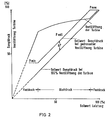
- the steam pressure changes with a delay in accordance with the storage capacity of the steam generator, the opening of the turbine valve and the time behavior of the steam generator. So that there is no control difference for a steam pressure regulator 6 due to a change in the basic setpoint for the block output even in the sliding pressure range (see FIG. 2), the setpoint for the steam pressure must also be delayed in accordance with the actual value.
- the power of the steam generator for loading or unloading the memory is thus overridden in terms of time and amount so that there is no difference between the delayed setpoint "power" and the electrical power.
- the opening of the turbine valve is changed only in the event of a control difference “steam pressure” via the output controller, so that the steam pressure adjusts to the predetermined characteristic curve.
- the memory of the steam generator is not used in the event of schedule changes in performance. This means a gentle driving style for the steam generator.
- the output signal of the integrator INT1 does not change when the setpoint of the block power changes, since then the two signals "basic setpoint / block power" and the product of the output signals of the divider DIU1 and the integrator INT change change to the same extent so that the difference signal at the output of the subtractor SUB7 and thus the input signal of the integrator INT1 remains zero.
- the basic setpoint of the block power is changed, a signal is generated at the input of the integrator INT1, which signal corresponds to the difference between the steam generated and the steam output which is caused by the time behavior of the steam accumulator. This signal is switched to the basic setpoint for steam generation and corresponds to the steam required for charging or discharging the storage tank.
- a delay element VZ3 is connected to the integrator INT1, with which the delay in the change in steam pressure due to the time behavior of the steam generator is taken into account for the setpoint value of the steam pressure.
- a signal is thus generated at its output which, when the basic setpoint for the block power changes, accordingly the valve opening of the turbine, the storage capacity of the steam generator and the time behavior of the steam generator is delayed. This signal can be used as a pressure setpoint for the steam pressure regulator 6.
- the steam pressure regulator 6 is used primarily to correct heating faults. In the event of a heating fault, the steam pressure changes, and the steam pressure regulator should be used to change the setpoint for the steam generator so that the steam output generated remains constant.
- a subtractor SUB8 forms the control deviation of the vapor pressure from the setpoint value for the vapor pressure supplied by the delay element VZ3 and the vapor pressure multiplied in a multiplier M3 by a constant supplied by a constant generator KG1.
- the basic setpoint value for the block power delayed in a delay element VZ2 is divided in a divider DIV2 by the output signal of the delay element VZ3, so that its output signal corresponds to the opening of the turbine valve.
- This is multiplied in a multiplier M2 by the output signal of the subtractor SUB8, which is the control deviation of the steam pressure, and thus generates a signal which corresponds to the missing or excessive steam output.
- This signal is applied to the setpoint for the steam generator in an adder ADD8. So that the valve opening of the turbine remains constant in the event of a heating fault, the output signal of the multiplier M2 corresponding to the control difference "steam flow" is subtracted from the nominal value for the electrical power in a subtractor SUB3. In the event of a heating fault, the valve opening of the turbine is not adjusted and the memory in the steam generator is not additionally used.
- the steam pressure regulator can be set very stably according to a controlled system with 100 ° compensation.
- this signal is fed into the input of a steam generator model, which consists of a delay element VZ4, the timing of which is the same as that of the steam generator, and an integrator INT2, whose timing is equal to the storage time constant of the steam generator.
- the output signal of the delay element VZ4 corresponds to the changed steam generation due to the changed steam generator setpoint. Since the vapor pressure z. B. must be rebuilt in the event of a negative heating fault, the steam delivery of the steam generator is delayed by the charge of the steam accumulator.
- the output signal of the integrator INT2 corresponds to the changed steam delivery of the steam generator, since the storage capacity of the steam generator is simulated in this integrator.
- a differential can also be applied by means of a differentiating element DF2 and an adder ADD5.
- the lead is derived from the control difference.
- the lead is derived from the control difference "steam flow” and the output signal of the steam generator model VZ4, INT2. This has the advantage that the output variable of the lead decreases to zero when the control difference "steam flow” is reduced without changing the polarity.
- the signal at the input of the integrator INT1 remains zero in the fixed pressure range. So that the input and output signal of the delay element VZ3 is constant, namely p min or p max .
- the setpoint for the electrical power changes with a constant opening of the turbine valve without a time lag with the generation of the electrical power. This means that without applying the control difference "steam flow" occurring at the output of the multiplier M2, the control difference at the input of the power controller would remain zero.
- ⁇ f is supplied to a unit 1 which serves to limit the frequency deviation signal when the upper or the lower limit power is reached.
- unit 1 is supplied with the basic setpoint of the block power and compared in subtractors SUB1, SUB2 with the lower limit power p min or the upper limit power p max , which are set in adjusters ST2, ST3.
- the difference signals are fed to a minimum selection MIN1 or a maximum selection MAX2.
- a maximum selection MAX1 is connected to the former, and a minimum selection MIN2 is connected via an inverter IV1 and is further connected to the maximum selection MAX1, MAX2.
- the output signal of the maximum selection MAX2 is the allowance for a power increase in the event of a frequency drop and the output signal of the minimum selection MIN1 is the allowance for a power decrease in the event of a frequency increase. If the frequency control in the lower power range should not be effective even in the event of a frequency drop, the output signal of the minimum selection MIN1 is given with the opposite sign via the inverter IV1 in the minimum selection MIN2.
- the frequency deviation, if any, limited by the minimum selection MIN2 signal k • ⁇ f is added by an adder ADD1 to the setpoint for the electrical power and by an adder ADD2 to the basic setpoint for the steam generator.
- the adder ADD2 is arranged so that the frequency signal has the same effect as a change in the basic setpoint value of the block power, ie the power of the steam generator is overridden in order to load or discharge the memory in the steam generator.
- the electrical power follows exactly a setpoint change due to a frequency change if the control difference on the steam pressure controller is kept at zero. Since the opening of the turbine valve is immediately adjusted in the event of a frequency change via the power regulator, a "steam pressure dent" arises from the removal of steam from the storage of the steam generator. If a signal corresponding to this "steam pressure dent" is added to the control difference "steam pressure", a frequency deviation does not change the control difference at the steam pressure controller.
- the signal corresponding to the "vapor pressure dent" is generated in a unit 2, which is described in more detail below.
- the steam pressure changes according to the storage time constant of the steam generator if there is a difference between the steam generated and the steam drawn.
- the size of the frequency signal added to the setpoint value of the electric power corresponds to that of the steam removed.
- the time behavior of the steam generator is simulated in a delay element VZ5. Since the setpoint change of the steam generator is switched to the input of the delay element due to a frequency deviation of the same size, its output signal corresponds to the steam generated, which is available for generating the electrical power.
- a subtractor SUB5 therefore forms a signal which corresponds to the difference between the generated and removed steam.
- This signal is fed into an integrator INT3, the time constant of which is equal to the storage time constant of the steam generator. Its output signal is therefore the same size as the vapor pressure deviation due to the change in power due to the change in frequency.
- This integrator signal is added to the control difference "vapor pressure" formed by the subtractor SUB8, so that in the vapor pressure regulator 6 the change in the vapor pressure which occurs due to the frequency change is compensated.
- the input signal of the integrator INT3 In the event of a frequency drop, the input signal of the integrator INT3, and thus also its output signal, becomes negative, since more steam is initially extracted than is generated.
- the output signal of the integrator remains when the generated steam is the same size as the extracted steam. In order for the output signal to go back to zero, more steam must be generated than is withdrawn. This is achieved in that the input signal of the delay element VZ5 by applying the signal corresponding to the pressure dent, e.g. B. is increased by a factor of 0.2 to 0.3.
- the frequency increases, more steam is initially generated than is withdrawn. Applying the signal corresponding to the pressure bulge then causes less steam to be generated than is extracted.
- a delay of the frequency signal is additionally generated by means of a differentiating element DF1 and added to the basic setpoint for the steam generator with an adder ADD7, so that the steam generation is increased as early as possible or is reduced in the event of a frequency increase.
- the lead is also given to the input of the delay element VZ5.
- the shape of the pressure dent which is caused by a frequency change, is determined by the size of the connection.
- the opening of the turbine valve is temporarily set to 100% via the controller for the electrical power.
- a positive control difference Xd arises at the power controller. Since the steam withdrawn decreases by this amount, the positive control difference of the electrical power is given into the input of the integrator INT3 at 100 ° o valve opening via a maximum selection MAX4, so that the pressure bulge is simulated correctly even when the power control is not effective.
- an adjuster ST7 is provided, which emits a signal corresponding to the valve opening 100%, which is subtracted from the actual valve opening by a subtractor SUB6.
- the control difference Xd of the electrical power is applied to this difference.
- the maximum selection MAX4 only gives the part of the signal thus formed to the integrator INT3 that exceeds the value zero.
- a signal is applied to the setpoint for the steam generator via the adder ADD6 to the basic setpoint for the steam generation, which leads to the steam generator being overridden for charging or discharging the memory.
- the steam generation for charging or discharging the memory is not overridden in the event of schedule changes in power, so that the generation of the electrical power is additionally delayed in the sliding pressure range.
- FIG. 3 only those elements are provided with reference numerals that are necessary for the description of the changes compared to the exemplary embodiment according to FIG. 1. The elements that have the same functions in the two exemplary embodiments are provided with the same reference symbols.
- the control difference of the electrical power remains zero, the input value of the electrical power in front of the delay element VZ1 is subtracted from the input signal of an integrator INT5, which corresponds to the integrator INT1 according to FIG . that is, a signal corresponding to the amount of storage steam is subtracted.
- the steam generation is not overridden in this case, so that the steam generator is driven particularly gently.
- the setpoint value of the electrical power must be changed in the event of a frequency deviation, as in the exemplary embodiment according to FIG. 1.
- a lead consisting of an integrator INT4 and a multiplier M5 is used for this.
- the time constant of the integrator INT4 is the same again the storage time constant of the steam generator.
- a limiting device 7 ensures that in the event of a frequency change, the lead to the setpoint of the steam generator is effective only in the sliding pressure range.
- a subtractor SUB9 is provided, in which the input signals of the integration elements INT4, INT5 are compensated.
- the input signal of the integrator INT4 reaches an adder ADD9, in which it is added to the basic setpoint for the steam generator.
- Figure 4 illustrates an embodiment in which the memory of the steam generator is used even in the event of schedule changes in performance.
- the basic setpoint for the power is given to the turbine valve as the setpoint for the electrical power without delay.
- the setpoint for the steam generation and the pressure setpoint are formed as in the exemplary embodiment according to FIG. 1. Since the memory of the steam generator is also used in the event of schedule changes in performance, this mode of operation must be taken into account for the formation of a signal which corresponds to the "pressure dent".
- This signal is generated with an arrangement which is already contained in the exemplary embodiment according to FIG. 1 and is designated by 2.
- the frequency deviation signal k - ⁇ f but also the basic setpoint for the block power is supplied to this arrangement.
- the steam pressure deviation can become impermissibly large due to the use of the accumulator in the case of a power control using the turbine valve.
- the output is only regulated within a specified limit in accordance with the block setpoint (controlled system without compensation).
- a dead band TB is provided for setting the limits. If the size of the "pressure dent" exceeds set limit, the power control is changed. The signal then let through by the dead band is multiplied by the setpoint for the valve opening in a multiplier M6.
- This signal which corresponds to the "power bulge” is added to the setpoint value of the block power in an adder ADD10 and also to the setpoint value of the electrical power in an adder ADD11. It is e.g. B. at a power increase, the output signal of the integrator INT3 negative, so that the signal corresponding to the steam removed and the setpoint for the electrical power become smaller, thus reducing the speed of the power change. Since the input signal of the integrator INT3 corresponds to the difference between the steam withdrawn and the steam generated, the pressure bulge is also correctly simulated in this case.
- the opening of the turbine valve via the power controller is exactly proportional to the setpoint value in the event of a schedule power change by connecting the “power dent” to the setpoint value of the electrical power the block power is adjusted. Since the valve opening is adjusted like a control without overshoot, the control of the steam pressure and the electrical power is very stable.
- this concept can be used to manually change the power by adjusting the opening of the turbine valve.
- the calculated “setpoint steam” for the setpoint formation of the steam generator only has to be applied and the limits of the dead band set to zero.
- the control difference “steam flow rate” which arises due to a disturbance in steam generation is subtracted from the setpoint value of the electrical power so that the valve opening of the turbine remains constant. There is then no control difference at the power regulator of the turbine, since the electrical power has changed by the same amount as the setpoint for the electrical power due to the pressure deviation. Since the valve opening of the turbine is kept constant regardless of the electrical power, it is a controlled system with 100 ° compensation. If, on the other hand, the electrical power is kept constant by adjusting the turbine valve via the power regulator of the turbine, the steam removed is greater than the steam generated. The vapor pressure therefore drops and only rises again when the generated steam becomes larger than the extracted steam. Since the steam extraction is controlled independently of the steam pressure, the controlled system has no compensation.
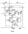
- FIG. 5 shows the functional diagram of a steam pressure regulator with which this requirement is met.
- the control difference "vapor pressure" at the output of the subtractor SUB8 is an amplitude-dependent attenuator, e.g. B. a so-called dead band TD, whose dead zone, in which the damping is 100 S, can be set with an actuator ST8.
- the output signal of the dead band TD is multiplied by the multiplexer M2 by the setpoint for the valve opening of the turbine and the signal thus obtained is subtracted from the setpoint for the electrical power in the subtractor SUB3 and added to the setpoint for the steam generator in the adder ADD8.
- the two inputs of a subtractor SUB10 are connected to the output and the input of the dead band TD, to which a differentiator DF4 and a multiplier M7 are connected.
- the time constant of the differentiator DF4 is set to that of the steam accumulator. Its output signal is added to the signal of the multiplier M2 in an adder ADD13.
- the output signal of the subtractor SUB10 is multiplier M7 with a constant, e.g. B. 0.2 ... 0.3, multiplied and added to the setpoint for the steam generator via adders ADD12 and ADD8.
- the dead zone of the dead band TD is set to zero.
- the input and output signals of the dead band are the same, and the output signal of the subtractor SUB10 is zero.
- the differentiator DF4 and the multiplier M7 thus have no effect on the control.
- the steam pressure regulator according to FIG. 5 then works like that described in FIG. 1.
- the dead zone of the dead band TD is set so large that the largest expected dif Reference signal at the output of the subtractor SUBB is not passed and thus the compensation signal to the subtractor SUB3 is zero.
- the steam pressure remains constant. If there is a difference, the rate of change in pressure caused by this only depends on the storage time constant of the steam generator. Accordingly, the control difference "steam flow” is simulated via the differentiator DF4 with the control difference "steam pressure” as an input signal.
- the control difference "steam flow rate” determined in this way is applied to the steam pressure regulator via the adders ADD13, ADD4, ADD12 and ADD8.
- the electrical output can only be kept constant as long as the valve opening of the turbine remains in the control range. If the valve is fully opened in the event of a major disturbance in steam generation, the degree of compensation of the controlled system changes from 0 to 100 ä. Without taking this limit case into account, the steam pressure regulator would work more slowly than the controlled system allows, but the control would remain stable. However, since the change in the degree of compensation at 100% valve opening is already taken into account when the pressure setpoint is controlled with the connection of the “pressure bump” described with reference to FIG. 1, the steam pressure regulator also works optimally in this limit case.
- the degree of compensation is to be changed depending on the size of the disturbance, that is to say the control difference "vapor pressure”
- a amplitude-dependent attenuator are used, the attenuation of which is large for small amplitudes and small for large amplitudes.
- the above-mentioned dead band is used as the amplitude-dependent attenuator, the electrical power is quickly corrected within a certain bandwidth by adjusting the valve opening and the valve opening of the turbine is kept constant outside this bandwidth.
- the control difference "vapor pressure” is greater than the dead zone set on the dead band, the difference between the input and output signal of the dead band and thus also the output of the subtractor SUB10 remains constant.
Abstract
Description
Die Erfindung betrifft ein Verfahren zum Regeln eines eine Turbine und einen Dampferzeuger enthaltenden Kraftwerkblockes, bei dem der Grundsollwert für die Blockleistung dem Dampferzeuger als Grundsollwert für die Dampferzeugung und der Turbinenregelung als Grundsollwert für die elektrische Leistung zugeführt ist.The invention relates to a method for controlling a power plant block containing a turbine and a steam generator, in which the basic setpoint for the block power is supplied to the steam generator as the basic setpoint for the steam generation and the turbine control as the basic setpoint for the electrical power.
In der Zeitschrift "Regelungstechnische Praxis und Prozeßrechentechnik", 1974, Seiten 9 bis 16 ist ein Verfahren beschrieben, das als gesteuerter bzw. modifizierter Gleitdruckbetrieb bezeichnet wird und bei dem der Regelkreis für den Dampferzeuger mit dem Dampfdruck als Regelgröße und der für die Turbine mit der Leistung als Regelgröße getrennt wird. Durch Verändern der Öffnung des Turbineneinlaßventils wird die Leistung auf den Sollwert eingeregelt. Der Dampferzeuger soll die Lastschwankungen ausregeln, die Öffnung des Turbineneinlaßventils soll in einem weiten Leistungsbereich konstant bleiben. In der DE-OS 24 23 082 ist ferner angegeben, die Frequenz der erzeugten Wechselspannung mit einer Sollfrequenz zu vergleichen und das der Abweichung entsprechende Signal dem Sollwert für die Leistung bzw. dem Steuersignal für den Stellantrieb des Turbinenöffnungsventils aufzuschalten. Bei derartigen Verfahren handelt es sich um Regelstrecken ohne Ausgleich, so daß eine stabile Regelung der Dampferzeugung wegen der Trägheit des Dampferzeugers nur schwierig erreicht werden kann. Ist z. B. bei einer Kohlefeuerung die Verzugszeit relativ groß, so muß der Dampfdruck, der bereits als Regelgröße für den Dampferzeuger verwendet wird, zusätzlich zur Stabilisierung proportional auf die Regelung der Turbine geschaltet werden. Dampfdruck und Leistungsregelung beeinflussen sich gegenseitig, so daß eine Mitkopplung zwischen der Dampferzeuger- und der Leistungsregelung mit der Turbine vorhanden ist. Ein weiterer Nachteil einer solchen Regelung ist, daß auch bei gezielten Laständerungen und bei Beheizungsstörungen der Dampfspeicher über die Leistungsregelung mit der Ventilöffnung der Turbine als Stellglied in Anspruch genommen wird, so daß nicht nur die Dampfdruckregelung mit dem Dampferzeuger erschwert wird, sondern der Dampferzeuger nicht schonend gefahren wird.In the magazine "Control engineering practice and process computing", 1974, pages 9 to 16, a method is described, which is referred to as a controlled or modified sliding pressure operation and in which the control circuit for the steam generator with the steam pressure as the control variable and that for the turbine with the Performance is separated as a control variable. By changing the opening of the turbine inlet valve, the power is adjusted to the setpoint. The steam generator should regulate the load fluctuations, the opening of the turbine inlet valve should remain constant over a wide performance range. DE-OS 24 23 082 also specifies to compare the frequency of the alternating voltage generated with a nominal frequency and to apply the signal corresponding to the deviation to the nominal value for the power or the control signal for the actuator of the turbine opening valve. Such methods are controlled systems without compensation, so that stable control of the steam generation can only be achieved with difficulty because of the inertia of the steam generator. Is z. B. in the case of coal firing the delay time is relatively long, the steam pressure, which is already used as a control variable for the steam generator, must be switched proportionally to the regulation of the turbine in addition to stabilization. Steam pressure and power control mutually influence each other, so that there is positive feedback between the steam generator and power control with the turbine. Another disadvantage of such a regulation is that even with targeted load changes and in the event of heating faults, the steam accumulator is used as an actuator via the capacity control with the valve opening of the turbine is, so that not only the steam pressure control with the steam generator is difficult, but the steam generator is not driven gently.
Aus der DE-OS 29 03 658 ist ein Verfahren bekannt, bei dem keine Mitkopplung zwischen der Dampferzeugerregelung und der Steuerung der Öffnung des Turbinenventils besteht und die Dampferzeugerregelung daher sehr stabil eingestellt werden kann. Der Speicherdampf wird nur im Falle von plötzlichen Abweichungen der Frequenz von der Sollfrequenz in Anspruch genommen, wodurch sich eine schonende Fahrweise für den Dampferzeuger ergibt. Damit einem Frequenzabfall entgegengewirkt werden kann, ist das Ventil im Gleitdruckbetrieb nicht voll, sondern nur teilweise geöffnet. Im Falle eines Frequenzanstieges wird die Ventilöffnung verkleinert. Das bekannte Verfahren soll somit in einem weiten Lastbereich, dem Gleitdruckbereich, in der Weise ablaufen, daß bei Änderungen des Sollwertes für die abzugebende Leistung, also bei gezielten Laständerungen oder bei Schwankungen der abgegebenen Leistung, z. B. infolge von Beheizungsstörungen, die Öffnung des Turbinenventils konstant bleibt und nur der Dampferzeuger nachgeregelt wird. Nur bei plötzlichen Änderungen der Netzfrequenz wird in dieser Betriebsart die Turbinenventilöffnung geändert und damit der Dampfspeicher in Anspruch genommen. Im unteren und oberen Lastbereich wird im sogenannten Festdruckbetrieb gearbeitet, d. h., zur fahrplanmäßigen Leistungsänderung wird bei konstantem Dampfdruck die Öffnung des Turbineneinlaßventils verändert. Damit der Dampfspeicher nicht in Anspruch genommen wird, erfolgt die Verstellung des Sollwertes für die Ventilöffnung über ein Verzögerungsglied, mit welchem die Verzugszeit-des Dampferzeugers nachgebildet wird. Da durch diese Maßnahme die Ventilöffnung erst mit der veränderten Dampferzeugung verstellt wird, bleibt der Dampfdruck bei einer Laständerung konstant. Bei diesem bekannten Verfahren wird das Speicherverhalten des Dampferzeugers nur unvollständig berücksichtigt. Auch werden keine Maßnahmen vorgeschlagen, mit denen im Falle einer Beheizungsstörung die Ventilöffnung nicht verändert wird. Für die Ausregelung von Frequenzabweichungen ist eine exakte Nachbildung des lastabhängigen Zeitverhaltens des Dampferzeugers erforderlich.From DE-OS 29 03 658 a method is known in which there is no positive feedback between the steam generator control and the control of the opening of the turbine valve and the steam generator control can therefore be set very stably. The storage steam is only used in the event of sudden deviations in frequency from the target frequency, which results in a gentle driving style for the steam generator. In order to counteract a drop in frequency, the valve is not full in sliding pressure mode, but only partially open. In the event of a frequency increase, the valve opening is reduced. The known method should thus run in a wide load range, the sliding pressure range, in such a way that when there are changes in the setpoint for the power to be output, that is to say with targeted load changes or in the event of fluctuations in the power output, for. B. due to heating faults, the opening of the turbine valve remains constant and only the steam generator is readjusted. Only in the event of sudden changes in the mains frequency is the turbine valve opening changed in this operating mode and thus the steam accumulator is used. In the lower and upper load range, so-called fixed pressure operation is used, ie the opening of the turbine inlet valve is changed with a constant steam pressure in order to change the power. So that the steam accumulator is not used, the setpoint for the valve opening is adjusted via a delay element with which the delay time of the steam generator is simulated. Since this measure only adjusts the valve opening when the steam generation changes, the steam pressure remains constant when the load changes. In this known method, the storage behavior of the steam generator is only considered incompletely. Also, no measures are proposed with which the valve opening is not changed in the event of a heating fault. An exact replication of the load-dependent time behavior of the steam generator is required for the regulation of frequency deviations.
Der vorliegenden Erfindung liegt die Aufgabe zugrunde, ein Verfahren der eingangs genannten Art zu schaffen, bei dem die dynamischen Vorgänge bei Leistungsänderungen stärker berücksichtigt werden als bei den bekannten Verfahren und dadurch die Steuer- und Regelvorgänge besser getrennt sind und bei dem ferner die Inbetriebnahme vereinfacht ist.The present invention has for its object to provide a method of the type mentioned, in which the dynamic processes in power changes are taken into account more than in the known methods and thereby the control and regulation processes are better separated and in which the commissioning is also simplified .
Erfindungsgemäß wird diese Aufgabe mit den im kennzeichnenden Teil des Anspruchs 1 genannten Maßnahmen gelöst.According to the invention, this object is achieved with the measures mentioned in the characterizing part of
Damit im Falle einer veränderten Einstellung des Sollwertes für die Leistung sich der Dampfdruck möglichst schnell auf die geforderte Leistung einstellt, wird der Dampferzeuger vorteilhaft kurzzeitig übersteuert, damit der Speicher des Dampferzeugers auf den neuen Dampfdruck auf- bzw. entladen wird. Hierzu wird vorzugsweise ein erster der Öffnung des Turbineneinlaßventils entsprechender Wert gebildet und dem einen Eingang eines Multiplizierers zugeführt, dessen Ausgangssignal vom Grundsollwert für die Blockleistung subtrahiert wird. Der Differenzwert wird dem Grundsollwert für den Dampferzeuger aufgeschaltet und dem Eingang eines das Speicherverhalten des Dampferzeugers nachbildenden Integrators zugeführt, an dessen Ausgang der zweite Eingang des Multiplizierers angeschlossen ist.So that in the event of a changed setting of the setpoint for the power, the steam pressure adjusts itself to the required power as quickly as possible, the steam generator is advantageously briefly overridden, so that the steam generator's memory is charged or discharged to the new steam pressure. For this purpose, a first value corresponding to the opening of the turbine inlet valve is preferably formed and fed to the one input of a multiplier, the output signal of which is subtracted from the basic setpoint for the block power. The difference value is applied to the basic setpoint for the steam generator and fed to the input of an integrator emulating the storage behavior of the steam generator, to the output of which the second input of the multiplier is connected.
Soll jedoch der Dampferzeuger besonders schonend gefahren und aus diesem Grunde nicht übersteuert werden und soll auch der Dampfspeicher im Falle einer Leistungsänderung nach Fahrplan nicht in Anspruch genommen werden, wird der Differenzwert vom Sollwert für die elektrische Leistung subtrahiert.However, if the steam generator is to be operated with particular care and should not be overridden for this reason, and if the steam accumulator should not be used in the event of a change in output according to the schedule, the difference value is subtracted from the setpoint for the electrical output.
Zur Frequenzstützung wird vorteilhaft ein der Frequenzabweichung vom Sollwert entsprechendes Signal dem Sollwert für die elektrische Leistung, also zur Steuerung des Turbinenventils, und dem Sollwert für den Dampferzeuger zugeführt. Zur Auf- bzw. Entladung des Speichers des Dampferzeugers kann das der Frequenzabweichung entsprechende Signal direkt sowie über ein der Verzugszeit des Dampferzeugers entsprechendes Verzögerungsglied auf eine Subtraktionsstufe geführt sein, deren Ausgangssignal dem Sollwert für den Dampferzeuger aufgeschaltet ist.For frequency support, a signal corresponding to the frequency deviation from the desired value is advantageously fed to the desired value for the electrical power, that is to say to control the turbine valve, and to the desired value for the steam generator. To charge or discharge the memory of the steam generator, the signal corresponding to the frequency deviation can be used directly and via a delay time of the steamer The corresponding delay element can be guided to a subtraction stage, the output signal of which is applied to the setpoint for the steam generator.
Weitere Ausgestaltungen und Vorteile der Erfindung werden im folgenden anhand der Zeichnungen näher beschrieben und erläutert.Further refinements and advantages of the invention are described and explained in more detail below with reference to the drawings.
Es zeigen
Figur 1 den Funktionsplan eines ersten Ausführungsbeispiels der Erfindung, bei dem im Falle einer fahrplanmäßigen Laständerung ohne Inanspruchnahme des Dampfspeichers der Dampferzeuger rasch auf die neue Leistung eingestellt wird,Figur 2 Diagramme zur Verdeutlichung der Funktion des Ausführungsbeispiels nachFigur 1,Figur 3 den Funktionsplan eines Ausführungsbeispiels, bei dem im Falle einer fahrplanmäßigen Leistungsänderung der Dampferzeuger ohne Übersteuerung auf die neue Leistung eingestellt wird,Figur 4 den Funktionsplan eines Ausführungsbeispiels, bei dem im Falle einer fahrplanmäßigen Leistungsänderung der Dampfspeicher in Anspruch genommen wird, undFigur 5 den Funktionsplan des Ausführungsbeispiels eines Dampfdruckreglers mit veränderlichem Ausgleichsgrad der Regelstrecke.
- 1 shows the functional diagram of a first exemplary embodiment of the invention, in which the steam generator is quickly set to the new output in the event of a schedule load change without using the steam accumulator,
- FIG. 2 diagrams to illustrate the function of the exemplary embodiment according to FIG. 1,
- FIG. 3 shows the functional diagram of an exemplary embodiment in which the steam generator is set to the new output without overriding in the event of a schedule change in output,
- FIG. 4 shows the functional diagram of an exemplary embodiment in which the steam accumulator is used in the event of a schedule change in output, and
- Figure 5 shows the functional diagram of the embodiment of a steam pressure regulator with variable degree of compensation of the controlled system.
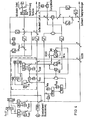
Bei dem in Figur 1 veranschaulichten Ausführungsbeispiel wird, wie bekannt, die elektrische Leistung mit dem Turbineneinlaßventil und der Dampfdruck mit dem Dampferzeuger geregelt. Der Grundsollwert für die Blockleistung wird entsprechend eines Fahrplanes mit einem Einsteller ST1 eingestellt und über eine nachgeschaltete Sollwertführung SWF an die Blockregelung weitergegeben. Dieser Grundsollwert für die Blockleistung wird unverzögert als Sollwert für die Dampferzeugung über eine Leitung SWD und über ein Verzögerungsglied VZ1, dessen Zeitverhalten gleich dem des Dampferzeugers ist, als Sollwert für die elektrische Leistung über eine Leitung SWL weitergegeben.In the exemplary embodiment illustrated in FIG. 1, as is known, the electrical power is regulated using the turbine inlet valve and the steam pressure using the steam generator. The basic setpoint for the block output is set according to a schedule with an adjuster ST1 and passed on to the block control via a downstream setpoint control SWF. This basic setpoint for the block power is passed on without delay as a setpoint for the steam generation via a line SWD and via a delay element VZ1, the timing of which is the same as that of the steam generator, as a setpoint for the electrical power via a line SWL.
In dem Verzögerungsglied VZ1 ist die Verzugs- und Anlaufzeit des Dampferzeugers nachgebildet. Diese Übergangsfunktion wird ermittelt, indem bei mit der Turbine konstant geregeltem Dampfdruck der Sollwert für den Dampferzeuger sprunghaft verstellt und der zeitliche Verlauf der elektrischen Leistung aufgenommen wird. Da das Zeitverhalten des Dampferzeugers von der Leistung abhängig ist, muß die Übergangsfunktion bei mehreren, z. B. drei verschiedenen, Lastpunkten aufgenommen werden. Nach diesen Werten wird das Zeitverhalten der mit VZ1, VZ2 ... bezeichneten Verzögerungsglieder vom Sollwert für die Blockleistung gesteuert.The delay and start-up time of the steam generator is simulated in the delay element VZ1. This transition function is determined by suddenly changing the setpoint for the steam generator and the temporal value when the steam pressure is constantly controlled by the turbine Course of electrical power is recorded. Since the time behavior of the steam generator depends on the power, the transition function must be with several, for. B. three different, load points are included. According to these values, the time behavior of the delay elements designated VZ1, VZ2 ... is controlled by the setpoint for the block power.
Eine gestrichelt umrandete Einheit 4 dient zur Erzeugung eines Signals, das in etwa der Ventilöffnung entspricht. Im Gleitdruckbereich ist innerhalb von Grenzsollwerten pmin und p , die mit Einstellern ST4, ST5 eingestellt werden, der Drucksollwert leistungsabhängig. Bei konstanter Drosselreserve im gesamten Gleitdruckbereich wird für die Bildung des Drucksollwertes in einem Addierer ADD3 zum Leistungssollwert ein konstanter Wert Δp, der mit einem Einsteller ST6 eingestellt wird, addiert. Dem Addierer ADD3 und dem Einsteller ST4 ist eine Minimalauswahl MIN3 nachgeschaltet, an die der eine Eingang einer Maximalauswahl MAX3 angeschlossen ist, dem ferner der Grenzsollwert pmin zugeführt ist. Am Ausgang der Maximalauswahl MAX3 entsteht ein Grundsollwert für den Dampfdruck. Seine Abhängigkeit vom Sollwert für die Blockleistung ist im Diagramm psoll der Figur 2 dargestellt. Durch die Addition der Konstanten Ap zum Leistungssollwert stellt sich über die noch zu beschreibende Leistungsregelung entsprechend der vorgegebenen Kennlinie "Dampfdruck in Abhängigkeit von der Leistung" die Ventilöffnung der Turbine lastabhängig ein, wie am Diagramm "Ventilöffnung" in Figur 2 ersichtlich ist. Das der Ventilöffnung in etwa entsprechende Signal wird dadurch gebildet, daß ein Dividierer DIV1 den Grundsollwert für die Blockleistung durch den am Ausgang der Maximalauswahl MAX3 auftretenden Grundsollwert für den Dampfdruck dividiert.A
Bei einer Änderung des Grundsollwertes für die Blockleistung ändert sich der Dampfdruck verzögert entsprechend der Speicherfähigkeit des Dampferzeugers, der Öffnung des Turbinenventils und dem Zeitverhalten des Dampferzeugers. Damit aufgrund einer Änderung des Grundsollwertes für die Blockleistung auch im Gleitdruckbereich (siehe Figur 2) für einen Dampfdruckregler 6 keine Regeldifferenz entsteht, muß auch der Sollwert für den Dampfdruck entsprechend dem Istwert verzögert werden. Die Verzögerung der Dampfdruckänderung infolge der Ladung bzw. Entladung des Speichers im Dampferzeuger wird mit einer Anordnung 5 berücksichtigt, die aus einem Multiplizierer M1, einem Subtrahierer SUB7 und einem Integrator INT1 besteht, dessen Zeitkonstante gleich der Speicherzeitkonstante des Dampferzeugers ist. Da diese Schaltung entsprechend der Gleichung "Ventilöffnung x Druck = Leistung" aufgebaut ist, hat im statischen Zustand der Ausgang des Integrators den gleichen Wert wie der Drucksollwert am Ausgang der Maximalauswahl MAX3.If the basic setpoint for the block output changes, the steam pressure changes with a delay in accordance with the storage capacity of the steam generator, the opening of the turbine valve and the time behavior of the steam generator. So that there is no control difference for a
Im Gleitdruckbetrieb wird somit die Leistung des Dampferzeugern für die Beladung bzw. Entladung des Speichers zeitlich und dem Betrage nach so übersteuert, daß zwischen dem verzögerten Sollwert "Leistung" und der elektrischen Leistung keine Differenz entsteht. Während einer Leistungsänderung wird lediglich bei einer Regeldifferenz "Dampfdruck" über den Leistungsregler die Öffnung des Turbinenventils verändert, so daß der Dampfdruck sich auf die vorgegebene Kennlinie einstellt. Bei fahrplanmäßigen Leistungsänderungen wird der Speicher des Dampferzeugers nicht in Anspruch genommen. Dies bedeutet für den Dampferzeuger eine schonende Fahrweise.In sliding pressure mode, the power of the steam generator for loading or unloading the memory is thus overridden in terms of time and amount so that there is no difference between the delayed setpoint "power" and the electrical power. During a change in output, the opening of the turbine valve is changed only in the event of a control difference “steam pressure” via the output controller, so that the steam pressure adjusts to the predetermined characteristic curve. The memory of the steam generator is not used in the event of schedule changes in performance. This means a gentle driving style for the steam generator.
Im Festdruckbereich, wenn der Drucksollwert pmin oder pmax ist, ändert sich bei einer Sollwertänderung der Blockleistung das Ausgangssignal des Integrators INT1 nicht, da dann die beiden Signale "Grundsollwert/Blockleistung" und das Produkt der Ausgangssignale des Dividierers DIU1 und des Integrators INT sich im gleichen Maße ändern, so daß das Differenzsignal am Ausgang des Subtrahierers SUB7 und damit das Eingangssignal des Integrators INT1 Null bleibt. Bei einer Änderung des Grundsollwertes der Blockleistung entsteht am Eingang des Integrators INT1 ein Signal, welches der durch das Zeitverhalten des Dampfspeichers verursachten Differenz zwischen erzeugtem und abgegebenem Dampf entspricht. Dieses Signal wird auf den Grundsollwert für die Dampferzeugung geschaltet und entspricht dem für die Ladung bzw. Entladung des Speichers erforderlichen Dampf.In the fixed pressure range, when the pressure setpoint is p min or p max , the output signal of the integrator INT1 does not change when the setpoint of the block power changes, since then the two signals "basic setpoint / block power" and the product of the output signals of the divider DIU1 and the integrator INT change change to the same extent so that the difference signal at the output of the subtractor SUB7 and thus the input signal of the integrator INT1 remains zero. When the basic setpoint of the block power is changed, a signal is generated at the input of the integrator INT1, which signal corresponds to the difference between the steam generated and the steam output which is caused by the time behavior of the steam accumulator. This signal is switched to the basic setpoint for steam generation and corresponds to the steam required for charging or discharging the storage tank.
An den Integrator INT1 ist ein Verzögerungsglied VZ3 angeschlossen, mit dem die Verzögerung der Dampfdruckänderung infolge des Zeitverhaltens des Dampferzeugers für den Sollwert des Dampfdruckes berücksichtigt wird. An seinem Ausgang entsteht somit ein Signal, das bei einer Änderung des Grundsollwertes für die Blockleistung entsprechend der Ventilöffnung der Turbine, der Speicherfähigkeit des Dampferzeugers und dem Zeitverhalten des Dampferzeugers verzögert ist. Dieses Signal kann als Drucksollwert für den Dampfdruckregler 6 verwendet werden.A delay element VZ3 is connected to the integrator INT1, with which the delay in the change in steam pressure due to the time behavior of the steam generator is taken into account for the setpoint value of the steam pressure. A signal is thus generated at its output which, when the basic setpoint for the block power changes, accordingly the valve opening of the turbine, the storage capacity of the steam generator and the time behavior of the steam generator is delayed. This signal can be used as a pressure setpoint for the
Der Dampfdruckregler 6 dient vor allem zum Ausregeln von Beheizungsstörungen. Im Falle einer Beheizungsstörung ändert sich nämlich der Dampfdruck und über den Dampfdruckregler soll der Sollwert für den Dampferzeuger so geändert werden, daß die erzeugte Dampfleistung konstant bleibt. Aus dem vom Verzögerungsglied VZ3 gelieferten Sollwert für den Dampfdruck und dem in einem Multiplizierer M3 mit einer von einem Konstantengeber KG1 gelieferten Konstanten multiplizierten Dampfdruck bildet ein Subtrahierer SUB8 die Regelabweichung des Dampfdrucks. Der in einem Verzögerungsglied VZ2 verzögerte Grundsollwert für die Blockleistung wird in einem Dividierer DIV2 durch das Ausgangssignal des Verzögerungsgliedes VZ3 dividiert, so daß dessen Ausgangssignal der Öffnung des Turbinenventils entspricht. Dieser wird in einem Multiplizierer M2 mit dem Ausgangssignal des Subtrahierers SUB8, das ist die Regelabweichung des Dampfdrucks, multipliziert und erzeugt damit ein Signal, das der fehlenden oder zu großen Dampfleistung entspricht. Dieses Signal wird auf den Sollwert für den Dampferzeuger in einem Addierer ADD8 aufgeschaltet. Damit bei einer Beheizungsstörung die Ventilöffnung der Turbine konstant bleibt, wird das der Regeldifferenz "Dampfdurchfluß" entsprechende Ausgangssignal des Multiplizierers M2 vom Sollwert für die elektrische Leistung in einem Subtrahierer SUB3 subtrahiert. Damit wird bei einer Beheizungsstörung die Ventilöffnung der Turbine nicht verstellt und der Speicher im Dampferzeuger nicht zusätzlich in Anspruch genommen. Der Dampfdruckregler kann entsprechend einer Regelstrecke mit 100 °o Ausgleich sehr stabil eingestellt werden.The
Bei einer Beheizungsstörung ist, wenn die Öffnung des Turbinenventils konstant und die Dampfdruckregelung abgeschaltet ist, der zeitliche Verlauf des Dampfdruckes vom Zeitverhalten und der Speicherzeitkonstanten des Dampferzeugers abhängig. Wenn dem Dampfdruckregler das Verhalten der Regelstrecke mitgeteilt wird, ist dieser Regler aufgrund seines Aufbaus bereits optimiert. Bei einer Beheizungsstörung wird die am Ausgang des Multiplizierers M2 auftretende Regeldifferenz "Dampfdurchfluß" (Regeldifferenz "Dampfdruck" x Sollwert "Ventilöffnung") ohne Bewertung, d. h. mit dem Faktor 1, zum Sollwert für die "Dampferzeugung" addiert. Parallel dazu wird dieses Signal in den Eingang eines Dampferzeugermodells gegeben, das aus einem Verzögerungsglied VZ4, dessen Zeitverhalten gleich dem des Dampferzeugers ist, und einem Integrator INT2 besteht, dessen Zeitverhalten gleich der Speicherzeitkonstanten des Dampferzeugers ist. Das Ausgangssignal des Verzögerungsgliedes VZ4 entspricht der veränderten Dampferzeugung aufgrund des veränderten Dampferzeugersollwertes. Da der Dampfdruck z. B. bei einer negativen Beheizungsstörung wieder aufgebaut werden muß, verzögert sich durch die Ladung des Dampfspeichers die Dampfabgabe des Dampferzeugers. Das Ausgangssignal des Integrators INT2 entspricht der veränderten Dampfabgabe des Dampferzeugers, da in diesem Integrator die Speicherfähigkeit des Dampferzeugers nachgebildet ist. Der beschriebene Vorgang am Dampferzeugermodell spielt sich zeitlich und dem Betrage nach im Dampferzeuger in gleicher Weise ab; somit verringert sich die Regeldifferenz "Dampfdurchfluß" um den Betrag, um den das Ausgangssignal des Integrators INT2 steigt. Wenn die Beheizungsstörung ausgeregelt ist, entspricht das Ausgangssignal des Integrators INT2 dem Betrag der bleibenden Beheizungsstörung. Wird die Zeitkonstante des Verzögerungsgliedes VZ4 in Abhängigkeit von der Last entsprechend dem lastabhängigen Zeitverhalten des Dampferzeugers gesteuert, ist der Dampfdruckregler 6 für jede Last optimal eingestellt.In the event of a heating fault, if the opening of the turbine valve is constant and the steam pressure control is switched off, the time course of the steam pressure depends on the time behavior and the storage time constants of the steam generator. If the behavior of the controlled system is communicated to the steam pressure controller, this controller is already optimized due to its structure. In the event of a heating fault, the Control difference "steam flow" (control difference "steam pressure" x setpoint "valve opening") occurring at the output of multiplier M2 is added to the setpoint for "steam generation" without evaluation, ie by a factor of 1. At the same time, this signal is fed into the input of a steam generator model, which consists of a delay element VZ4, the timing of which is the same as that of the steam generator, and an integrator INT2, whose timing is equal to the storage time constant of the steam generator. The output signal of the delay element VZ4 corresponds to the changed steam generation due to the changed steam generator setpoint. Since the vapor pressure z. B. must be rebuilt in the event of a negative heating fault, the steam delivery of the steam generator is delayed by the charge of the steam accumulator. The output signal of the integrator INT2 corresponds to the changed steam delivery of the steam generator, since the storage capacity of the steam generator is simulated in this integrator. The process described on the steam generator model takes place in time and in the same amount in the steam generator; thus the control difference "steam flow" decreases by the amount by which the output signal of the integrator INT2 increases. When the heating fault is corrected, the output signal of the integrator INT2 corresponds to the amount of the permanent heating fault. If the time constant of the delay element VZ4 is controlled as a function of the load in accordance with the load-dependent time behavior of the steam generator, the
Um die Ausregelung einer Beheizungsstörung zu beschleunigen, kann zusätzlich mittels eines Differenziergliedes DF2 und eines Addierers ADD5 ein Vorhalt aufgeschaltet werden. Bei einem PID-Regler in der üblichen Ausführung wird der Vorhalt von der Regeldifferenz abgeleitet. Demgegenüber wird in dem Ausführungsbeispiel nach Figur 1 der Vorhalt von der Regeldifferenz "Dampfdurchfluß" und dem Ausgangssignal des Dampferzeugermodelles VZ4, INT2 abgeleitet. Dies hat den Vorteil, daß die Ausgangsgröße des Vorhaltes bei Verringerung der Regeldifferenz "Dampfdurchfluß" ohne die Polarität zu wechseln auf Null zurückgeht.In order to accelerate the regulation of a heating fault, a differential can also be applied by means of a differentiating element DF2 and an adder ADD5. With a PID controller in the usual version, the lead is derived from the control difference. In contrast, in the exemplary embodiment according to FIG. 1, the lead is derived from the control difference "steam flow" and the output signal of the steam generator model VZ4, INT2. This has the advantage that the output variable of the lead decreases to zero when the control difference "steam flow" is reduced without changing the polarity.
Wie schon erläutert, bleibt im Festdruckbereich, wenn der Dampfdruck pmin oder pmax ist (siehe Figur 2), das Signal am Eingang des Integrators INT1 Null. Damit ist das Ein- und das Ausgangssignal des Verzögerungsgliedes VZ3 konstant, und zwar pmin oder pmax. Im Festdruckbetrieb ändert sich bei einer Verstellung des Grundsollwertes für die Blockleistung der Sollwert für die elektrische Leistung bei konstanter Öffnung des Turbinenventils ohne zeitliche Verschiebung mit der Erzeugung der elektrischen Leistung. Dies bedeutet, daß ohne Aufschaltung der am Ausgang des Multiplizierers M2 auftretenden Regeldifferenz "Dampfdurchfluß" die Regeldifferenz am Eingang der Leistungsregler Null bleiben würde. Da jedoch infolge der Leistungsänderung bei konstanter Öffnung des Turbinenventils eine Regeldifferenz "Dampfdruck" entsteht, wird über die Regeldifferenz "Dampfdurchfluß" die Öffnung des Turbinenventils verändert. Es wird also im Festdruckbereich bei fahrplanmäßigen Leistungsänderungen der Dampfdruck konstant gehalten. Dies bedeutet eine schonende Fahrweise für den Dampferzeuger.As already explained, when the vapor pressure is p min or p max (see FIG. 2), the signal at the input of the integrator INT1 remains zero in the fixed pressure range. So that the input and output signal of the delay element VZ3 is constant, namely p min or p max . In fixed-pressure operation, when the basic setpoint for the block power is adjusted, the setpoint for the electrical power changes with a constant opening of the turbine valve without a time lag with the generation of the electrical power. This means that without applying the control difference "steam flow" occurring at the output of the multiplier M2, the control difference at the input of the power controller would remain zero. However, since a control difference "vapor pressure" arises as a result of the change in output with constant opening of the turbine valve, the opening of the turbine valve is changed via the control difference "steam flow". In the fixed pressure range, the steam pressure is kept constant in the event of schedule changes in performance. This means a gentle driving style for the steam generator.
Ein der Abweichung der Ist- von der Sollfrequenz entsprechendes Signal k . Δf wird einer Einheit 1 zugeführt, die dazu dient, das Frequenzabweichungssignal bei Erreichen der oberen oder der unteren Grenzleistung zu begrenzen. Hierzu wird der Einheit 1 der Grundsollwert der Blockleistung zugeführt und in Subtrahierern SUB1, SUB2 mit der unteren Grenzleistung pmin bzw. der oberen Grenzleistung pmax, die in Einstellern ST2, ST3 eingestellt sind, verglichen. Die Differenzsignale werden einer Minimalauswahl MIN1 bzw. einer Maximalauswahl MAX2 zugeführt. An ersterer ist eine Maximalauswahl MAX1 und über einen Inverter IV1 eine Minimalauswahl MIN2 angeschlossen, die ferner mit der Maximalauswahl MAX1, MAX2 verbunden ist. Das Ausgangssignal der Maximalauswahl MAX2 ist der Freibetrag für eine Leistungserhöhung bei einem Frequenzabfall und das Ausgangssignal der Minimalauswahl MIN1 der Freibetrag für eine Leistungsabsenkung bei einem Frequenzanstieg. Soll die Frequenzregelung im unteren Leistungsbereich auch bei einem Frequenzabfall nicht wirksam sein, wird das Ausgangssignal der Minimalauswahl MIN1 mit umgekehrtem Vorzeichen über den Inverter IV1 in die Minimalauswahl MIN2 gegeben. Das von der Minimalauswahl MIN2 durchgelassene, gegebenenfalls begrenzte Frequenzabweichungssignal k •Δf wird von einem Addierer ADD1 zum Sollwert für die elektrische Leistung und von einem Addierer ADD2 zum Grundsollwert für den Dampferzeuger addiert. Der Addierer ADD2 ist so angeordnet, daß das Frequenzsignal dieselbe Wirkung wie eine Änderung des Grundsollwertes der Blockleistung hat, d. h., es wird die Leistung des Dampferzeugers übersteuert, um den Speicher im Dampferzeuger zu laden bzw. zu entladen.A signal k corresponding to the deviation of the actual frequency from the target frequency. Δf is supplied to a
Über den schnellen Leistungsregler mit dem Turbinenventil als Stellglied folgt die elektrische Leistung exakt einer Sollwertänderung aufgrund einer Frequenzänderung, wenn die Regeldifferenz am Dampfdruckregler auf Null gehalten wird. Da bei einer Frequenzänderung über den Leistungsregler die Öffnung des Turbinenventils sofort verstellt wird, entsteht durch die Entnahme von Dampf aus dem Speicher des Dampferzeugers eine "Dampfdruckbeule". Wird ein dieser "Dampfdruckbeule" entsprechendes Signal zu der Regeldifferenz "Dampfdruck" addiert, so bewirkt eine Frequenzabweichung keine Änderung der Regeldifferenz am Dampfdruckregler.Via the fast power controller with the turbine valve as an actuator, the electrical power follows exactly a setpoint change due to a frequency change if the control difference on the steam pressure controller is kept at zero. Since the opening of the turbine valve is immediately adjusted in the event of a frequency change via the power regulator, a "steam pressure dent" arises from the removal of steam from the storage of the steam generator. If a signal corresponding to this "steam pressure dent" is added to the control difference "steam pressure", a frequency deviation does not change the control difference at the steam pressure controller.
Das der "Dampfdruckbeule" entsprechende Signal wird in einer Einheit 2 erzeugt, die im folgenden näher beschrieben wird. Der Dampfdruck ändert sich entsprechend der Speicherzeitkonstante des Dampferzeugers, wenn eine Differenz zwischen erzeugtem und entnommenem Dampf besteht. Bei Leistungsregelung mit Hilfe des Turbinenventils entspricht die Größe des zum Sollwert der elektrischen Leistung addierten Frequenzsignals der des entnommenen Dampfes. In einem Verzögerungsglied VZ5 ist das Zeitverhalten des Dampferzeugers nachgebildet. Da die Sollwertänderung des Dampferzeugers aufgrund einer Frequenzabweichung in der gleichen Größe auf den Eingang des Verzögerungsgliedes geschaltet ist, entspricht dessen Ausgangssignal dem erzeugten Dampf, der für die Erzeugung der elektrischen Leistung zur Verfügung steht. Ein Subtrahierer SUB5 bildet daher ein Signal, das der Differenz zwischen erzeugtem und entnommenem Dampf entspricht. Dieses Signal wird in einen Integrator INT3 gegeben, dessen Zeitkonstante gleich der Speicherzeitkonstante des Dampferzeugers ist. Sein Ausgangssignal hat daher die gleiche Größe wie die Dampfdruckabweichung infolge der Leistungsänderung aufgrund der Frequenzänderung. Dieses Integratorsignal wird zu der vom Subtrahierer SUB8 gebildeten Regeldifferenz "Dampfdruck" addiert, so daß im Dampfdruckregler 6 die aufgrund der Frequenzänderung eingetretene Änderung des Dampfdruckes kompensiert ist.The signal corresponding to the "vapor pressure dent" is generated in a
Bei einem Frequenzabfall wird das Eingangssignal des Integrators INT3 und somit auch dessen Ausgangssignal negativ, da zunächst mehr Dampf entnommen als erzeugt wird. Das Ausgangssignal des Integrators bleibt bestehen, wenn der erzeugte Dampf die gleiche Größe wie der entnommene Dampf hat. Damit das Ausgangssignal wieder auf Null zurückgeht, muß mehr Dampf erzeugt werden als entnommen wird. Dies wird dadurch erreicht, daß das Eingangssignal des Verzögerungsgliedes VZ5 durch eine Aufschaltung des der Druckbeule entsprechenden Signals, z. B. um einen Faktor 0,2 bis 0,3, vergrößert wird. Bei einem Frequenzanstieg wird zunächst mehr Dampf erzeugt als entnommen wird. Das Aufschalten des der Druckbeule entsprechenden Signals bewirkt dann, daß weniger Dampf erzeugt als entnommen wird.In the event of a frequency drop, the input signal of the integrator INT3, and thus also its output signal, becomes negative, since more steam is initially extracted than is generated. The output signal of the integrator remains when the generated steam is the same size as the extracted steam. In order for the output signal to go back to zero, more steam must be generated than is withdrawn. This is achieved in that the input signal of the delay element VZ5 by applying the signal corresponding to the pressure dent, e.g. B. is increased by a factor of 0.2 to 0.3. When the frequency increases, more steam is initially generated than is withdrawn. Applying the signal corresponding to the pressure bulge then causes less steam to be generated than is extracted.
Da entsprechend der Speicherzeitkonstante des Dampferzeugers der maximale Wert des der Druckbeule entsprechenden Signals sich verzögert einstellt, wird zusätzlich mittels eines Differenziergliedes DF1 ein Vorhalt des Frequenzsignals erzeugt und mit einem Addierer ADD7 zum Grundsollwert für den Dampferzeuger addiert, damit zu einem möglichst frühen Zeitpunkt die Dampferzeugung erhöht bzw. im Falle eines Frequenzanstiegs erniedrigt wird. Ferner wird der Vorhalt auf den Eingang des Verzögerungsgliedes VZ5 gegeben. Durch die Größe der Aufschaltung wird die Form der Druckbeule bestimmt, die durch eine Frequenzänderung verursacht wird.Since the maximum value of the signal corresponding to the pressure dent corresponds to the storage time constant of the steam generator, a delay of the frequency signal is additionally generated by means of a differentiating element DF1 and added to the basic setpoint for the steam generator with an adder ADD7, so that the steam generation is increased as early as possible or is reduced in the event of a frequency increase. The lead is also given to the input of the delay element VZ5. The shape of the pressure dent, which is caused by a frequency change, is determined by the size of the connection.
Bei einem starken Frequenzabfall wird über den Regler für die elektrische Leistung die Öffnung des Turbinenventils vorübergehend auf 100 % eingestellt. Am Leistungsregler entsteht dabei eine positive Regeldifferenz Xd. Da der entnommene Dampf sich um diesen Betrag verringert, wird bei 100 °o Ventilöffnung über eine Maximalauswahl MAX4 die positive Regeldifferenz der elektrischen Leistung in den Eingang des Integrators INT3 gegeben, so daß die Druckbeule auch bei nicht wirksamer Leistungsregelung richtig nachgebildet wird. Zum Durchschalten der Regeldifferenz bei 100 °o Ventilöffnung ist ein Einsteller ST7 vorgesehen, der ein der Ventilöffnung 100 % entsprechendes Signal abgibt, das von der tatsächlichen Ventilöffnung von einem Subtrahierer SUB6 subtrahiert wird. Auf diese Differenz wird die Regeldifferenz Xd der elektrischen Leistung aufgeschaltet. Die Maximalauswahl MAX4 gibt nur den den Wert Null übersteigenden Teil des so gebildeten Signales auf den Integrator INT3.In the event of a sharp drop in frequency, the opening of the turbine valve is temporarily set to 100% via the controller for the electrical power. A positive control difference Xd arises at the power controller. Since the steam withdrawn decreases by this amount, the positive control difference of the electrical power is given into the input of the integrator INT3 at 100 ° o valve opening via a maximum selection MAX4, so that the pressure bulge is simulated correctly even when the power control is not effective. To switch through the control difference at 100 ° o valve opening an adjuster ST7 is provided, which emits a signal corresponding to the valve opening 100%, which is subtracted from the actual valve opening by a subtractor SUB6. The control difference Xd of the electrical power is applied to this difference. The maximum selection MAX4 only gives the part of the signal thus formed to the integrator INT3 that exceeds the value zero.
Im Ausführungsbeispiel nach Figur 1 wird dem Sollwert für den Dampferzeuger über den Addierer ADD6 dem Grundsollwert für die Dampferzeugung ein Signal aufgeschaltet, das zur Übersteuerung des Dampferzeugers für die Ladung bzw. Entladung des Speichers führt. Im Ausführungsbeispiel nach Figur 3 wird bei fahrplanmäßigen Leistungsänderungen die Dampferzeugung für die Ladung bzw. Entladung des Speichers nicht übersteuert, so daß im Gleitdruckbereich die Erzeugung der elektrischen Leistung zusätzlich verzögert wird. In Figur 3 sind nur die Elemente mit Bezugszeichen versehen, die für die Beschreibung der Änderungen gegenüber dem Ausführungsbeispiel nach Figur 1 erforderlich sind. Dabei sind die Elemente, die in den beiden Ausführungsbeispielen gleiche Funktionen haben, mit den gleichen Bezugszeichen versehen. Damit trotz der fehlenden Übersteuerung des Dampferzeugers für die Ladung bzw. Entladung des Speichers die Regeldifferenz der elektrischen Leistung Null bleibt, wird vom Sollwert der elektrischen Leistung vor dem Verzögerungsglied VZ1 das Eingangssignal eines Integrators INT5 subtrahiert, der dem Integrator INT1 nach Figur 1 entspricht, d. h., es wird ein dem Betrag der Speicherdampfmenge entsprechendes Signal subtrahiert. Die Dampferzeugung wird in diesem Falle nicht übersteuert, so daß der Dampferzeuger besonders schonend gefahren wird.In the exemplary embodiment according to FIG. 1, a signal is applied to the setpoint for the steam generator via the adder ADD6 to the basic setpoint for the steam generation, which leads to the steam generator being overridden for charging or discharging the memory. In the exemplary embodiment according to FIG. 3, the steam generation for charging or discharging the memory is not overridden in the event of schedule changes in power, so that the generation of the electrical power is additionally delayed in the sliding pressure range. In FIG. 3, only those elements are provided with reference numerals that are necessary for the description of the changes compared to the exemplary embodiment according to FIG. 1. The elements that have the same functions in the two exemplary embodiments are provided with the same reference symbols. So that despite the lack of overmodulation of the steam generator for charging or discharging the memory, the control difference of the electrical power remains zero, the input value of the electrical power in front of the delay element VZ1 is subtracted from the input signal of an integrator INT5, which corresponds to the integrator INT1 according to FIG . that is, a signal corresponding to the amount of storage steam is subtracted. The steam generation is not overridden in this case, so that the steam generator is driven particularly gently.
Um Frequenzänderungen rasch ausregeln zu können, muß im Falle einer Frequenzabweichung ebenso wie im Ausführungsbeispiel nach Figur 1 der Sollwert der elektrischen Leistung verändert werden. Es ist dann im Gleitdruckbereich auch erforderlich, den Sollwert für den Dampferzeuger für die Ladung bzw. Entladung des Speichers gegenüber dem Festdruckbereich zusätzlich zu übersteuern. Hierzu ist ein Vorhalt, bestehend aus einem Integrator INT4 und einem Multiplizierer M5, eingesetzt. Die Zeitkonstante des Integrators INT4 ist wieder gleich der Speicherzeitkonstanten des Dampferzeugers. Eine Begrenzungseinrichtung 7 sorgt dafür, daß bei einer Frequenzänderung nur im Gleitdruckbereich der Vorhalt auf den Sollwert des Dampferzeugers wirksam wird. Da bei einer Frequenzänderung die Dampferzeugung übersteuert werden soll, darf in diesem Falle das am Eingang des Integrators INT5 auftretende Signal nicht vom Sollwert für die elektrische Leistung subtrahiert werden. Um dieses Signal unwirksam zu machen, ist ein Subtrahierer SUB9 vorgesehen, in dem sich die Eingangssignale der Integrationsglieder INT4, INT5 kompensieren. Das Eingangssignal des Integrators INT4 gelangt aber auf einen Addierer ADD9, in dem es zum Grundsollwert für den Dampferzeuger addiert wird.In order to be able to quickly correct frequency changes, the setpoint value of the electrical power must be changed in the event of a frequency deviation, as in the exemplary embodiment according to FIG. 1. In the sliding pressure range, it is then also necessary to additionally override the setpoint for the steam generator for loading or unloading the accumulator compared to the fixed pressure range. A lead consisting of an integrator INT4 and a multiplier M5 is used for this. The time constant of the integrator INT4 is the same again the storage time constant of the steam generator. A limiting
Figur 4 veranschaulicht ein Ausführungsbeispiel, in dem auch bei fahrplanmäßigen Leistungsänderungen der Speicher des Dampferzeugers in Anspruch genommen wird. Es sind hier wieder nur die Elemente mit Bezugszeichen versehen, die für die Beschreibung der Änderungen dieses Ausführungsbeispiels gegenüber dem nach Figur 1 erwähnt werden müssen. Im Unterschied zu den Ausführungsbeispielen nach den Figuren 1 und 3 wird der Grundsollwert für die Leistung ohne Verzögerung als Sollwert für die elektrische Leistung auf das Turbinenventil gegeben. Der Sollwert für die Dampferzeugung und der Drucksollwert werden wie im Ausführungsbeispiel nach Figur 1 gebildet. Da der Speicher des Dampferzeugers auch bei fahrplanmäßigen Leistungsänderungen in Anspruch genommen wird, muß diese Fahrweise für die Bildung eines Signals berücksichtigt werden, das der "Druckbeule" entspricht. Dieses Signal wird mit einer Anordnung erzeugt, die schon im Ausführungsbeispiel nach Figur 1 enthalten ist und mit 2 bezeichnet ist. Dieser Anordnung wird hier jedoch nicht nur das Frequenzabweichungssignal k - Δf, sondern auch der Grundsollwert für die Blockleistung zugeführt.Figure 4 illustrates an embodiment in which the memory of the steam generator is used even in the event of schedule changes in performance. Again, only the elements that have to be mentioned for the description of the changes in this exemplary embodiment compared to that in FIG. 1 are provided with reference numerals. In contrast to the exemplary embodiments according to FIGS. 1 and 3, the basic setpoint for the power is given to the turbine valve as the setpoint for the electrical power without delay. The setpoint for the steam generation and the pressure setpoint are formed as in the exemplary embodiment according to FIG. 1. Since the memory of the steam generator is also used in the event of schedule changes in performance, this mode of operation must be taken into account for the formation of a signal which corresponds to the "pressure dent". This signal is generated with an arrangement which is already contained in the exemplary embodiment according to FIG. 1 and is designated by 2. Here, however, not only the frequency deviation signal k - Δf, but also the basic setpoint for the block power is supplied to this arrangement.
Bei einem Dampferzeuger mit einer relativ trägen Kohlefeuerung kann bei einer Leistungsregelung mit Hilfe des Turbinenventils die Dampfdruckabweichung durch die Inanspruchnahme des Speichers unzulässig groß werden. Um dies zu vermeiden, wird die Leistung nur innerhalb einer vorgegebenen Grenze entsprechend dem Blocksollwert geregelt (Regelstrecke ohne Ausgleich). Zur Einstellung der Grenzen ist ein Totband TB vorgesehen. Überschreitet die Größe der "Druckbeule" die eingestellte Grenze, wird die Leistungsregelung geändert. Das dann vom Totband durchgelassene Signal wird mit dem Sollwert für die Ventilöffnung in einem Multiplizierer M6 multipliziert. Es wird so das der "Leistungsbeule" entsprechende Signal erhalten, das sich bei einer Regelstrecke mit Ausgleich aufgrund einer Leistungsänderung ergibt: Dieses, der "Leistungsbeule" entsprechende Signal wird zum Sollwert der Blockleistung in einem Addierer ADD10 addiert und ferner zum Sollwert der elektrischen Leistung in einem Addierer ADD11. Es wird z. B. bei einer Leistungserhöhung das Ausgangssignal des Integrators INT3 negativ, so daß das dem entnommenen Dampf entsprechende Signal und der Sollwert für die elektrische Leistung kleiner werden, womit die Geschwindigkeit der Leistungsänderung verringert wird. Da das Eingangssignal des Integrators INT3 der Differenz zwischen entnommenem und erzeugtem Dampf entspricht, wird die Druckbeule auch in diesem Falle richtig nachgebildet.In the case of a steam generator with a relatively sluggish coal burner, the steam pressure deviation can become impermissibly large due to the use of the accumulator in the case of a power control using the turbine valve. To avoid this, the output is only regulated within a specified limit in accordance with the block setpoint (controlled system without compensation). A dead band TB is provided for setting the limits. If the size of the "pressure dent" exceeds set limit, the power control is changed. The signal then let through by the dead band is multiplied by the setpoint for the valve opening in a multiplier M6. The signal corresponding to the "power bulge" is thus obtained, which results in a controlled system with compensation due to a change in power: This signal, which corresponds to the "power bulge", is added to the setpoint value of the block power in an adder ADD10 and also to the setpoint value of the electrical power in an adder ADD11. It is e.g. B. at a power increase, the output signal of the integrator INT3 negative, so that the signal corresponding to the steam removed and the setpoint for the electrical power become smaller, thus reducing the speed of the power change. Since the input signal of the integrator INT3 corresponds to the difference between the steam withdrawn and the steam generated, the pressure bulge is also correctly simulated in this case.
Wird das Ausführungsbeispiel nach Figur 3 im Festdruckbereich betrieben und sind die Grenzen des Totbandes TB auf Null eingestellt, so wird bei einer fahrplanmäßigen Leistungsänderung durch die Aufschaltung der "Leistungsbeule" auf den Sollwert der elektrischen Leistung die Öffnung des Turbinenventils über den Leistungsregler exakt proportional zum Sollwert der Blockleistung verstellt. Da die Ventilöffnung wie bei einer Steuerung ohne Überschwingung verstellt wird, ist die Regelung des Dampfdruckes und der elektrischen Leistung sehr stabil.If the exemplary embodiment according to FIG. 3 is operated in the fixed pressure range and the limits of the dead band TB are set to zero, the opening of the turbine valve via the power controller is exactly proportional to the setpoint value in the event of a schedule power change by connecting the “power dent” to the setpoint value of the electrical power the block power is adjusted. Since the valve opening is adjusted like a control without overshoot, the control of the steam pressure and the electrical power is very stable.
Ist keine Leistungsregelung vorhanden, so können mit diesem Konzept durch Verstellen der Öffnung des Turbinenventils Leistungsänderungen von Hand durchgeführt werden. Es muß lediglich anstelle des Sollwertes für die Blockleistung der errechnete "Solldampf" für die Sollwertbildung des Dampferzeugers aufgeschaltet und die Grenzen des Totbandes auf Null eingestellt werden. Dabei wird der Solldampf nach der Formel Solldampf = Solldruck x Istdampf/Istdruck errechnet.If there is no power control, this concept can be used to manually change the power by adjusting the opening of the turbine valve. Instead of the setpoint for the block power, the calculated “setpoint steam” for the setpoint formation of the steam generator only has to be applied and the limits of the dead band set to zero. The target steam is calculated using the formula target steam = target pressure x actual steam / actual pressure.
Die Erfindung wurde anhand von Ausführungsbeispielen erläutert, die nach Art eines Schaltbildes gezeichnet sind. Sie sind in mannigfacher Weise abänderbar. Insbesondere können die Funktionen der einzelnen Schaltelemente mit Hilfe eines programmierbaren Rechners realisiert werden.The invention was explained on the basis of exemplary embodiments which are drawn in the manner of a circuit diagram. You are in man can be easily modified. In particular, the functions of the individual switching elements can be implemented with the aid of a programmable computer.
In den bisher beschriebenen Ausführungsbeispielen wird die aufgrund einer Störung der Dampferzeugung entstehende Regeldifferenz "Dampfdurchfluß" vom Sollwert der elektrischen Leistung subtrahiert, damit die Ventilöffnung der Turbine konstant bleibt. Am Leistungsregler der Turbine entsteht dann nämlich keine Regeldifferenz, da sich die elektrische Leistung aufgrund der Druckabweichung in der gleichen Größe wie der Sollwert für die elektrische Leistung verändert hat. Da die Ventilöffnung der Turbine unabhängig von der elektrischen Leistung konstant gehalten wird, handelt es sich um eine Regelstrecke mit 100 °o Ausgleich. Wird dagegen über den Leistungsregler der Turbine durch Verstellen des Turbinenventils die elektrische Leistung konstant gehalten, ist der entnommene Dampf größer als der erzeugte Dampf. Der Dampfdruck fällt daher und steigt erst wieder an, wenn der erzeugte Dampf größer wird als der entnommene Dampf. Da die Dampfentnahme unabhängig vom Dampfdruck geregelt wird, hat die Regelstrecke keinen Ausgleich.In the exemplary embodiments described hitherto, the control difference “steam flow rate” which arises due to a disturbance in steam generation is subtracted from the setpoint value of the electrical power so that the valve opening of the turbine remains constant. There is then no control difference at the power regulator of the turbine, since the electrical power has changed by the same amount as the setpoint for the electrical power due to the pressure deviation. Since the valve opening of the turbine is kept constant regardless of the electrical power, it is a controlled system with 100 ° compensation. If, on the other hand, the electrical power is kept constant by adjusting the turbine valve via the power regulator of the turbine, the steam removed is greater than the steam generated. The vapor pressure therefore drops and only rises again when the generated steam becomes larger than the extracted steam. Since the steam extraction is controlled independently of the steam pressure, the controlled system has no compensation.
Wird die Regeldifferenz "Dampfdurchfluß" nur zum Teil vom Sollwert der elektrischen Leistung subtrahiert, erhält man eine Regelstrecke mit zwischen 0 % und 100 % Ausgleich. Da in diesem Falle bei einer Beheizungsstörung die Ventilöffnung verändert und somit die Speicher im Dampferzeuger in Anspruch genommen wird, ist die vorübergehende Abweichung der Leistung geringer und die Dampfdruckabweichung größer als bei einer Regelstrecke mit 100 % Ausgleich.If the control difference "steam flow" is only partially subtracted from the nominal value of the electrical power, you get a controlled system with between 0% and 100% compensation. In this case, since the valve opening is changed in the event of a heating fault and the storage in the steam generator is thus used, the temporary deviation in performance is less and the steam pressure deviation is greater than with a control system with 100% compensation.
Oft ist es erwünscht, daß bei kleinen Störungen der Dampferzeugung die elektrische Leistung unabhängig vom Dampfdruck geregelt wird (Regelstrecke ohne Ausgleich), jedoch ab einer bestimmten Druckabweichung die Ventilöffnung der Turbine konstant gehalten wird (Regelstrecke mit 100 % Ausgleich). Diese Forderung bedeutet, daß der Ausgleichsgrad der Regelstrecke in Abhängigkeit von der Regeldifferenz "Dampfdruck" sich ändert. Dabei tritt das Problem auf, daß der Regler für alle Ausgleichsgrade zwischen 0 % und 100 ö optimal arbeiten muß.It is often desirable that in the event of small disturbances in steam generation, the electrical output is regulated independently of the steam pressure (controlled system without compensation), but that the valve opening of the turbine is kept constant from a certain pressure deviation (controlled system with 100% compensation). This requirement means that the degree of compensation of the controlled system changes depending on the control difference "vapor pressure". The problem arises that the controller must work optimally for all degrees of compensation between 0% and 100 ö.
Figur 5 zeigt den Funktionsplan eines Dampfdruckreglers, mit dem diese Forderung erfüllt ist. In Figur 5 sind mit Bezugszeichen nur die Elemente versehen, die für die Beschreibung der Änderungen gegenüber den Ausführungsbeispielen nach den Figuren l, 3 und 4 erforderlich sind. Die Elemente, welche die gleiche Funktion wie die Elemente der zuvor beschriebenen Ausführungsbeispiele haben, sind mit den gleichen Bezugszeichen wie dort versehen. Die Regeldifferenz "Dampfdruck" am Ausgang des Subtrahierers SUB8 ist einem amplitudenabhängigen Dämpfungsglied, z. B. einem sogenannten Totband TD, zugeführt, dessen Totzone, in der die Dämpfung 100 S ist, mit einem Steller ST8 einstellbar ist. Das Ausgangssignal des Totbandes TD wird vom Multiplexer M2 mit dem Sollwert für die Ventilöffnung der Turbine multipliziert und das so erhaltene Signal einerseits im Subtrahierer SUB3 vom Sollwert für die elektrische Leistung subtrahiert, andererseits im Addierer ADD8 zum Sollwert für den Dampferzeuger addiert.FIG. 5 shows the functional diagram of a steam pressure regulator with which this requirement is met. In FIG. 5, only the elements that are required for describing the changes compared to the exemplary embodiments according to FIGS. 1, 3 and 4 are provided with reference numerals. The elements which have the same function as the elements of the previously described exemplary embodiments are provided with the same reference symbols as there. The control difference "vapor pressure" at the output of the subtractor SUB8 is an amplitude-dependent attenuator, e.g. B. a so-called dead band TD, whose dead zone, in which the damping is 100 S, can be set with an actuator ST8. The output signal of the dead band TD is multiplied by the multiplexer M2 by the setpoint for the valve opening of the turbine and the signal thus obtained is subtracted from the setpoint for the electrical power in the subtractor SUB3 and added to the setpoint for the steam generator in the adder ADD8.
Mit dem Aus- und dem Eingang des Totbandes TD sind die beiden Eingänge eines Subtrahierers SUB10 verbunden, an den ein Differenzierglied DF4 und ein Multiplizierer M7 angeschlossen sind. Die Zeitkonstante des Differenziergliedes DF4 ist auf die des Dampfspeichers eingestellt. Sein Ausgangssignal wird in einem Addierer ADD13 dem Signal des Multiplizierers M2 hinzugefügt. Das Ausgangssignal des Subtrahierers SUB10 wird im Multiplizierer M7 mit einer Konstanten, z. B. 0,2 ... 0,3, multipliziert und über Addierer ADD12 und ADD8 zum Sollwert für den Dampferzeuger addiert.The two inputs of a subtractor SUB10 are connected to the output and the input of the dead band TD, to which a differentiator DF4 and a multiplier M7 are connected. The time constant of the differentiator DF4 is set to that of the steam accumulator. Its output signal is added to the signal of the multiplier M2 in an adder ADD13. The output signal of the subtractor SUB10 is multiplier M7 with a constant, e.g. B. 0.2 ... 0.3, multiplied and added to the setpoint for the steam generator via adders ADD12 and ADD8.
Wenn der Ausgleich der Regelstrecke bei allen Größen der Regeldifferenz "Dampfdruck" 100 iö betragen soll, wird die Totzone des Totbandes TD auf Null gestellt. In diesem Falle sind das Ein- und das Ausgangssignal des Totbandes gleich, und das Ausgangssignal des Subtrahierers SUB10 ist Null. Damit haben das Differenzierglied DF4 und der Multiplizierer M7 keine Wirkung auf die Regelung. Der Dampfdruckregler nach Figur 5 arbeitet dann wie der in Figur 1 beschrieben.If you want the balance of the controlled system for all sizes of the control difference "vapor pressure" 100 be i ö, the dead zone of the dead band TD is set to zero. In this case, the input and output signals of the dead band are the same, and the output signal of the subtractor SUB10 is zero. The differentiator DF4 and the multiplier M7 thus have no effect on the control. The steam pressure regulator according to FIG. 5 then works like that described in FIG. 1.
Wenn der Ausgleichsgrad der Regelstrecke bei allen Größen der Regeldifferenz "Dampfdruck" 0 % betragen soll, wird die Totzone des Totbandes TD so groß eingestellt, daß auch das größte zu erwartende Differenzsignal am Ausgang des Subtrahierers SUBB nicht durchgelassen wird und somit das Ausgleichssignal auf den Subtrahierer SUB3 Null ist. Solange zwischen Dampfentnahme und Dampferzeugung keine Differenz besteht, bleibt der Dampfdruck konstant. Ist eine Differenz vorhanden, so ist die dadurch verursachte Änderungsgeschwindigkeit des Druckes nur von der Speicherzeitkonstante des Dampferzeugers abhängig. Dementsprechend wird die Regeldifferenz "Dampfdurchfluß" über das Differenzierglied DF4 mit der Regeldifferenz "Dampfdruck" als Eingangssignal nachgebildet. Die so ermittelte Regeldifferenz "Dampfdurchfluß" wird über die Addierer ADD13, ADD4, ADD12 und ADD8 dem Dampfdruckregler aufgeschaltet.If the degree of compensation of the controlled system is to be 0% for all sizes of the control difference "vapor pressure", the dead zone of the dead band TD is set so large that the largest expected dif Reference signal at the output of the subtractor SUBB is not passed and thus the compensation signal to the subtractor SUB3 is zero. As long as there is no difference between steam extraction and steam generation, the steam pressure remains constant. If there is a difference, the rate of change in pressure caused by this only depends on the storage time constant of the steam generator. Accordingly, the control difference "steam flow" is simulated via the differentiator DF4 with the control difference "steam pressure" as an input signal. The control difference "steam flow rate" determined in this way is applied to the steam pressure regulator via the adders ADD13, ADD4, ADD12 and ADD8.
Während eines Regelvorganges entsteht durch die Veränderung der Öffnung des Turbinenventils eine Differenz zwischen erzeugtem und entnommenem Dampf, so daß der Speicher des Dampferzeugers in Anspruch genommen wird. Um die Ladung des Speichers wieder auf den Ursprungswert zu bringen, muß die Dampferzeugung übersteuert werden. Diese Übersteuerung wird erreicht, indem die am Ausgang des Subtrahierers SUB10 auftretende Regeldifferenz "Dampfdruck" im Multiplizierer M7 mit dem Faktor von etwa 0,25 multipliziert und dem Sollwert des Dampferzeugers bzw. dem Eingang des Dampferzeugermodells DF2, VZ4, INT2 überlagert wird.During a control process, the change in the opening of the turbine valve creates a difference between the steam generated and the steam removed, so that the memory of the steam generator is used. In order to bring the storage tank charge back to its original value, the steam generation must be overridden. This override is achieved by multiplying the control difference "steam pressure" occurring at the output of the subtractor SUB10 in the multiplier M7 by a factor of approximately 0.25 and superimposing it on the setpoint of the steam generator or the input of the steam generator model DF2, VZ4, INT2.
Die elektrische Leistung kann nur konstant gehalten werden, solange die Ventilöffnung der Turbine im Regelbereich bleibt. Wird bei einer größeren Störung der Dampferzeugung das Ventil voll geöffnet, so ändert sich der Ausgleichsgrad der Regelstrecke von 0 auf 100 ä. Ohne Berücksichtigung dieses Grenzfalles würde der Dampfdruckregler träger arbeiten als es die Regelstrecke erlaubt, jedoch würde die Regelung stabil bleiben. Da aber bei der Führung des Drucksollwertes mit der anhand der Figur 1 beschriebenen Aufschaltung der "Druckbeule" mit Hilfe der Einheit 2 die Veränderung des Ausgleichsgrades bei 100 % Ventilöffnung bereits berücksichtigt ist, arbeitet der Dampfdruckregler auch in diesem Grenzfall optimal.The electrical output can only be kept constant as long as the valve opening of the turbine remains in the control range. If the valve is fully opened in the event of a major disturbance in steam generation, the degree of compensation of the controlled system changes from 0 to 100 ä. Without taking this limit case into account, the steam pressure regulator would work more slowly than the controlled system allows, but the control would remain stable. However, since the change in the degree of compensation at 100% valve opening is already taken into account when the pressure setpoint is controlled with the connection of the “pressure bump” described with reference to FIG. 1, the steam pressure regulator also works optimally in this limit case.
Soll der Ausgleichsgrad in Abhängigkeit von der Größe der Störung, also der Regeldifferenz "Dampfdruck", verändert werden, so kann ein amplitudenabhängiges Dämpfungsglied eingesetzt werden, dessen Dämpfung bei kleinen Amplituden groß und bei großen Amplituden klein ist. Wird als amplitudenabhängiges Dämpfungsglied das oben erwähnte Totband verwendet, so wird innerhalb einer bestimmten Bandbreite die elektrische Leistung durch Verstellen der Ventilöffnung schnell ausgeregelt und außerhalb dieser Bandbreite die Ventilöffnung der Turbine konstant gehalten. Ist die Regeldifferenz "Dampfdruck" größer als die am Totband eingestellte Totzone, so bleibt die Differenz zwischen Eingangs- und Ausgangssignal des Totbandes und somit auch der Ausgang des Subtrahierers SUB10 konstant. Da sich dann das Eingangssignal des Differenziergliedes DF4 nicht mehr ändert, geht dessen Ausgangssignal auf Null zurück. Das Ausgangssignal des Totbandes TD wird im Multiplizierer M2 mit dem Sollwert der Ventilöffnung multipliziert und wirkt über den Subtrahierer SUB3 auf die Regelung der elektrischen Leistung ein, so daß die Öffnung des Turbinenventils konstant bleibt. Aufgrund dieses Aufbaus arbeitet die Dampfdruckregelung bei jedem Ausgleichsgrad der Regelstrecke und auch beim Übergang von einer Regelstrecke ohne Ausgleich auf eine Regelstrecke mit Ausgleich optimal.If the degree of compensation is to be changed depending on the size of the disturbance, that is to say the control difference "vapor pressure", a amplitude-dependent attenuator are used, the attenuation of which is large for small amplitudes and small for large amplitudes. If the above-mentioned dead band is used as the amplitude-dependent attenuator, the electrical power is quickly corrected within a certain bandwidth by adjusting the valve opening and the valve opening of the turbine is kept constant outside this bandwidth. If the control difference "vapor pressure" is greater than the dead zone set on the dead band, the difference between the input and output signal of the dead band and thus also the output of the subtractor SUB10 remains constant. Since the input signal of the differentiating element DF4 then no longer changes, its output signal goes back to zero. The output signal of the dead band TD is multiplied by the setpoint of the valve opening in the multiplier M2 and acts on the control of the electrical power via the subtractor SUB3, so that the opening of the turbine valve remains constant. Due to this design, the steam pressure control works optimally for every degree of compensation of the controlled system and also when changing from a controlled system without compensation to a controlled system with compensation.
Claims (22)
Priority Applications (1)
| Application Number | Priority Date | Filing Date | Title |
|---|---|---|---|
| AT83110099T ATE35166T1 (en) | 1982-11-11 | 1983-10-10 | PROCEDURE FOR CONTROLLING A POWER PLANT BLOCK. |
Applications Claiming Priority (2)
| Application Number | Priority Date | Filing Date | Title |
|---|---|---|---|
| DE3241799 | 1982-11-11 | ||
| DE3241799 | 1982-11-11 |
Publications (3)
| Publication Number | Publication Date |
|---|---|
| EP0108928A2 true EP0108928A2 (en) | 1984-05-23 |
| EP0108928A3 EP0108928A3 (en) | 1985-09-25 |
| EP0108928B1 EP0108928B1 (en) | 1988-06-15 |
Family
ID=6177921
Family Applications (1)
| Application Number | Title | Priority Date | Filing Date |
|---|---|---|---|
| EP83110099A Expired EP0108928B1 (en) | 1982-11-11 | 1983-10-10 | Control method of a power plant |
Country Status (3)
| Country | Link |
|---|---|
| EP (1) | EP0108928B1 (en) |
| AT (1) | ATE35166T1 (en) |
| DE (1) | DE3377072D1 (en) |
Cited By (6)
| Publication number | Priority date | Publication date | Assignee | Title |
|---|---|---|---|---|
| EP0213351A2 (en) * | 1985-08-07 | 1987-03-11 | Man Gutehoffnungshütte Gmbh | Method and device for the control of a steam turbine of a power station |
| DE3541148A1 (en) * | 1985-11-21 | 1987-05-27 | Gutehoffnungshuette Man | Method for controlling a steam turbine |
| DE19828446C1 (en) * | 1998-06-26 | 1999-09-23 | Hartmann & Braun Gmbh & Co Kg | Coordinated regulation of steam power plant block in steam power plant essentially consisting of steam generator with turbine to which is assigned generator with regulators for turbine inlet valve and fuel |
| WO2015028366A3 (en) * | 2013-08-28 | 2015-05-07 | Siemens Aktiengesellschaft | Operating method for an externally heated once-through steam generator |
| CN108678821A (en) * | 2018-05-11 | 2018-10-19 | 华电能源股份有限公司富拉尔基发电厂 | A kind of steam turbine start and stop peak regulation heating system for realizing the decoupling of fired power generating unit thermoelectricity |
| CN113406883A (en) * | 2021-06-28 | 2021-09-17 | 广东电网有限责任公司 | Method and device for generating opening degree instruction |
Citations (5)
| Publication number | Priority date | Publication date | Assignee | Title |
|---|---|---|---|---|
| CH462201A (en) * | 1964-12-29 | 1968-09-15 | Combustion Eng | Method for operating a steam generator |
| US3802189A (en) * | 1972-01-13 | 1974-04-09 | Leeds & Northrup Co | Boiler-turbine control system |
| DE2730415A1 (en) * | 1977-07-06 | 1979-01-18 | Saarbergwerke Ag | Output control system for generating station - has several boilers in parallel, and computer varying turbine inlet pressure with output |
| US4187685A (en) * | 1977-02-18 | 1980-02-12 | Hitachi, Ltd. | Method and system for effecting control governing of a steam turbine |
| DE2903658A1 (en) * | 1979-01-31 | 1980-08-07 | Siemens Ag | Turbine power block control system - changes constant pressure boiler operation to variable pressure on sudden frequency deviation |
-
1983
- 1983-10-10 AT AT83110099T patent/ATE35166T1/en not_active IP Right Cessation
- 1983-10-10 DE DE8383110099T patent/DE3377072D1/en not_active Expired
- 1983-10-10 EP EP83110099A patent/EP0108928B1/en not_active Expired
Patent Citations (5)
| Publication number | Priority date | Publication date | Assignee | Title |
|---|---|---|---|---|
| CH462201A (en) * | 1964-12-29 | 1968-09-15 | Combustion Eng | Method for operating a steam generator |
| US3802189A (en) * | 1972-01-13 | 1974-04-09 | Leeds & Northrup Co | Boiler-turbine control system |
| US4187685A (en) * | 1977-02-18 | 1980-02-12 | Hitachi, Ltd. | Method and system for effecting control governing of a steam turbine |
| DE2730415A1 (en) * | 1977-07-06 | 1979-01-18 | Saarbergwerke Ag | Output control system for generating station - has several boilers in parallel, and computer varying turbine inlet pressure with output |
| DE2903658A1 (en) * | 1979-01-31 | 1980-08-07 | Siemens Ag | Turbine power block control system - changes constant pressure boiler operation to variable pressure on sudden frequency deviation |
Cited By (8)
| Publication number | Priority date | Publication date | Assignee | Title |
|---|---|---|---|---|
| EP0213351A2 (en) * | 1985-08-07 | 1987-03-11 | Man Gutehoffnungshütte Gmbh | Method and device for the control of a steam turbine of a power station |
| EP0213351A3 (en) * | 1985-08-07 | 1989-02-01 | Man Gutehoffnungshütte Gmbh | Method and device for the control of a steam turbine of a power station |
| DE3541148A1 (en) * | 1985-11-21 | 1987-05-27 | Gutehoffnungshuette Man | Method for controlling a steam turbine |
| DE19828446C1 (en) * | 1998-06-26 | 1999-09-23 | Hartmann & Braun Gmbh & Co Kg | Coordinated regulation of steam power plant block in steam power plant essentially consisting of steam generator with turbine to which is assigned generator with regulators for turbine inlet valve and fuel |
| WO2015028366A3 (en) * | 2013-08-28 | 2015-05-07 | Siemens Aktiengesellschaft | Operating method for an externally heated once-through steam generator |
| CN108678821A (en) * | 2018-05-11 | 2018-10-19 | 华电能源股份有限公司富拉尔基发电厂 | A kind of steam turbine start and stop peak regulation heating system for realizing the decoupling of fired power generating unit thermoelectricity |
| CN113406883A (en) * | 2021-06-28 | 2021-09-17 | 广东电网有限责任公司 | Method and device for generating opening degree instruction |
| CN113406883B (en) * | 2021-06-28 | 2022-08-12 | 广东电网有限责任公司 | Opening degree instruction generation method and device |
Also Published As
| Publication number | Publication date |
|---|---|
| ATE35166T1 (en) | 1988-07-15 |
| DE3377072D1 (en) | 1988-07-21 |
| EP0108928A3 (en) | 1985-09-25 |
| EP0108928B1 (en) | 1988-06-15 |
Similar Documents
| Publication | Publication Date | Title |
|---|---|---|
| DE3116340C2 (en) | Method and control device for limiting the thermal stress on components of a steam turbine that occurs when the load changes | |
| DE102008010543A1 (en) | Method for operating a wind turbine and wind turbine | |
| EP0066651B1 (en) | Method and apparatus for controlling a turbo set | |
| DE3311048A1 (en) | CONTROL PROCEDURE AND SETUP | |
| DE3304292C2 (en) | ||
| DE19534786A1 (en) | Current supply system with generator-motor set for power supply to load | |
| EP0108928B1 (en) | Control method of a power plant | |
| EP0100532B1 (en) | Power plant control method | |
| EP3542229B1 (en) | Device and method for determining the parameters of a control device | |
| EP1490735A1 (en) | Method and controller for the adaptive control of at least one component of a technical plant | |
| DE3541148C3 (en) | Process for controlling a steam turbine | |
| CH619509A5 (en) | ||
| WO2022268785A1 (en) | Closed-loop control device for closed-loop control of a power assembly comprising an internal combustion engine and a generator having an operative drive connection to the internal combustion engine, closed-loop control arrangement having such a closed-loop control device, and method for closed-loop control of a power assembly | |
| EP3655663A1 (en) | Method for controlling at least two fans | |
| WO2015039802A1 (en) | Method for the computer-aided control of one or more regenerative energy production installations in an electrical power supply system | |
| DE3910869C2 (en) | Control unit for gas turbines | |
| DE3714423C2 (en) | ||
| DE19510342C2 (en) | Procedure for controlling the output size of a power plant park | |
| DE4322366A1 (en) | Control device | |
| DE2903658A1 (en) | Turbine power block control system - changes constant pressure boiler operation to variable pressure on sudden frequency deviation | |
| DE19635981C2 (en) | Process for direct control of the speed of an electric drive | |
| DE893080C (en) | DC high voltage power transmission system | |
| DE19547487C2 (en) | Method and device for controlling and regulating the output of a steam power plant block | |
| WO2023213354A1 (en) | Reactive-power control method for decentral voltage maintenance in a distribution network, and inverter and operating method | |
| AT391564B (en) | CONTROLLER WITH LIMITING DEVICE |
Legal Events
| Date | Code | Title | Description |
|---|---|---|---|
| PUAI | Public reference made under article 153(3) epc to a published international application that has entered the european phase |
Free format text: ORIGINAL CODE: 0009012 |
|
| AK | Designated contracting states |
Designated state(s): AT CH DE IT LI NL SE |
|
| 17P | Request for examination filed |
Effective date: 19841220 |
|
| PUAL | Search report despatched |
Free format text: ORIGINAL CODE: 0009013 |
|
| AK | Designated contracting states |
Designated state(s): AT CH DE IT LI NL SE |
|
| 17Q | First examination report despatched |
Effective date: 19861024 |
|
| GRAA | (expected) grant |
Free format text: ORIGINAL CODE: 0009210 |
|
| AK | Designated contracting states |
Kind code of ref document: B1 Designated state(s): AT CH DE IT LI NL SE |
|
| REF | Corresponds to: |
Ref document number: 35166 Country of ref document: AT Date of ref document: 19880715 Kind code of ref document: T |
|
| PG25 | Lapsed in a contracting state [announced via postgrant information from national office to epo] |
Ref country code: SE Effective date: 19880630 |
|
| REF | Corresponds to: |
Ref document number: 3377072 Country of ref document: DE Date of ref document: 19880721 |
|
| ITF | It: translation for a ep patent filed |
Owner name: STUDIO JAUMANN |
|
| PLBE | No opposition filed within time limit |
Free format text: ORIGINAL CODE: 0009261 |
|
| STAA | Information on the status of an ep patent application or granted ep patent |
Free format text: STATUS: NO OPPOSITION FILED WITHIN TIME LIMIT |
|
| 26N | No opposition filed | ||
| ITTA | It: last paid annual fee | ||
| PGFP | Annual fee paid to national office [announced via postgrant information from national office to epo] |
Ref country code: AT Payment date: 20021004 Year of fee payment: 20 |
|
| PGFP | Annual fee paid to national office [announced via postgrant information from national office to epo] |
Ref country code: NL Payment date: 20021021 Year of fee payment: 20 |
|
| PGFP | Annual fee paid to national office [announced via postgrant information from national office to epo] |
Ref country code: DE Payment date: 20021216 Year of fee payment: 20 |
|
| PGFP | Annual fee paid to national office [announced via postgrant information from national office to epo] |
Ref country code: CH Payment date: 20030115 Year of fee payment: 20 |
|
| PG25 | Lapsed in a contracting state [announced via postgrant information from national office to epo] |
Ref country code: LI Free format text: LAPSE BECAUSE OF EXPIRATION OF PROTECTION Effective date: 20031009 Ref country code: CH Free format text: LAPSE BECAUSE OF EXPIRATION OF PROTECTION Effective date: 20031009 |
|
| PG25 | Lapsed in a contracting state [announced via postgrant information from national office to epo] |
Ref country code: NL Free format text: LAPSE BECAUSE OF EXPIRATION OF PROTECTION Effective date: 20031010 Ref country code: AT Free format text: LAPSE BECAUSE OF EXPIRATION OF PROTECTION Effective date: 20031010 |
|
| REG | Reference to a national code |
Ref country code: CH Ref legal event code: PL |
|
| NLV7 | Nl: ceased due to reaching the maximum lifetime of a patent |
Effective date: 20031010 |