EP0108734B1 - Coupling for use in the securing of a hook-shaped sound part on a behind-the-ear hearing aid - Google Patents
Coupling for use in the securing of a hook-shaped sound part on a behind-the-ear hearing aid Download PDFInfo
- Publication number
- EP0108734B1 EP0108734B1 EP83850290A EP83850290A EP0108734B1 EP 0108734 B1 EP0108734 B1 EP 0108734B1 EP 83850290 A EP83850290 A EP 83850290A EP 83850290 A EP83850290 A EP 83850290A EP 0108734 B1 EP0108734 B1 EP 0108734B1
- Authority
- EP
- European Patent Office
- Prior art keywords
- hook
- shaped part
- aid
- coupling
- hearing
- Prior art date
- Legal status (The legal status is an assumption and is not a legal conclusion. Google has not performed a legal analysis and makes no representation as to the accuracy of the status listed.)
- Expired
Links
Images

Classifications
-
- H—ELECTRICITY
- H04—ELECTRIC COMMUNICATION TECHNIQUE
- H04R—LOUDSPEAKERS, MICROPHONES, GRAMOPHONE PICK-UPS OR LIKE ACOUSTIC ELECTROMECHANICAL TRANSDUCERS; DEAF-AID SETS; PUBLIC ADDRESS SYSTEMS
- H04R25/00—Deaf-aid sets, i.e. electro-acoustic or electro-mechanical hearing aids; Electric tinnitus maskers providing an auditory perception
- H04R25/65—Housing parts, e.g. shells, tips or moulds, or their manufacture
-
- H—ELECTRICITY
- H04—ELECTRIC COMMUNICATION TECHNIQUE
- H04R—LOUDSPEAKERS, MICROPHONES, GRAMOPHONE PICK-UPS OR LIKE ACOUSTIC ELECTROMECHANICAL TRANSDUCERS; DEAF-AID SETS; PUBLIC ADDRESS SYSTEMS
- H04R2225/00—Details of deaf aids covered by H04R25/00, not provided for in any of its subgroups
- H04R2225/021—Behind the ear [BTE] hearing aids
- H04R2225/0213—Constructional details of earhooks, e.g. shape, material
Definitions
- the invention relates to a coupling for use in the securing of a hook-shaped sound part on a behind-the-ear hearing aid.
- Hearing aids for placing behind the ear often consist of a hearing aid housing containing a microphone, amplifier with regulation elements, battery and sound producer, and a hook-shaped part which is hollow and has one end arranged to be connected with the sound output of the housing and which serves, by means of a through-going channel, to transfer the sound from the sound producer to the ear, preferably through a tube which is mounted on the hook-shaped part and which conducts the audio signal to an earplug mounted on the tube.
- the hook-shaped part also contributes towards bearing the hearing aid directly on the outer ear.
- the hook-shaped part is normally formed from a semi-stiff plastic material, for example polyethylene, which is easy to mould to a suitable shape.
- the hook-shaped part is secured to the hearing aid housing by means of a plug of hard plastic material or metal extending from the housing, said plug being provided with an external thread with evenly rounded thread tops. Without the hole in the hook-shaped part being provided with an internal thread, said hook-shaped part can be screwed on to the threaded plug because it is made of semi-stiff material, which by elastic deformation formed a thread corresponding to the threaded plug.
- the hook-shaped part For the coupling together to be sufficiently solid, one must, however, surround that end of the hook-shaped part which is led in over the plug with a stiffening ring of metal.
- the reason why it is not possible to use a conventional threaded assembly is that the user must be able to turn the hook-shaped part and to adjust it individually to suit his own ear, while at the same time ensuring that the hook-shaped part doss not sit too loosely on the aid or that the thread be ruined.
- the hook-shaped part must be such as to allow the user to remove it when it needs to be cleaned or exchanged.
- hook-shaped sound part there is also a need for the hook-shaped sound part to be exchangeable when the acoustic characteristics of the aid need to be changed.
- hook-shaped parts with different acoustic qualities, viz. with different sound channels or with built-in acoustic filters or other acoustic adjustment devices.
- bayonet locks of this kind may be adjusted is not particularly wide, for which reason it may be hazardous to turn the hook-shaped part relative to the hearing-aid part without the two parts coming apart.
- the object of the invention in accordance with the subject application is to provide a bayonet coupling intended to interconnect a hook-shaped sound part with a hearing aid which is designed in such a manner as to provide complete freedom of choice as regards the kind of material to be used to produce the hook-shaped part as well as to provide a very large angular range for the positioning of the hook-shaped part on the hearing-aid part.
- the coupling part in the manner appearing from the characterizing clause of claim 1. Owing thereto, it becomes possible to choose from a large number of different materials to manufacture the components of the coupling because the projecting wall part, that is the dowel may be inserted after removal of the mould core.
- the hook-shaped part may be made from rigid plastics, for instance, from impact-resisting acrylic plastics which may be delivered in a large range of different colours and one is no longer restricted to use the common soft whitish plastics that is not particularly attractive in appearance and which needs to be reinforced on account of its poor strength.
- By varying the distance of extension of the peripheral groove over the circumference of the plug shaped part it becomes possible to change the relationship between the extent of the free position and the interconnected position.
- the free position has been found to be practical for the free position to extend over approx. 10 to 30° and the interconnected position to extend over approx. 330 to 350°, although variations are possible, depending on use and wish.
- the invention provides a very reliable coupling which with a suitable choice of materials is also secured against damage, in that one can actually remove the hook-shaped part without destroying parts of the bayonet coupling, even though it is mounted in the interconnected position.
- the coupling is preferably provided with a. gasket as presented in claim 2.
- a. gasket as presented in claim 2.
- Claims 4 and 5 define ways of manufacturing the various components by using techniques which are advantageous from a production point of view. Also as regards repairs it is an advantage to form the plug art as a separate component.
- the hearing aid itself or the housing of the hearing aid is indicated by the reference figure 1, while 2 indicates the hook-shaped part, also called a hook.
- the two parts as seen in the coupled together condition in that coupling link 4, which is seen more clearly in figs. 2 and 3, with an 0-ring 8 is inserted and secured in a coupling hole in the hook-shaped sound part 2.
- the rest of the actual hearing aid 1, i.e. its electrical and acoustic arrangements, are not shown or discussed, since these do not form a part of the present invention which relates only to the coupling between the housing 1 and the hook-shaped sound part 2.
- the opening 3 in the hook-shaped part serves to ensure the passage of sound into the microphone opening in the hearing aid.
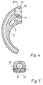
- the coupling consists of a coupling link 4, which is shown in figs. 2 and 3, and a coupling hole 16 in the hook-shaped part 2, which is shown in figs. 4 and 5.
- the coupling link 4 comprises a plug-shaped part 14 with a through-going hole which has an enlarged part 5, so that acoustically it suits the aid's sound producer. Under the through-going hole there can be disposed a flange with a sound hole 6 which acoustically suits the aid's microphone.
- a partly peripheral groove 10 having an arcuate profile, in that a part of the one side of the groove 12 is removed, for example by making it flat, see particularly fig. 3.
- a peripheral groove 9 is provided in which an 0-ring 8 can be placed.
- the transition 7 between the plug-shaped part 14 and the actual coupling link 4 is rounded or formed so that it fits in a correspondingly shaped hole in the hearing aid 1, see particularly fig. 1, where the positioning of the 0- ring 8 is also shown.
- a coupling hole 16 with a circular bevel 15 suitable for the 0-ring there is a coupling hole 16 with a circular bevel 15 suitable for the 0-ring.
- a further hole 17 which reaches in to the hole 16, see fig. 5, so that a dowel 11 which is inserted in and fills out the hole 17 forms a projecting wall part which can engage with the groove 10 when the coupling is assembled.
- the dowel 11 is inserted in the hole 17 by press-fitting, where it is also secured by a blob of glue 13.
- a hook-shaped part 2 When a hook-shaped part 2 is required to be mounted on a hearing aid 1, this is carried out by turning the hook-shaped part 180° in relation to the position in which it is shown in fig. 1. Using light pressure, the hook-shaped part 2 is introduced in over the coupling link 4, which fits into the coupling hole 16. The hook-shaped part 2 is then turned around the axis of the plug 14 to that position shown in fig. 1. As soon as the hook-shaped part 2 has been turned so much that the dowel 11 engages in the groove 10, the parts can no longer be separated without deforming them under elastic strain. The hook-shaped part 2 can be turned in relation to the hearing aid without the parts being loosened, in that the O-ring 8 provides suitable friction. Regardless of the position of the hook-shaped part 2 in relation to the housing 1, there is a constant and unchanged acoustic connection from the sound producer through the hole in the coupling link 4 to the channel in the hook-shaped part 2.
- the coupling link 4 is made as a moulded unit, preferably from a hard plastics material.
Abstract
Description
- The invention relates to a coupling for use in the securing of a hook-shaped sound part on a behind-the-ear hearing aid.
- Hearing aids for placing behind the ear often consist of a hearing aid housing containing a microphone, amplifier with regulation elements, battery and sound producer, and a hook-shaped part which is hollow and has one end arranged to be connected with the sound output of the housing and which serves, by means of a through-going channel, to transfer the sound from the sound producer to the ear, preferably through a tube which is mounted on the hook-shaped part and which conducts the audio signal to an earplug mounted on the tube. By virtue of its form, the hook-shaped part also contributes towards bearing the hearing aid directly on the outer ear.
- With the known hearing aids, the hook-shaped part is normally formed from a semi-stiff plastic material, for example polyethylene, which is easy to mould to a suitable shape. The hook-shaped part is secured to the hearing aid housing by means of a plug of hard plastic material or metal extending from the housing, said plug being provided with an external thread with evenly rounded thread tops. Without the hole in the hook-shaped part being provided with an internal thread, said hook-shaped part can be screwed on to the threaded plug because it is made of semi-stiff material, which by elastic deformation formed a thread corresponding to the threaded plug. For the coupling together to be sufficiently solid, one must, however, surround that end of the hook-shaped part which is led in over the plug with a stiffening ring of metal. The reason why it is not possible to use a conventional threaded assembly is that the user must be able to turn the hook-shaped part and to adjust it individually to suit his own ear, while at the same time ensuring that the hook-shaped part doss not sit too loosely on the aid or that the thread be ruined. In addition the hook-shaped part must be such as to allow the user to remove it when it needs to be cleaned or exchanged.
- There is also a need for the hook-shaped sound part to be exchangeable when the acoustic characteristics of the aid need to be changed. For this purpose there are produced hook-shaped parts with different acoustic qualities, viz. with different sound channels or with built-in acoustic filters or other acoustic adjustment devices.
- The choice of materials enabling the hook-shaped part to be formed as explained above is limited, and therefore, polyethylene, which is semi-stiff, is often used. However, this material makes it necessary to use a metal ring as reinforcement and the whiteness of the plastic as well as the shiny brightness of the metal ring give the hearing aid an appearance which is unattractive.
- From the description of US
Patent Specification 3 813 499 is known a behind-the-ear hearing aid of the kind defined in the preamble ofclaim 1 and according to which the hook-shaped sound part is connected to the hearing-aid part by means of a conventional bayonet lock comprising two locking lugs on the plug-shaped part of the hearing-aid part. A correspondingly shaped coupling hole in the sound part is formed with recesses extending inwards from the coupling hole in the form of internal grooves in the sound part. To manufacture a sound part of this kind by means of the conventional plastic moulding technique it is necessary to mould the sound part from a soft material to allow the mould core to be removed from the moulded blank by being pulled over the mould parts designed to produce the recesses. - On account of the soft material it is probably necessary to reinforce the bayonet lock by means of a peripheral ring or similar means. In addition, the range over which bayonet locks of this kind may be adjusted is not particularly wide, for which reason it may be hazardous to turn the hook-shaped part relative to the hearing-aid part without the two parts coming apart.
- The object of the invention in accordance with the subject application is to provide a bayonet coupling intended to interconnect a hook-shaped sound part with a hearing aid which is designed in such a manner as to provide complete freedom of choice as regards the kind of material to be used to produce the hook-shaped part as well as to provide a very large angular range for the positioning of the hook-shaped part on the hearing-aid part.
- This object is achieved by designing the coupling part in the manner appearing from the characterizing clause of
claim 1. Owing thereto, it becomes possible to choose from a large number of different materials to manufacture the components of the coupling because the projecting wall part, that is the dowel may be inserted after removal of the mould core. For instance, the hook-shaped part may be made from rigid plastics, for instance, from impact-resisting acrylic plastics which may be delivered in a large range of different colours and one is no longer restricted to use the common soft whitish plastics that is not particularly attractive in appearance and which needs to be reinforced on account of its poor strength. By varying the distance of extension of the peripheral groove over the circumference of the plug shaped part it becomes possible to change the relationship between the extent of the free position and the interconnected position. It has been found to be practical for the free position to extend over approx. 10 to 30° and the interconnected position to extend over approx. 330 to 350°, although variations are possible, depending on use and wish. In addition, the invention provides a very reliable coupling which with a suitable choice of materials is also secured against damage, in that one can actually remove the hook-shaped part without destroying parts of the bayonet coupling, even though it is mounted in the interconnected position. - The coupling is preferably provided with a. gasket as presented in
claim 2. By arranging a circular gasket, a so-called O-ring an essentially airtight assembly is obtained in a simple manner. This is of significance for the acoustic adaptation between the sound outlet and the sound channel in the hook-shaped part. Moreover, by using a flexible gasket a certain elasticity is obtained as well as some friction between the hook-shaped part and the housing of the hearing aid, allowing the hook-shaped part to be retained in any position irrespective of free position. - By forming the coupling as presented in
claim 3, a very well-defined free position is obtained, thus making it simple to assemble and separate the parts, also for persons whose hands shake a great deal or who have a poor eyesight, the reason being that it is a quite simple matter to find the free position without looking at the aid. -
Claims 4 and 5 define ways of manufacturing the various components by using techniques which are advantageous from a production point of view. Also as regards repairs it is an advantage to form the plug art as a separate component. - The invention will now be described in more detail with reference to the drawing, which shows an example of a preferred embodiment, and where
- Fig. 1 shows, partly in section, a hearing aid with a coupling according to the invention,
- Fig. 2 shows a plane section in a coupling link for use in the coupling according to the invention,
- Fig. 3 shows the coupling link in fig. 2, but seen in the direction III-III,
- Fig. 4 shows a plane section in a hook-shaped part on a larger scale, showing the construction of the coupling hole, and
- Fig. 5 shows a plane section in the hook-shaped part in fig. 4, seen in the direction V-V.
- In the drawing, the hearing aid itself or the housing of the hearing aid is indicated by the reference figure 1, while 2 indicates the hook-shaped part, also called a hook. In fig. 1 the two parts as seen in the coupled together condition, in that
coupling link 4, which is seen more clearly in figs. 2 and 3, with an 0-ring 8 is inserted and secured in a coupling hole in the hook-shaped sound part 2. The rest of theactual hearing aid 1, i.e. its electrical and acoustic arrangements, are not shown or discussed, since these do not form a part of the present invention which relates only to the coupling between thehousing 1 and the hook-shaped sound part 2. The opening 3 in the hook-shaped part serves to ensure the passage of sound into the microphone opening in the hearing aid. - In a preferred embodiment, the coupling consists of a
coupling link 4, which is shown in figs. 2 and 3, and acoupling hole 16 in the hook-shaped part 2, which is shown in figs. 4 and 5. - The
coupling link 4 comprises a plug-shaped part 14 with a through-going hole which has an enlarged part 5, so that acoustically it suits the aid's sound producer. Under the through-going hole there can be disposed a flange with asound hole 6 which acoustically suits the aid's microphone. In the plug-shaped part 14 there is formed a partlyperipheral groove 10 having an arcuate profile, in that a part of the one side of thegroove 12 is removed, for example by making it flat, see particularly fig. 3. Between theother side 18 of the groove and thecoupling link 4, aperipheral groove 9 is provided in which an 0-ring 8 can be placed. Moreover, thetransition 7 between the plug-shaped part 14 and theactual coupling link 4 is rounded or formed so that it fits in a correspondingly shaped hole in thehearing aid 1, see particularly fig. 1, where the positioning of the 0-ring 8 is also shown. - In the hook-
shaped part 2, see figs. 4 and 5; there is acoupling hole 16 with acircular bevel 15 suitable for the 0-ring. Provided at right angles to thehole 16 is afurther hole 17 which reaches in to thehole 16, see fig. 5, so that adowel 11 which is inserted in and fills out thehole 17 forms a projecting wall part which can engage with thegroove 10 when the coupling is assembled. Thedowel 11 is inserted in thehole 17 by press-fitting, where it is also secured by a blob ofglue 13. - When a hook-
shaped part 2 is required to be mounted on ahearing aid 1, this is carried out by turning the hook-shaped part 180° in relation to the position in which it is shown in fig. 1. Using light pressure, the hook-shaped part 2 is introduced in over thecoupling link 4, which fits into thecoupling hole 16. The hook-shaped part 2 is then turned around the axis of theplug 14 to that position shown in fig. 1. As soon as the hook-shaped part 2 has been turned so much that thedowel 11 engages in thegroove 10, the parts can no longer be separated without deforming them under elastic strain. The hook-shaped part 2 can be turned in relation to the hearing aid without the parts being loosened, in that the O-ring 8 provides suitable friction. Regardless of the position of the hook-shaped part 2 in relation to thehousing 1, there is a constant and unchanged acoustic connection from the sound producer through the hole in thecoupling link 4 to the channel in the hook-shaped part 2. - Since the interconnection is based on a bayonet lock which can be turned in either direction and all the way around, one is completely free as regards the choice of materials for the
hearing aid housing 1 and the hook-shaped part 2. For example, it is thus possible to make the hook-shaped sound part of impact-resisting acrylic plastic, which can be coloured or tinted as desired. Furthermore, and of special importance, is the possibility of avoiding the use of any form of unsightly metal reinforcement. Thecoupling link 4 is made as a moulded unit, preferably from a hard plastics material. - In the drawing is shown an example of one embodiment of the invention where the microphone inlet is shown below the sound outlet, but this is only an-example of the application of the invention. It will be obvious to those familiar with the technique that the disposition and dimensioning of a coupling according to the invention can be effected in many different ways wouthout deviating from the scope of the invention, including a large variety of possibilities of positioning the components, particularly the plug part.
Claims (5)
Priority Applications (1)
| Application Number | Priority Date | Filing Date | Title |
|---|---|---|---|
| AT83850290T ATE34267T1 (en) | 1982-11-05 | 1983-11-01 | COUPLING FOR ATTACHING A HOOK-SHAPED SOUND LINE TO A HEARING AID WORN BEHIND THE EAR. |
Applications Claiming Priority (2)
| Application Number | Priority Date | Filing Date | Title |
|---|---|---|---|
| DK4920/82 | 1982-11-05 | ||
| DK492082A DK148230C (en) | 1982-11-05 | 1982-11-05 | REAR-EAR HEARING DEVICE WITH A HOOK-SOUND SOUND |
Publications (2)
| Publication Number | Publication Date |
|---|---|
| EP0108734A1 EP0108734A1 (en) | 1984-05-16 |
| EP0108734B1 true EP0108734B1 (en) | 1988-05-11 |
Family
ID=8137866
Family Applications (1)
| Application Number | Title | Priority Date | Filing Date |
|---|---|---|---|
| EP83850290A Expired EP0108734B1 (en) | 1982-11-05 | 1983-11-01 | Coupling for use in the securing of a hook-shaped sound part on a behind-the-ear hearing aid |
Country Status (5)
| Country | Link |
|---|---|
| US (1) | US4564955A (en) |
| EP (1) | EP0108734B1 (en) |
| AT (1) | ATE34267T1 (en) |
| DE (1) | DE3376614D1 (en) |
| DK (1) | DK148230C (en) |
Families Citing this family (38)
| Publication number | Priority date | Publication date | Assignee | Title |
|---|---|---|---|---|
| US4720857A (en) * | 1985-12-06 | 1988-01-19 | Plantronics, Inc. | Miniaturized headset for two-way voice communication |
| DK155069C (en) * | 1986-06-30 | 1989-07-17 | Oticon Electronics As | HAENGEBOEJLE, A COLD HOOK, FOR BAG-EARN HEARING DEVICE |
| CH673919A5 (en) * | 1987-08-11 | 1990-04-12 | Rexton Int Ag | |
| NL8802518A (en) * | 1988-10-13 | 1990-05-01 | Philips Nv | IN-THE-EAR HEARING AID. |
| US5446788A (en) * | 1992-09-29 | 1995-08-29 | Unex Corporation | Adjustable telephone headset |
| US6411709B1 (en) | 1994-11-17 | 2002-06-25 | Unex Corporation | Flexible microphone boom |
| US6421426B1 (en) | 1997-08-15 | 2002-07-16 | Gn Netcom/Unex Inc. | Infrared wireless headset system |
| EP1254587B1 (en) * | 2000-02-09 | 2003-07-16 | Phonak Ag | Hearing device |
| US6894456B2 (en) * | 2001-11-07 | 2005-05-17 | Quallion Llc | Implantable medical power module |
| US7003356B2 (en) * | 2002-03-08 | 2006-02-21 | Quallion Llc | Battery terminal sealing and supporting device and method |
| ATE466457T1 (en) * | 2002-07-12 | 2010-05-15 | Oticon As | SUSPENSION AGENT FOR A TRANSDUCER |
| DK1997348T3 (en) * | 2006-03-21 | 2017-07-24 | Widex As | EXCHANGED LOCATION TO MAKE A LEADER TO A HEARING |
| US8452021B2 (en) * | 2007-04-17 | 2013-05-28 | Starkey Laboratories, Inc. | Real ear measurement system using thin tube |
| DE102007033289A1 (en) * | 2007-07-17 | 2009-01-22 | Siemens Audiologische Technik Gmbh | Arrangement with carrying hook for hearing aids and associated method |
| DE102008007553A1 (en) * | 2008-02-05 | 2009-08-13 | Siemens Medical Instruments Pte. Ltd. | Hearing aid with acoustic damper |
| DK2107830T3 (en) * | 2008-03-31 | 2014-07-28 | Starkey Lab Inc | Method and apparatus for measuring on an actual ear for receiving devices in the ear canal |
| EP2107831A3 (en) * | 2008-03-31 | 2010-12-29 | Starkey Laboratories, Inc. | Real ear measurement adaptor with internal sound conduit |
| WO2010016925A1 (en) | 2008-08-08 | 2010-02-11 | Starkey Laboratories, Inc. | System for measuring sound pressure level |
| CA2639555A1 (en) | 2008-08-11 | 2008-12-15 | Hyman Ngo | High definition litho applique and emblems |
| US8781141B2 (en) | 2008-08-27 | 2014-07-15 | Starkey Laboratories, Inc. | Modular connection assembly for a hearing assistance device |
| USD612840S1 (en) | 2008-12-18 | 2010-03-30 | Plantronics, Inc. | Communications headset |
| USD612834S1 (en) | 2008-12-18 | 2010-03-30 | Plantronics, Inc. | Communications headset |
| US8542841B2 (en) * | 2009-01-12 | 2013-09-24 | Starkey Laboratories, Inc. | Method to estimate the sound pressure level at eardrum using measurements away from the eardrum |
| US9107015B2 (en) * | 2009-03-27 | 2015-08-11 | Starkey Laboratories, Inc. | System for automatic fitting using real ear measurement |
| DK2293600T3 (en) * | 2009-07-27 | 2017-08-28 | Sivantos Pte Ltd | Processing unit and receiving unit for a hearing aid and hearing aid |
| US8781144B2 (en) | 2009-08-17 | 2014-07-15 | Phonak Ag | Attachment of a hook to a hearing device |
| DE102010009702A1 (en) * | 2010-03-01 | 2011-10-06 | Siemens Medical Instruments Pte. Ltd. | Hearing device with a guide element, in particular a sound tube |
| US9161131B2 (en) * | 2010-03-25 | 2015-10-13 | K&E Holdings, LLC | Stereo audio headphone apparatus for a user having a hearing loss and related methods |
| US9049526B2 (en) * | 2011-03-19 | 2015-06-02 | Starkey Laboratories, Inc. | Compact programming block connector for hearing assistance devices |
| US9913052B2 (en) | 2013-11-27 | 2018-03-06 | Starkey Laboratories, Inc. | Solderless hearing assistance device assembly and method |
| US9906879B2 (en) | 2013-11-27 | 2018-02-27 | Starkey Laboratories, Inc. | Solderless module connector for a hearing assistance device assembly |
| USD784290S1 (en) * | 2015-12-09 | 2017-04-18 | Plantronics, Inc. | Communications headset |
| USD784291S1 (en) * | 2015-12-09 | 2017-04-18 | Plantronics, Inc. | Communications headset |
| USD789331S1 (en) * | 2015-12-09 | 2017-06-13 | Plantronics, Inc. | Microphone boom for a communications headset |
| JP6030799B1 (en) * | 2016-06-14 | 2016-11-24 | リオン株式会社 | Hearing aid |
| USD838688S1 (en) * | 2017-05-07 | 2019-01-22 | Xiaoliang Liu | Wireless headset |
| USD866507S1 (en) * | 2018-07-13 | 2019-11-12 | Shenzhen Fushike Electronic Co., Ltd. | Wireless headset |
| DE102020208897A1 (en) * | 2020-07-16 | 2022-01-20 | Sivantos Pte. Ltd. | Hearing aid, in particular BTE hearing aid |
Family Cites Families (5)
| Publication number | Priority date | Publication date | Assignee | Title |
|---|---|---|---|---|
| GB732186A (en) * | 1952-06-06 | 1955-06-22 | Scandinavian Agencies Corp Ltd | Improvements relating to conduit couplings |
| US3491214A (en) * | 1967-01-12 | 1970-01-20 | Otarion Electronics Inc | Hearing aid with adjustable sound inlet means |
| US3812300A (en) * | 1970-12-02 | 1974-05-21 | Beltone Electronics Corp | Improved receiver assembly incorporating acoustical enclosure for receiver |
| US3813499A (en) * | 1972-11-08 | 1974-05-28 | Sonotone Corp | Hearing aid nozzle with resilient bayonet lock |
| DK150840C (en) * | 1978-12-15 | 1988-06-06 | Gn Danavox As | HOOK SHAPE PART FOR A REAR EAR HEARING DEVICE |
-
1982
- 1982-11-05 DK DK492082A patent/DK148230C/en not_active IP Right Cessation
-
1983
- 1983-10-19 US US06/543,291 patent/US4564955A/en not_active Expired - Fee Related
- 1983-11-01 EP EP83850290A patent/EP0108734B1/en not_active Expired
- 1983-11-01 DE DE8383850290T patent/DE3376614D1/en not_active Expired
- 1983-11-01 AT AT83850290T patent/ATE34267T1/en not_active IP Right Cessation
Also Published As
| Publication number | Publication date |
|---|---|
| DK492082A (en) | 1984-05-06 |
| DE3376614D1 (en) | 1988-06-16 |
| EP0108734A1 (en) | 1984-05-16 |
| DK148230B (en) | 1985-05-06 |
| ATE34267T1 (en) | 1988-05-15 |
| DK148230C (en) | 1985-09-23 |
| US4564955A (en) | 1986-01-14 |
Similar Documents
| Publication | Publication Date | Title |
|---|---|---|
| EP0108734B1 (en) | Coupling for use in the securing of a hook-shaped sound part on a behind-the-ear hearing aid | |
| US4607720A (en) | Hearing aid | |
| US4069400A (en) | Modular in-the-ear hearing aid | |
| US4585089A (en) | Coupling element for a hearing aid | |
| US8055002B2 (en) | Method and apparatus for modular hearing aid | |
| US4716985A (en) | In-the-ear hearing aid | |
| US5488205A (en) | Hearing aid tubing connector | |
| US8416974B2 (en) | Hearing aid with connecting element serving for retention in concha | |
| DK174395B1 (en) | Hearing aid | |
| US20050002539A1 (en) | Retaining member for an earpiece | |
| CN107613444B (en) | Hearing aid | |
| CA2264673A1 (en) | A compact modular in-the-ear hearing aid | |
| AU2006340658A1 (en) | Interchangeable attachment means for attaching a conductor to a hearing aid | |
| US20100027825A1 (en) | Ear mold for a hearing device | |
| US4679650A (en) | Hearing aid ear mold end piece for the auditory canal and hearing aid ear mold | |
| CA2609362A1 (en) | A hook for a hearing aid | |
| JPS61131700A (en) | Hearing aid | |
| GB2203379A (en) | Making hearing aids | |
| CN111246359A (en) | Micro auditory canal type hearing aid | |
| US7635047B2 (en) | Hearing aid | |
| JPH0430879Y2 (en) | ||
| KR20030020798A (en) | Free hearing aid providing multi-shape and multi-function | |
| JPH036077Y2 (en) | ||
| US11115744B2 (en) | Audio device with conduit connector | |
| JPS5824547Y2 (en) | Sound pressure type electric ↓-acoustic transducer |
Legal Events
| Date | Code | Title | Description |
|---|---|---|---|
| PUAI | Public reference made under article 153(3) epc to a published international application that has entered the european phase |
Free format text: ORIGINAL CODE: 0009012 |
|
| AK | Designated contracting states |
Designated state(s): AT BE CH DE GB LI NL SE |
|
| 17P | Request for examination filed |
Effective date: 19841106 |
|
| 17Q | First examination report despatched |
Effective date: 19860320 |
|
| RAP1 | Party data changed (applicant data changed or rights of an application transferred) |
Owner name: GN DANAVOX A/S |
|
| GRAA | (expected) grant |
Free format text: ORIGINAL CODE: 0009210 |
|
| AK | Designated contracting states |
Kind code of ref document: B1 Designated state(s): AT BE CH DE GB LI NL SE |
|
| PG25 | Lapsed in a contracting state [announced via postgrant information from national office to epo] |
Ref country code: NL Effective date: 19880511 Ref country code: BE Effective date: 19880511 Ref country code: AT Effective date: 19880511 |
|
| REF | Corresponds to: |
Ref document number: 34267 Country of ref document: AT Date of ref document: 19880515 Kind code of ref document: T |
|
| PG25 | Lapsed in a contracting state [announced via postgrant information from national office to epo] |
Ref country code: SE Effective date: 19880531 |
|
| REF | Corresponds to: |
Ref document number: 3376614 Country of ref document: DE Date of ref document: 19880616 |
|
| NLV1 | Nl: lapsed or annulled due to failure to fulfill the requirements of art. 29p and 29m of the patents act | ||
| PLBI | Opposition filed |
Free format text: ORIGINAL CODE: 0009260 |
|
| 26 | Opposition filed |
Opponent name: SIEMENS AKTIENGESELLSCHAFT, BERLIN UND MUENCHEN Effective date: 19890203 |
|
| PGFP | Annual fee paid to national office [announced via postgrant information from national office to epo] |
Ref country code: GB Payment date: 19921026 Year of fee payment: 10 |
|
| PLBN | Opposition rejected |
Free format text: ORIGINAL CODE: 0009273 |
|
| STAA | Information on the status of an ep patent application or granted ep patent |
Free format text: STATUS: OPPOSITION REJECTED |
|
| PGFP | Annual fee paid to national office [announced via postgrant information from national office to epo] |
Ref country code: CH Payment date: 19921221 Year of fee payment: 10 |
|
| PGFP | Annual fee paid to national office [announced via postgrant information from national office to epo] |
Ref country code: DE Payment date: 19921224 Year of fee payment: 10 |
|
| 27O | Opposition rejected |
Effective date: 19920808 |
|
| PG25 | Lapsed in a contracting state [announced via postgrant information from national office to epo] |
Ref country code: GB Effective date: 19931101 |
|
| PG25 | Lapsed in a contracting state [announced via postgrant information from national office to epo] |
Ref country code: LI Effective date: 19931130 Ref country code: CH Effective date: 19931130 |
|
| GBPC | Gb: european patent ceased through non-payment of renewal fee |
Effective date: 19931101 |
|
| REG | Reference to a national code |
Ref country code: CH Ref legal event code: PL |
|
| PG25 | Lapsed in a contracting state [announced via postgrant information from national office to epo] |
Ref country code: DE Effective date: 19940802 |