EP0108371B1 - Einrichtung zur Steuerung und/oder Messung des Durchsatzes eines strömenden Mediums - Google Patents
Einrichtung zur Steuerung und/oder Messung des Durchsatzes eines strömenden Mediums Download PDFInfo
- Publication number
- EP0108371B1 EP0108371B1 EP83110878A EP83110878A EP0108371B1 EP 0108371 B1 EP0108371 B1 EP 0108371B1 EP 83110878 A EP83110878 A EP 83110878A EP 83110878 A EP83110878 A EP 83110878A EP 0108371 B1 EP0108371 B1 EP 0108371B1
- Authority
- EP
- European Patent Office
- Prior art keywords
- flow
- spindle
- aid
- opening
- pressure
- Prior art date
- Legal status (The legal status is an assumption and is not a legal conclusion. Google has not performed a legal analysis and makes no representation as to the accuracy of the status listed.)
- Expired
Links
- 239000012530 fluid Substances 0.000 title claims abstract description 12
- 238000012545 processing Methods 0.000 claims abstract description 9
- XEEYBQQBJWHFJM-UHFFFAOYSA-N Iron Chemical compound [Fe] XEEYBQQBJWHFJM-UHFFFAOYSA-N 0.000 claims description 12
- 230000001276 controlling effect Effects 0.000 claims description 11
- 238000012856 packing Methods 0.000 claims description 11
- 229910052742 iron Inorganic materials 0.000 claims description 6
- 230000005291 magnetic effect Effects 0.000 claims description 5
- 229910000859 α-Fe Inorganic materials 0.000 claims description 3
- 239000002184 metal Substances 0.000 claims description 2
- 229910052751 metal Inorganic materials 0.000 claims description 2
- 230000000284 resting effect Effects 0.000 claims description 2
- 230000001105 regulatory effect Effects 0.000 claims 2
- 238000009423 ventilation Methods 0.000 description 5
- 239000012528 membrane Substances 0.000 description 4
- 230000000694 effects Effects 0.000 description 3
- 238000000034 method Methods 0.000 description 3
- 230000003247 decreasing effect Effects 0.000 description 2
- 230000001419 dependent effect Effects 0.000 description 2
- 238000013461 design Methods 0.000 description 2
- 238000001595 flow curve Methods 0.000 description 2
- 230000006870 function Effects 0.000 description 2
- 230000005484 gravity Effects 0.000 description 2
- 238000005259 measurement Methods 0.000 description 2
- 230000003287 optical effect Effects 0.000 description 2
- 230000000087 stabilizing effect Effects 0.000 description 2
- 238000000418 atomic force spectrum Methods 0.000 description 1
- 230000005540 biological transmission Effects 0.000 description 1
- 230000007423 decrease Effects 0.000 description 1
- 238000010586 diagram Methods 0.000 description 1
- 230000009977 dual effect Effects 0.000 description 1
- 230000005294 ferromagnetic effect Effects 0.000 description 1
- 238000001914 filtration Methods 0.000 description 1
- 239000007789 gas Substances 0.000 description 1
- 230000001771 impaired effect Effects 0.000 description 1
- 239000012535 impurity Substances 0.000 description 1
- 239000007788 liquid Substances 0.000 description 1
- 238000005461 lubrication Methods 0.000 description 1
- 239000000696 magnetic material Substances 0.000 description 1
- 230000035945 sensitivity Effects 0.000 description 1
- 230000003068 static effect Effects 0.000 description 1
Images


Classifications
-
- G—PHYSICS
- G05—CONTROLLING; REGULATING
- G05D—SYSTEMS FOR CONTROLLING OR REGULATING NON-ELECTRIC VARIABLES
- G05D7/00—Control of flow
- G05D7/01—Control of flow without auxiliary power
- G05D7/0126—Control of flow without auxiliary power the sensing element being a piston or plunger associated with one or more springs
- G05D7/0133—Control of flow without auxiliary power the sensing element being a piston or plunger associated with one or more springs within the flow-path
- G05D7/014—Control of flow without auxiliary power the sensing element being a piston or plunger associated with one or more springs within the flow-path using sliding elements
-
- F—MECHANICAL ENGINEERING; LIGHTING; HEATING; WEAPONS; BLASTING
- F24—HEATING; RANGES; VENTILATING
- F24F—AIR-CONDITIONING; AIR-HUMIDIFICATION; VENTILATION; USE OF AIR CURRENTS FOR SCREENING
- F24F11/00—Control or safety arrangements
- F24F11/70—Control systems characterised by their outputs; Constructional details thereof
- F24F11/72—Control systems characterised by their outputs; Constructional details thereof for controlling the supply of treated air, e.g. its pressure
- F24F11/74—Control systems characterised by their outputs; Constructional details thereof for controlling the supply of treated air, e.g. its pressure for controlling air flow rate or air velocity
-
- G—PHYSICS
- G05—CONTROLLING; REGULATING
- G05D—SYSTEMS FOR CONTROLLING OR REGULATING NON-ELECTRIC VARIABLES
- G05D7/00—Control of flow
- G05D7/005—Control of flow characterised by the use of auxiliary non-electric power combined with the use of electric means
Definitions
- the present invention concerns a means for controlling and/or measuring the flow of a running fluid wherein the throttling of the flow is controlled utilizing the fluid's own differential pressure arising from the flow, i.e. a means as described in the preamble of claim 1.
- the means, or valve, of this kind consists of a cylindrical housing which has been mounted in a ventilation duct. To the housing has been axially and integrally adjoined a bearing housing, and to the front end thereof the bottom part of the valve.
- the spindle of the valve has been disposed to slide, supported by a linear bearing placed in the bearing housing.
- On the front end of the spindle has been mounted the main valve disc and on the rear end the control valve disc.
- the rear end of the bearing housing is closed with a seat ring or equivalent, said ring constituting together with the control valve disc, by the aid thereof, an opening of adjustable area.
- the main valve disc has also been provided with an opening.
- the bottom part of the valve and the main valve disc have been interconnected by an elastic annular membrane.
- the bearing housing with its seat ring, the bottom of the valve and the main valve disc constitute an elastic cylindrical closed volume with an inlet and outlet opening.
- a spring In conjunction with the main valve disc, in extension of the valve spindle, has been placed a spring, one end of which rests in the housing of the central part of the valve cover.
- the valve cover provided with a flow opening has been attached by threads to the body.
- the operation of the means is based on the cascade phenomenon well-known in pneumatics.
- the relationship of the differential pressure in the closed volume and in the passage to the environment and to the differential pressure in the closed volume is in a certain way dependent on the ratio of the surface areas of the closed space's apertures.
- Selection of the volumetric flow range of the valve is made by turning the valve cover. Hereby, it moves axially in the direction of the spindle and acts through the counter-spring on the spindle and on the opening between the control valve disc and the seat and thereby on the equilibrium position of the valve and on the volumetric flow passing through the flow opening.
- a drawback of the apparatus described in the foregoing is for instance that the selection of volumetric flow range has to be made by hand, by rotating the cover.
- the means is used as flat-specific ventilation controller in the ventilation system of a residential building, the dwellers must themselves adjust the means from its normal control position to the high-power position and back.
- the object of the invention is to eliminate the drawbacks mentioned and, in general, to increase the control capability of the means, based on the cascade principle, meant for control and/or stabilizing of the flow of a running fluid, gas or liquid, and to enable almost simultaneously the measurement of the fluid's pressure. and/or volumetric flow.
- the means of the invention, or the equivalent means disclosed in the Patent No. 60069 may be used for measuring flow by mounting on the housing of the means directly or by the aid of supports a mechanical, electromechanical, magnetic, electromagnetic, optical or other sensing member measuring the motion, position or distance of a part of any component of the cylinder volume/piston combination moving axially in the direction of the flow, the signal thereby supplied being indicated and carried as an electrical signal to a suitable processing means, such as an amplifier, and further to a data processing unit such as a microprocessor.
- This may compute from the data stored in the first part of its memory unit, such as e.g. the characteristic curves of the valve, the variations in volumetric flow, the changes, the flow pressures, or other equivalent control variables.
- the results of calculation are compared with the desired values stored in the second part of the memory unit, and on the basis of the comparison the control is carried out, utilizing the adjustment of the ratio of the surface areas of the openings of the cylinder volume, known in the art, for producing the desired flow or pressure.
- This is done by means of a suitable actuator, either by shifting the seat of the control valve, by directing on the spindle or on the main valve disc an extra axial force, or by controlling the surface area of the first opening shifted outside the means by the aid of a projection. It is natural that a means like the one described briefly in the foregoing may, owing to the characteristics mentioned above, also be advantageously used for controlling external systems.
- the cover provided with a flow opening is preferably fixed and the spring (if used) is so disposed inside the cylinder volume/piston assembly that the direction of its increasing load is opposite to that in the means of the Patent No. 60069.
- the means may also be controlled from the outside, either with or without a timer, or by another suitable control.
- the spring may be replaced by gravity, this being accomplished by inclining the means from its axial horizontal position in an expedient direction, or by an electromagnetic force.
- the means has been placed in a duct in which prevails vacuum in comparison with the pressure in the cylinder volume.
- the means may equally be placed outside the duct and controlled by its vacuum. In this case, however, the effect of the inversion on the formula to be given below has to be observed.
- the main valve disc may be closing either with or against the flow.
- the control cone may be replaced with a body of arbitrary shape which gives rise to the changes in the surface area ratios of the openings required by the control function.
- the means may also be disposed in an enclosed space, such as a closed duct, and controlled from outside this space because the cover provided with a flow opening is fixed.
- the means restores itself to the desired position, e.g. to the economy position after high-power operation. Thereby, the dwellers are not required to be economy-conscious.
- the filtering of the control flow has been arranged to be outside the entire means, whereby e.g. replacement of the filter of the means mounted in the duct is simple. All moving components of the control/measuring circuit of the means are located in a filtered space with reference to the control flow. Therefore, foreign bodies or other impurities cannot enter the cylinder volume to cause trouble in the operation of the valve.
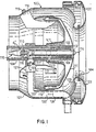
- the design of the valve 100 depicted in Fig. 1 is as follows. To the housing 101, positioned on the end of the exhaust air duct terminating on the wall of the room, is attached the bottom part 107 of the valve by the aid of supports 118 and screws 119, to said bottom part in turn being connected with a crimp join the bearing housing 106. On the front end of the bearing housing has been disposed a standard-made linear bearing 108 with endless ball races, said bearing being provided with a conical sleeve 109 for adjustment of play. Supported by the bearing, the spindle 113 moves axially, provided at its front end with a main valve disc 111 and at its rear end with a control cone, or control valve disc, 115.
- the lubrication bore provided on the front end of the spindle is closed by a plastic plug 114.
- a spring 117 between the valve discs 111, 115 so that one end of the spring rests against the linear bearing, and the other against an adjusting nut 116 placed on the spindle or against a fixed stop.
- the end of the spindle is provided with threads, along which the adjusting nut may be moved.
- the opening d 2 ' is disposed in the seat ring 110 at the rear end of the bearing housing.
- the spring mounted on the spindle 113 may in some cases be left out altogether.
- the valve 100 may be mounted in a position deviating from the axial horizontal plane (e.g. instead of wall mounting for ceiling mounting), and by gravity action acting on the piston combination 111, 113, 115 is replaced the spring force caused by the spring 117.
- the spindle 113 may be threaded over its entire central portion, whereby by the aid of the adjusting nut 116 the smallest opening of the valve can be defined and in this manner the valve prevented from closing completely.
- the spring may in the conventional horizontal position of the valve 100 be replaced by electromagnetic arrangements, e.g. as shown in Fig. 2.
- the bottom 107 of the valve and the main valve disc 111 are hermetically and elastically interconnected by a membrane 112, and the juncture is protected by an envelope 122, which also serves as a flow baffle.
- the seat ring of the valve consists of the valve cover, consisting of two components: an inner shell 102 and an outer shell 103, these two being provided with a packing 104.
- the outer shell is affixed to the housing of the valve with a short thread at its front end, and the juncture is sealed with the packing 105.
- To the envelope 122 has been attached a guide 124, which prevents the cylinder from rotating when it is cleaned, while permitting axial motion.
- the bearing housing 106 is provided with a tube or projection 120. They have been interconnected by a connector 121. Behind the bearing 108, the housing has also been provided with bores 123 which enable the control air to flow past the bearing. Both the opening 123' and the projection 120 and the bores 123 in combination must have a cross section area which is larger by one order of magnitude than the opening d2', in order to prevent the cascade effect in the instance in question.
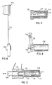
- Fig. 2 represents either a control or a measuring means, depending on in what type of circuit the solenoid 134 has been incorporated and on the magnetic properties of the body 135 moving inside the solenoid and/or in its immediate vicinity.
- a non-magnetic sleeve 131 has been affixed by means of threads, in which possibly a support bearing 132 has been mounted.
- an extension spindle 133 made of a non-magnetic material, and which is supported by the bearing mentioned and has been provided with a soft iron body 135.
- a solenoid 134 has been mounted on the rear end of the support bearing sleeve 131. It has been connected to an adjustable power supply. As current is conducted into the solenoid, it is magnetized and acts on the spindle by directing on it by mediation of the soft iron body an axial force of a given magnitude, proportional to the current intensity.
- it is possible to control or change the volumetric flow control range of the valve by increasing or decreasing the loading of the spring 117 by the aid of the electromagnet constituted by the solenoid.
- the spring 117 may also be completely omitted from the valve and the spring load may be replaced by an electromagnetic force generated by the solenoid 134, proportional to the current intensity. By means of an axial force such as this, the dynamic or other forces now acting on the main valve disc 111 would be compensated.
- the solenoid 134 disposed in the manner shown in Fig. 2, or on the other end of the spindle in front of the valve, may be used for measuring the flow pressure or differential pressure and the volumetric flow by replacing the soft iron body with a ferrite body 135 or with a body having equivalent magnetic properties, and by connecting the solenoid to a suitable oscillator circuit.
- the ferrite body 135 acts in a manner known in the art, depending on the distance of the solenoid, so that the frequency of the oscillator circuit changes, and based thereon the relative position of the spindle can be determined.
- a frequency/voltage converter an analog/digital converter, a suitable calculating circuit or a microprocessor to obtain a numerical display of the duct pressure, volumetric flow, number or measurements and accumulated volumetric flow.
- the measured values that have been obtained and the valve's characteristic curves which may have been stored in the memory unit, the flow values and pressures may be compared in data processing units and applied towards automatic control of the valve and of a valve group, e.g. for automatic control of the ventilation of a whole building or building complex.
- a sensing element or a short-distance measuring means, which may be mechanical, optical and/or electrical and which detects the change of relative distance or of position of an axially movable component with reference to the stationary housing or to a part thereof. Based on the signal from the sensing element, for instance the volumetric flow can be determined in the manner presented in the foregoing.
- the seat ring 110 has been replaced with a seat sleeve 125 provided with a packing 126, which in turn moves axially in threads produced by turning in the rear end of the bearing housing 106.
- the seat sleeve can be turned directly or by means of-an intermediate member such as an angle transmission or a flexible shaft, manually or by machine means, whereby the range of operation of the valve is correspondingly altered.
- Fig. 4 the component 125 of Fig. 3 has been replaced by a component 127 which with its seals is in other respects similar but has no thread, and which is on its rear end provided with pins for sliding bodies 129.
- the seat sleeve 127 can be moved from outside the duct by the aid of a fork 128 and a shaft 130, whereby the range of operation of the valve is correspondingly altered.
- the opening d,' has been placed outside the valve (Fig. 6).
- the means 200 is provided with an opening positioned on the lower end of the housing 201, and with a control air filter 202.
- the opening has to be likewise larger by one order of magnitude than the opening. d,', for preventing the cascade effect.
- a timer 203 is attached by the aid of a nut 204, which timer may be mechanical, electrical or pneumatic.
- the timer depicted in Fig. 5 is a mechanical clock means known in itself in the art.
- On its axis has been mounted, to act as stop, a disc-shaped sheave 205 with sliding washer 207.
- the cover 208 closes the space and the turning handle 206 remains on the outside thereof.
- On the periphery of the sheave has been arranged a notch 205', or part of the periphery has been taken out.
- the sheave is turnable by the aid of a mechanical spring means, released by the timer 203 in front of the nozzle 209 from a first to a second position, whereby the notch 205' in the sheave moves out from in front of the nozzle.
- the control means is connected to the valve 100 by a tube 212, connecting with the top part of the housing of the control means 200 by the packing 213.
- the plug 210 closes the nozzle space in the rear part of the housing.
- Fig. 6 presents the valve 100 with control means 200.
- Fig. 7 illustrates the operation of the valve 100.
- the control air its quantity being about 1 % of the entire volumetric flow, is conducted through the lower part aperture of the control means 200 and the filter 202, the notch 205' of the timing sheave, through the nozzle 209 and the tubular projection 212 into the bearing housing 106, where part of the control air departs through the opening d 2 ', part of said air going into the hermetically sealed cylindrical space defined by the bottom 107, the main valve disc 111 and the membrane 112 through the openings 123, and out therefrom.
- the pressure P2 in the cylindrical volume varies with reference to the pressure p 1 in the room space and to the duct pressure so that the relationship applies at moderate pressures.
- p 2 5 N/cm 2 gauge.
- the pressure p 2 and by its aid the motion of the main valve disc 111 can be so governed and controlled that to a given differential pressure p 1 -p 3 corresponds the desired volumetric flow, and in this instance so that it is constant, independent of fluctuations of the differential pressure.
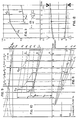
- Figs. 8-12 show how the dimensioning is done in this instance in which the valve serves as constant flow valve in two volumetric flow ranges, that is, in the 50% and 100% ranges.
- Fig. 8 are shown the volumetric flow curves V 1 -V 4 corresponding to four differential pressures as a function of the valve opening 0-11 mm.
- Fig. 10 are plotted, as absolute values, the piston force curves M corresponding to different pressures and the sum curves F s +F w on the same scale.
- the points a, b, c and d are drawn vertical lines to intersection with the curves mentioned, and the points thus obtained are connected by the curves F 50 and M 50 drawn with dotted lines; the same process is repeated for the points e, f and g: curves F 100 and M ioo .
- the ratio AB/AC signifies the ratio of the required piston force to the piston force available, that is the ratio n, with the opening 10 mm.
- the diameter of the control valve cone equivalent to the required opening d 2 ' is found for each position, that is for each valve opening between 4 and 11 mm, by calculation from the formula of n, and they can be plotted to form the surface q, Fig. 12.
- the surface has to be corrected to become the surface q', which is easier to define experimentally with the aid of a straight conical surface.
- the cylinder space carries over-pressure with reference to the ambience. It follows from the universal nature of the formula that the means may also be controlled by vacuum with reference to the ambience. It is then necessary to use instead of the quotient d 2 '/d l ' in the formula its inverse value d l '/d 2 ' if the notation of the apertures with reference to the flow direction is kept unchanged.
- the valve based on cascade control can be governed and controlled in many different ways in addition to those described in connection with Figs. 2-5. Adjustment of the spring 117 of the control valve disc 115 is not considered to be an actual control procedure, but rather a basic adjustment or calibration of the valve. Alternative control means designs are presented in Figs. 13-16.
- the bearing housing 106 of the valve of the invention is provided with an auxiliary cylinder 139, inside of which moves a seat sleeve 136 made to serve as piston and provided with a packing 137'.
- the sleeve is sealed with the packing 138 against the auxiliary cylinder 139.
- the cylinder is at the rear end closed with a cover 140 provided with packing 140'.
- a flange ring 137 On the outer surface of the seat sleeve 136 is provided a flange ring 137 preferably provided with a packing 137', said flange ring resting against the inner surface of the auxiliary cylinder 139, and in the inner space of said auxiliary cylinder, preferably on its opposite ends in the motion direction of the spindle 115, having been provided connectors 141a, 141b for a pneumatic or hydraulic circuit. From this circuit pneumatic or hydraulic pressure p c may be conducted to either side of the flange ring. In this manner, the position of the seat sleeve, and correspondingly the operating range of the valve, can be changed as desired.
- the bearing housing 106 of the valve has in its turn been provided with an auxiliary cylinder, i.e., with a combined spring/pressure cylinder 142 within which moves a seat sleeve 143 formed to be a piston, with its packings 144 and 145'.
- the rear end of the cylinder has been closed with a cover 146 provided with packing 146'.
- a connector 147 for a pneumatic or hydraulic circuit On the first end of the inner space of the auxiliary cylinder 142 has been arranged a connector 147 for a pneumatic or hydraulic circuit, and at the other end of the inner space, between the flange ring 145 of the seat sleeve 143 and the end of the auxiliary cylinder, has been disposed at least one spring 148.
- the seat sleeve can be shifted against the force of the spring 148 by the aid of the pressure p c , using single-circuit pneumatic or hydraulic control instead of the dual circuit control of Fig. 13, and the operating range of the valve can be correspondingly changed in the manner desired.
- the temperature may also be taken into account in the control.
- the means 300 shown in Fig. 15 is intended to control the valve from the outside by means of a tube 212, e.g. electrically by the aid of a relay.
- a control air filter 308 In the lower part of the housing 301 has been placed a control air filter 308 and in the upper part, the d,' nozzle 303 provided with threads, whereunder has been mounted a stop 304 to adjust the opening d 1 '.
- the stop is a metal strip 304, attached by a screw 305, at a distance from the nozzle 303, to the housing 301 of the control means.
- an adjustment screw 306 Between the fixing point of the strip and its free end has been disposed an adjustment screw 306. The smallest gap between the nozzle and the strip can be fixed with the adjustment screw 306.
- the upper part of the housing is provided with plugs 307 for fixing and adjustment.
- an electrically controllable relay 302 which when energized enlarges the opening d,' to a pre-determined value which is dependent on the gap between the relay and the strip.
- the strip 304 may also have another shape and be made of bimetal sheet, whereby it is possible with its aid to account for the temperature of the fluid in the valve control. If needed, the strip may be provided with a ferromagnetic body opposite to the relay. The means 300 may also be used without relay to control the valve merely on the basis of temperature.
- the means 400 shown in Fig. 16 is in other respects like the means 300 of Fig. 15, except that the opening d,' of the d,' nozzle 405 provided with threads is controlled by a bellows 402, mounted on the housing 401 by the aid of a yoke 403 and screws 404.
- the bellows may be enclosed, whereby it reacts only to the temperature of the control air, or it may be open, in which case it is connected to the external pneumatic or hydraulic control circuit by a connector 409.
- the length of the bellows, and at the same time the area of the opening d,' of the nozzle 405, is controllable by pressure.
- the pressure pulse supplied by the control circuit may be based on temperature or another variable.
- the lower part of the housing is provided with a control air filter 407 and the upper part, with plugs 406 for mounting the screws 404.
- the tube 212 connects the control means to the valve 100 as above.
Landscapes
- Engineering & Computer Science (AREA)
- Physics & Mathematics (AREA)
- General Physics & Mathematics (AREA)
- Automation & Control Theory (AREA)
- Fluid Mechanics (AREA)
- Chemical & Material Sciences (AREA)
- Combustion & Propulsion (AREA)
- Mechanical Engineering (AREA)
- General Engineering & Computer Science (AREA)
- Power Engineering (AREA)
- Control Of Fluid Pressure (AREA)
- Flow Control (AREA)
- Paper (AREA)
- Electrical Discharge Machining, Electrochemical Machining, And Combined Machining (AREA)
- External Artificial Organs (AREA)
- Turbine Rotor Nozzle Sealing (AREA)
- Exhaust Gas Treatment By Means Of Catalyst (AREA)
- Feeding And Guiding Record Carriers (AREA)
- Measuring Volume Flow (AREA)
- Sliding Valves (AREA)
Claims (15)
Priority Applications (1)
| Application Number | Priority Date | Filing Date | Title |
|---|---|---|---|
| AT83110878T ATE39998T1 (de) | 1982-11-01 | 1983-10-31 | Einrichtung zur steuerung und/oder messung des durchsatzes eines stroemenden mediums. |
Applications Claiming Priority (2)
| Application Number | Priority Date | Filing Date | Title |
|---|---|---|---|
| FI823730A FI66078C (fi) | 1982-11-01 | 1982-11-01 | Anordning foer reglering och/eller maetning av floedet av flytande medium |
| FI823730 | 1982-11-01 |
Publications (3)
| Publication Number | Publication Date |
|---|---|
| EP0108371A2 EP0108371A2 (de) | 1984-05-16 |
| EP0108371A3 EP0108371A3 (en) | 1985-05-02 |
| EP0108371B1 true EP0108371B1 (de) | 1989-01-11 |
Family
ID=8516234
Family Applications (1)
| Application Number | Title | Priority Date | Filing Date |
|---|---|---|---|
| EP83110878A Expired EP0108371B1 (de) | 1982-11-01 | 1983-10-31 | Einrichtung zur Steuerung und/oder Messung des Durchsatzes eines strömenden Mediums |
Country Status (5)
| Country | Link |
|---|---|
| EP (1) | EP0108371B1 (de) |
| AT (1) | ATE39998T1 (de) |
| DE (1) | DE3378926D1 (de) |
| FI (1) | FI66078C (de) |
| NO (1) | NO153316C (de) |
Families Citing this family (2)
| Publication number | Priority date | Publication date | Assignee | Title |
|---|---|---|---|---|
| DE4443137A1 (de) * | 1994-12-03 | 1996-06-05 | Bosch Gmbh Robert | Verfahren zur Ermittlung der Federkraft einer Schließfeder beim Öffnen eines Ventiles, insbesondere eines Brennstoffeinspritzventiles, und Vorrichtung zur Durchführung des Verfahrens |
| BE1019019A3 (nl) * | 2008-01-14 | 2012-01-10 | Jonghe Marc De | Een watervoorzieningseenheid voor het afleveren van gezuiverd water. |
Family Cites Families (3)
| Publication number | Priority date | Publication date | Assignee | Title |
|---|---|---|---|---|
| US2902915A (en) * | 1954-10-06 | 1959-09-08 | Normalair Ltd | Automatic air flow controllers |
| FR2082292A5 (de) * | 1970-03-10 | 1971-12-10 | Garoche Maurice | |
| FR2319151A1 (fr) * | 1975-07-21 | 1977-02-18 | Powers Regulator Co | Regulateur de debit |
-
1982
- 1982-11-01 FI FI823730A patent/FI66078C/fi not_active IP Right Cessation
-
1983
- 1983-10-31 EP EP83110878A patent/EP0108371B1/de not_active Expired
- 1983-10-31 DE DE8383110878T patent/DE3378926D1/de not_active Expired
- 1983-10-31 AT AT83110878T patent/ATE39998T1/de not_active IP Right Cessation
- 1983-11-01 NO NO833968A patent/NO153316C/no unknown
Also Published As
| Publication number | Publication date |
|---|---|
| NO153316C (no) | 1986-02-19 |
| FI66078B (fi) | 1984-04-30 |
| EP0108371A2 (de) | 1984-05-16 |
| FI66078C (fi) | 1984-08-10 |
| DE3378926D1 (en) | 1989-02-16 |
| EP0108371A3 (en) | 1985-05-02 |
| FI823730A0 (fi) | 1982-11-01 |
| NO153316B (no) | 1985-11-11 |
| NO833968L (no) | 1984-05-02 |
| ATE39998T1 (de) | 1989-01-15 |
Similar Documents
| Publication | Publication Date | Title |
|---|---|---|
| US4532951A (en) | Transducer utilizing electrical and pneumatic signals | |
| JP4851056B2 (ja) | ソレノイド弁 | |
| AU768719B2 (en) | Pressure independent control valve | |
| US4377090A (en) | Through-flow monitor for liquid or gaseous media | |
| US4854156A (en) | Pneumatic surface-following control system | |
| US3598138A (en) | Pressure controller | |
| EP0108371B1 (de) | Einrichtung zur Steuerung und/oder Messung des Durchsatzes eines strömenden Mediums | |
| US3881354A (en) | Fluid velocity responsive instrument | |
| US3363073A (en) | Fluid detection apparatus having magnetic actuating means | |
| EP0508781B1 (de) | Proportionales, elektromagnetisches Stellglied und dasselbe enthaltendes Pumpensystem | |
| US2780230A (en) | Pneumatic control apparatus with follow-up | |
| US2283296A (en) | Valve mechanism | |
| US2543120A (en) | Stabilizer for pneumatic controls | |
| US3765687A (en) | Sealed link for instruments | |
| US2824186A (en) | Fluid pressure actuator | |
| US4511116A (en) | Variable opening pinch sleeve valve | |
| US2888948A (en) | Static pressure regulator | |
| FI80507C (fi) | Transduktor foer omvandlande av elsignal till trycksignal. | |
| US3601138A (en) | Feeler and control device | |
| US2242656A (en) | Measuring instrument | |
| US3137165A (en) | Pneumatic transmitters | |
| US1167343A (en) | Furnace regulation. | |
| US2776567A (en) | Flow responsive device | |
| US3621863A (en) | Valves | |
| JPH0361828A (ja) | 圧力検出器及び流体供給装置 |
Legal Events
| Date | Code | Title | Description |
|---|---|---|---|
| PUAI | Public reference made under article 153(3) epc to a published international application that has entered the european phase |
Free format text: ORIGINAL CODE: 0009012 |
|
| AK | Designated contracting states |
Designated state(s): AT BE DE FR GB NL SE |
|
| PUAL | Search report despatched |
Free format text: ORIGINAL CODE: 0009013 |
|
| AK | Designated contracting states |
Designated state(s): AT BE DE FR GB NL SE |
|
| 17P | Request for examination filed |
Effective date: 19851029 |
|
| 17Q | First examination report despatched |
Effective date: 19860325 |
|
| GRAA | (expected) grant |
Free format text: ORIGINAL CODE: 0009210 |
|
| AK | Designated contracting states |
Kind code of ref document: B1 Designated state(s): AT BE DE FR GB NL SE |
|
| REF | Corresponds to: |
Ref document number: 39998 Country of ref document: AT Date of ref document: 19890115 Kind code of ref document: T |
|
| REF | Corresponds to: |
Ref document number: 3378926 Country of ref document: DE Date of ref document: 19890216 |
|
| ET | Fr: translation filed | ||
| PLBE | No opposition filed within time limit |
Free format text: ORIGINAL CODE: 0009261 |
|
| STAA | Information on the status of an ep patent application or granted ep patent |
Free format text: STATUS: NO OPPOSITION FILED WITHIN TIME LIMIT |
|
| 26N | No opposition filed | ||
| EAL | Se: european patent in force in sweden |
Ref document number: 83110878.2 |
|
| PGFP | Annual fee paid to national office [announced via postgrant information from national office to epo] |
Ref country code: FR Payment date: 19970307 Year of fee payment: 14 |
|
| PGFP | Annual fee paid to national office [announced via postgrant information from national office to epo] |
Ref country code: BE Payment date: 19970313 Year of fee payment: 14 Ref country code: AT Payment date: 19970313 Year of fee payment: 14 |
|
| PGFP | Annual fee paid to national office [announced via postgrant information from national office to epo] |
Ref country code: SE Payment date: 19970314 Year of fee payment: 14 |
|
| PGFP | Annual fee paid to national office [announced via postgrant information from national office to epo] |
Ref country code: GB Payment date: 19970319 Year of fee payment: 14 |
|
| PGFP | Annual fee paid to national office [announced via postgrant information from national office to epo] |
Ref country code: DE Payment date: 19970321 Year of fee payment: 14 |
|
| PGFP | Annual fee paid to national office [announced via postgrant information from national office to epo] |
Ref country code: NL Payment date: 19970327 Year of fee payment: 14 |
|
| PG25 | Lapsed in a contracting state [announced via postgrant information from national office to epo] |
Ref country code: GB Free format text: LAPSE BECAUSE OF NON-PAYMENT OF DUE FEES Effective date: 19971031 Ref country code: FR Free format text: THE PATENT HAS BEEN ANNULLED BY A DECISION OF A NATIONAL AUTHORITY Effective date: 19971031 Ref country code: BE Free format text: LAPSE BECAUSE OF NON-PAYMENT OF DUE FEES Effective date: 19971031 Ref country code: AT Free format text: LAPSE BECAUSE OF NON-PAYMENT OF DUE FEES Effective date: 19971031 |
|
| PG25 | Lapsed in a contracting state [announced via postgrant information from national office to epo] |
Ref country code: SE Free format text: LAPSE BECAUSE OF NON-PAYMENT OF DUE FEES Effective date: 19971101 |
|
| BERE | Be: lapsed |
Owner name: NISKANEN ERKKI JOHANNES Effective date: 19971031 |
|
| PG25 | Lapsed in a contracting state [announced via postgrant information from national office to epo] |
Ref country code: NL Free format text: LAPSE BECAUSE OF NON-PAYMENT OF DUE FEES Effective date: 19980501 |
|
| GBPC | Gb: european patent ceased through non-payment of renewal fee |
Effective date: 19971031 |
|
| NLV4 | Nl: lapsed or anulled due to non-payment of the annual fee |
Effective date: 19980501 |
|
| PG25 | Lapsed in a contracting state [announced via postgrant information from national office to epo] |
Ref country code: DE Free format text: LAPSE BECAUSE OF NON-PAYMENT OF DUE FEES Effective date: 19980701 |
|
| EUG | Se: european patent has lapsed |
Ref document number: 83110878.2 |
|
| REG | Reference to a national code |
Ref country code: FR Ref legal event code: ST |