EP0108319A2 - Vorrichtung zum Eintragen von dosierten Mengen von körnigen Feststoffen in ein pneumatisches Treibfluidum und Anwendung zum Einbringen fester Brennstoffe in einen Schachtofen - Google Patents
Vorrichtung zum Eintragen von dosierten Mengen von körnigen Feststoffen in ein pneumatisches Treibfluidum und Anwendung zum Einbringen fester Brennstoffe in einen Schachtofen Download PDFInfo
- Publication number
- EP0108319A2 EP0108319A2 EP83110587A EP83110587A EP0108319A2 EP 0108319 A2 EP0108319 A2 EP 0108319A2 EP 83110587 A EP83110587 A EP 83110587A EP 83110587 A EP83110587 A EP 83110587A EP 0108319 A2 EP0108319 A2 EP 0108319A2
- Authority
- EP
- European Patent Office
- Prior art keywords
- housing
- sockets
- sleeve
- movable
- slots
- Prior art date
- Legal status (The legal status is an assumption and is not a legal conclusion. Google has not performed a legal analysis and makes no representation as to the accuracy of the status listed.)
- Granted
Links
- 239000000463 material Substances 0.000 title claims abstract description 25
- 239000012530 fluid Substances 0.000 title claims abstract description 16
- 239000004449 solid propellant Substances 0.000 title claims description 3
- 238000002347 injection Methods 0.000 title description 3
- 239000007924 injection Substances 0.000 title description 3
- 239000003380 propellant Substances 0.000 claims abstract 3
- 230000009471 action Effects 0.000 claims description 6
- 238000009434 installation Methods 0.000 claims description 2
- WFKWXMTUELFFGS-UHFFFAOYSA-N tungsten Chemical compound [W] WFKWXMTUELFFGS-UHFFFAOYSA-N 0.000 claims description 2
- 239000010937 tungsten Substances 0.000 claims description 2
- 229910052721 tungsten Inorganic materials 0.000 claims description 2
- 239000002245 particle Substances 0.000 description 8
- 230000004048 modification Effects 0.000 description 5
- 238000012986 modification Methods 0.000 description 5
- 206010010904 Convulsion Diseases 0.000 description 4
- 230000008901 benefit Effects 0.000 description 3
- 230000015572 biosynthetic process Effects 0.000 description 3
- 239000000843 powder Substances 0.000 description 3
- 239000010419 fine particle Substances 0.000 description 2
- 238000007789 sealing Methods 0.000 description 2
- 229910000906 Bronze Inorganic materials 0.000 description 1
- 239000004809 Teflon Substances 0.000 description 1
- 229920006362 Teflon® Polymers 0.000 description 1
- 230000004323 axial length Effects 0.000 description 1
- 230000001413 cellular effect Effects 0.000 description 1
- 230000008859 change Effects 0.000 description 1
- 210000000078 claw Anatomy 0.000 description 1
- 239000003245 coal Substances 0.000 description 1
- 230000000295 complement effect Effects 0.000 description 1
- 229910003460 diamond Inorganic materials 0.000 description 1
- 239000010432 diamond Substances 0.000 description 1
- 239000003077 lignite Substances 0.000 description 1
- 230000014759 maintenance of location Effects 0.000 description 1
- 230000000873 masking effect Effects 0.000 description 1
- 230000000149 penetrating effect Effects 0.000 description 1
- 230000002028 premature Effects 0.000 description 1
Images




Classifications
-
- B—PERFORMING OPERATIONS; TRANSPORTING
- B65—CONVEYING; PACKING; STORING; HANDLING THIN OR FILAMENTARY MATERIAL
- B65G—TRANSPORT OR STORAGE DEVICES, e.g. CONVEYORS FOR LOADING OR TIPPING, SHOP CONVEYOR SYSTEMS OR PNEUMATIC TUBE CONVEYORS
- B65G53/00—Conveying materials in bulk through troughs, pipes or tubes by floating the materials or by flow of gas, liquid or foam
- B65G53/34—Details
- B65G53/40—Feeding or discharging devices
- B65G53/46—Gates or sluices, e.g. rotary wheels
-
- C—CHEMISTRY; METALLURGY
- C21—METALLURGY OF IRON
- C21B—MANUFACTURE OF IRON OR STEEL
- C21B5/00—Making pig-iron in the blast furnace
- C21B5/001—Injecting additional fuel or reducing agents
- C21B5/003—Injection of pulverulent coal
-
- F—MECHANICAL ENGINEERING; LIGHTING; HEATING; WEAPONS; BLASTING
- F23—COMBUSTION APPARATUS; COMBUSTION PROCESSES
- F23K—FEEDING FUEL TO COMBUSTION APPARATUS
- F23K3/00—Feeding or distributing of lump or pulverulent fuel to combustion apparatus
- F23K3/02—Pneumatic feeding arrangements, i.e. by air blast
-
- G—PHYSICS
- G01—MEASURING; TESTING
- G01F—MEASURING VOLUME, VOLUME FLOW, MASS FLOW OR LIQUID LEVEL; METERING BY VOLUME
- G01F11/00—Apparatus requiring external operation adapted at each repeated and identical operation to measure and separate a predetermined volume of fluid or fluent solid material from a supply or container, without regard to weight, and to deliver it
- G01F11/10—Apparatus requiring external operation adapted at each repeated and identical operation to measure and separate a predetermined volume of fluid or fluent solid material from a supply or container, without regard to weight, and to deliver it with measuring chambers moved during operation
- G01F11/12—Apparatus requiring external operation adapted at each repeated and identical operation to measure and separate a predetermined volume of fluid or fluent solid material from a supply or container, without regard to weight, and to deliver it with measuring chambers moved during operation of the valve type, i.e. the separating being effected by fluid-tight or powder-tight movements
- G01F11/20—Apparatus requiring external operation adapted at each repeated and identical operation to measure and separate a predetermined volume of fluid or fluent solid material from a supply or container, without regard to weight, and to deliver it with measuring chambers moved during operation of the valve type, i.e. the separating being effected by fluid-tight or powder-tight movements wherein the measuring chamber rotates or oscillates
- G01F11/24—Apparatus requiring external operation adapted at each repeated and identical operation to measure and separate a predetermined volume of fluid or fluent solid material from a supply or container, without regard to weight, and to deliver it with measuring chambers moved during operation of the valve type, i.e. the separating being effected by fluid-tight or powder-tight movements wherein the measuring chamber rotates or oscillates for fluent solid material
Definitions
- the present invention relates to a device for introducing metered quantities of pulverulent materials into a pneumatic propulsion fluid and, as a preferred application, injecting solid fuels into a shaft furnace.
- European patent application No. 0043606 describes an installation for pneumatically transporting pulverulent materials and, more particularly, coal powder or lignite for injection into a tank furnace.
- the formation of the pneumatic current that is to say the introduction of the pulverulent particles into a stream of pressurized air for the propulsion of these pulverulent particles is carried out by means of an airlock with an alveolar rotor, known per se.
- an alveolar rotor known per se. It is, in this case, a device essentially consisting of a cylindrical rotor provided on its periphery with a certain number of pallets defining a corresponding number of cells. This rotor turns in a sealed manner inside a housing and the material supplied from above is driven by the cells downward in a stream of pressurized air serving as propulsion fluid. This propelling air entrains the materials as it is delivered by the cells.
- the object of the present invention is to provide a new device for introducing metered quantities of pulverulent materials into a pneumatic propulsion fluid which does not have the drawbacks described above.
- the device proposed by the invention is essentially characterized by a housing traversed, at least in part, axially by a pressurized fluid and comprising a lateral opening in communication with a reservoir of pulverulent materials, in which a higher pressure prevails.
- this housing containing two coaxial sockets, the one of which is inside is provided with an axial bore for the passage of the propulsion fluid and one of which, at least, is movable around its longitudinal axis and is connected, for this purpose, to a suitable driving device, each of the sockets being provided with a slot at the lateral opening of the housing, so that these slots can more or less overlap or hide mutually by rotation of the movable sleeve and thus define a more or less large passage between the pulverulent material reservoir and the propulsion fluid passing through the inner sleeve.
- the inner sleeve is rotatable, while the outer sleeve is secured to the fixed housing, while in a second embodiment the inner sleeve is fixed and the outer sleeve is movable.
- This latter embodiment has the advantage, compared with the first, of reducing the risks of formation of a bridge at the level of the lateral opening.
- the slots in the two sockets are either identical in shape or complementary in shape.
- the length of the two sockets corresponds substantially to the diameter of the lateral opening of the housing, while an annular friction ring is provided between the housing and the front annular surface of the movable socket.
- movable sleeve being subjected to the axial force of a spring whose action keeps this sleeve in contact with this ring.
- the tension of the spring acting on the movable sleeve is preferably adjustable.
- the outer diameter of the outer sleeve is preferably less than the inner diameter of the housing, in order to define a free annular space between the outer sleeve and the case in order to reduce the risk of seizing.
- the metering device shown in Figure 1 consists of a cylindrical housing 10 whose two bases are closed respectively by a fixing flange tion 12 and a front plate 14. Inside the housing 10 are two coaxial sockets 16 and 18. In the embodiment shown, the socket 18 is fixed and integral with the front plate 14, while the socket 16 can rotate around the longitudinal axis O as described in more detail below.
- the inner sleeve 16 has an axial bore 20 communicating with a pneumatic conveying line 22.
- the housing 10 comprises two lateral tubes 24 and 26; the tubing 24 communicating with a reservoir of pulverulent materials, while the tubing 26 is connected to a source of pressurized air to drive the pulverulent material through the pipe 22.
- the tubing 26 communicates through an annular chamber 28 directly with the axial bore 20 of the inner bush 16.
- the two bushes 16 and 18 each have, at the tubing 24 for admitting the pulverulent material, a lateral slot 30 respectively 32, which, depending on the angular position of the movable sleeve 16, define a more or less large passage between this tube 24 and the axial bore 20.
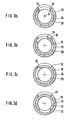
- Figures 3a to 3d which show cross sections at the slots 30 and 32 show different angular positions of the inner movable bush 16. In the position according to FIG. 3a, the bush 16 is rotated so that the slots 30 and 32 are perfectly aligned with each other, thus defining a passage with maximum opening between the tubing 24 and the bore 20. Starting from the position according to FIG. 3a, a rotation of the sleeve 16 progressively reduces the section of the opening between the pipe 24 and the bore 20, as in the show Figures 3b and 3c, the latter corresponding to the minimum opening.
- Figure 3d shows the complete closure of the
- a drive shaft 34 arranged in the extension of the bush 16 on the side opposite to the discharge pipe 22.
- This shaft 34 is housed in the housing 10 by means of a bearing 36 and a sealing ring 38 preventing leaks of the compressed air.
- This drive shaft 34 is made integral in rotation with the movable bush 16, for example by means of two claws 40 diametrically opposite and penetrating into corresponding front grooves of the bush 16.
- This drive shaft 34 is connected by an intermediate piece 42 to a stepping electric motor.
- a motor was used which caused a rotation of 0.36 0 per electric pulse at a speed of 1 to 2 revolutions per minute.
- the pressurized air passes through, from the tubing 26, the annular chamber 28, the internal bore 20 in the direction of the pneumatic line 22, driving in passing the pulverulent material introduced through the calibrated opening defined by the slots 30 and 32 under the action of a pressure difference existing between the powdery material reservoir not shown and the air pressure in the bore 20.
- the progress made by the device according to the invention essentially consists in the fact that very few parts are in motion. While in the airlock rotors the change of flow rate is effected by modification of the speed of rotation of the airlock, a modification of the flow rate in the proposed device is achievable by means of a slight modification of the angular position of the movable sleeve. It is even important to emphasize that, at constant flow, no part is in motion.
- the inner bush 16 ' is fixed and integral with the front plate 14 while the outer bush 18' is movable and connected for this purpose to the shaft drive 34 in the same manner as in the embodiment of Figure 1.
- the two slots 30 'and 32' provided in the sockets 16 'and 18' also define the section of the passage for the powdery material. If the operation of the device according to Figure 2 is absolutely identical to that of the device of Figure 1, it may, however, have some advantage in that it is the outer sleeve which is movable instead of the inner sleeve.
- the pulverulent material being brought under pressure through the tubing 24 could tend to form a bridge around the slot 32 or 32 'of the socket 18 or 18' and if it is this socket 18 'which is mobile, the risk of forming such a bridge is, of course, considerably reduced.
- Figures 4, 5, 6 and 7 show different forms of slots in different positions as seen through the opening 24 and developed in plan.
- these are simple elongated slots 30 and 32 which, in the position according to FIG. 4a, overlap only very slightly, thus defining a minimum circular cross-section of the material.
- a rotation of the movable sleeve increases the section of the opening as shown in Figure 4b, the section of this opening becoming maximum in the position of Figure 4c where the two slots 30 and 32 are in alignment position.
- FIGS. 5, 6 and 7 positions corresponding to the positions of FIGS. 4a, 4b and 4c have been adopted, with, however, variants of the shapes of the slots.
- the slots of the series of Figures 5 are wider than those of the series of Figures 4 which allows a higher flow.
- the particular forms of the series in FIGS. 6 and 7 have the particularity that the modification of the section of the opening is made both in length and in width. This has the advantage that the variation of the section is faster or that the movable sleeve turns less for the same modification. Changing the cross-section can also help reduce the risk of bridge formation.
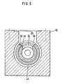
- Figures 8 and 9 show an advantageous variant of the embodiment of Figures 1 and 2.
- the two metering sleeves 44 and 46 corresponding to the metering sleeves described above.
- the sleeve 44 is fixed and integral with the housing 10, while the sleeve 46 is movable around the longitudinal axis O and forms the front end of a cylindrical body 48 which can rotate and slide longitudinally in a bore of the housing 10.
- the pressurized air is admitted through an annular chamber 50 of this body 48 and the hollow central part of the latter in a mixing chamber 52 formed inside the inner sleeve 44 and extending through the axis of the housing 10 to a pneumatic transport pipe not shown.
- the two sockets 44 and 46 respectively have metering slots 54, 56 (see also FIG. 9), the operation of which is controlled by rotation of the movable socket around the axis O, already described with reference to the preceding figures.
- the powdery powder can penetrate, at most, between the two sockets but, since, on the one hand, this surface is very reduced and, on the other hand, it is possible to leave some play between these two sockets, the risks of seizing are very reduced.
- a certain clearance is, in fact, possible between the two sockets, since the seal is ensured, according to another characteristic of the invention, by a friction ring 58, for example made of teflon and bronze alloy, arranged , in the embodiment shown, around the fixed bush 44 between the housing 10 and the end of the mobile bush 46. This mobile bush 46 is held under the action of a spring against the ring 58.
- the outer diameter of the outer sleeve 46 is less than the diameter of the bore in the housing 10 so as to define a free annular space 45 in which there is no risk of seizure.
- a spring 60 for example of the "Belleville spring” type wedged between the body 48 and a sleeve 62.
- This sleeve is fixed in the axial direction but can rotate around the axis O by virtue of its mounting in bearings 64 and sealing rings 66, 76.
- the action of the spring 60 is exerted, consequently, on the body 48 and the sleeve 46 in the direction of the friction ring 58.
- the independence of the longitudinal movement of the body 48 relative to the sleeve 62 and the dependence of the angular movements between these two parts can be ensured by any known means, for example, as shown in the figure using a key 68.
- the rotation of the sleeve 62 for example by means of a handle as symbolized by the reference 70 causes the rotation of the movable sleeve 46 and more or less masking of the slots 54 and 56 as explained with reference to the previous figures.
- the pressure of the spring 60 is adjustable, for example by means of an adjustment rod 72 and a fixing nut 74.
- the opening 24 can be oblong instead of being circular.
- the pressurized air is also admitted through channels or interstices 78 in the chamber containing the spring 60.
Landscapes
- Engineering & Computer Science (AREA)
- Chemical & Material Sciences (AREA)
- Mechanical Engineering (AREA)
- Manufacturing & Machinery (AREA)
- Metallurgy (AREA)
- Fluid Mechanics (AREA)
- Combustion & Propulsion (AREA)
- General Engineering & Computer Science (AREA)
- Physics & Mathematics (AREA)
- Materials Engineering (AREA)
- General Physics & Mathematics (AREA)
- Organic Chemistry (AREA)
- Filling Or Emptying Of Bunkers, Hoppers, And Tanks (AREA)
- Nozzles (AREA)
- Furnace Charging Or Discharging (AREA)
- Crucibles And Fluidized-Bed Furnaces (AREA)
- Feeding, Discharge, Calcimining, Fusing, And Gas-Generation Devices (AREA)
Priority Applications (1)
| Application Number | Priority Date | Filing Date | Title |
|---|---|---|---|
| AT83110587T ATE32525T1 (de) | 1982-11-10 | 1983-10-24 | Vorrichtung zum eintragen von dosierten mengen von koernigen feststoffen in ein pneumatisches treibfluidum und anwendung zum einbringen fester brennstoffe in einen schachtofen. |
Applications Claiming Priority (4)
| Application Number | Priority Date | Filing Date | Title |
|---|---|---|---|
| LU84462 | 1982-11-10 | ||
| LU84462A LU84462A1 (fr) | 1982-11-10 | 1982-11-10 | Dispositif d'introduction de quantites dosees de matieres pulverulentes dans un fluide de propulsion pneumatique et application a l'injection de combustibles solides dans un four a cuve |
| LU84812A LU84812A7 (fr) | 1983-05-19 | 1983-05-19 | Dispositif d'introduction de quantites dosees de matieres pulverulentes dans un fluide de propulsion pneumatique et application a l'injection de combustibles solides dans un four a cuve |
| LU84812 | 1983-05-19 |
Publications (3)
| Publication Number | Publication Date |
|---|---|
| EP0108319A2 true EP0108319A2 (de) | 1984-05-16 |
| EP0108319A3 EP0108319A3 (en) | 1985-11-21 |
| EP0108319B1 EP0108319B1 (de) | 1988-02-17 |
Family
ID=26640293
Family Applications (1)
| Application Number | Title | Priority Date | Filing Date |
|---|---|---|---|
| EP83110587A Expired EP0108319B1 (de) | 1982-11-10 | 1983-10-24 | Vorrichtung zum Eintragen von dosierten Mengen von körnigen Feststoffen in ein pneumatisches Treibfluidum und Anwendung zum Einbringen fester Brennstoffe in einen Schachtofen |
Country Status (9)
| Country | Link |
|---|---|
| US (1) | US4606677A (de) |
| EP (1) | EP0108319B1 (de) |
| AR (1) | AR230884A1 (de) |
| AU (1) | AU557972B2 (de) |
| BR (1) | BR8306315A (de) |
| CA (1) | CA1225418A (de) |
| DE (1) | DE3375698D1 (de) |
| ES (1) | ES526192A0 (de) |
| PL (1) | PL137025B1 (de) |
Cited By (8)
| Publication number | Priority date | Publication date | Assignee | Title |
|---|---|---|---|---|
| EP0126917A3 (en) * | 1983-04-28 | 1985-05-02 | Paul Wurth S.A. | Device for introducing dosed quantities of powdery materials into a pneumatic fluid, and its application to a distributing bin |
| EP0196425A3 (en) * | 1985-03-06 | 1987-04-29 | Klockner Cra Technologie Gmbh | Flow-regulating valve for granular solids |
| EP0158308B1 (de) * | 1984-04-11 | 1987-07-15 | Paul Wurth S.A. | Vorrichtung zum Einführen dosierter Mengen von pulverisiertem Material in ein pneumatisch vorbewegtes Fluidbett |
| EP0158309B1 (de) * | 1984-04-11 | 1987-07-15 | Paul Wurth S.A. | Vorrichtung zum Einführen dosierter Mengen von pulverisiertem Material in ein pneumatisch vorbewegtes Fluidbett |
| EP0233624A3 (de) * | 1986-02-19 | 1989-01-04 | Paul Wurth S.A. | Dosiereinrichtung für feinkörnige Feststoffe und Anwendung für ein dosiertes Einblasen von festen Brennstoffen in einen Schachtofen |
| EP0289965A3 (de) * | 1987-05-07 | 1989-06-28 | Paul Wurth S.A. | Vorrichtung zur Änderung der Querschnittsfläche einer pneumatischen Förderleitung und Anwendung zur Einspritzung von festen Brennstoffen in einen Schachtofen |
| CN105712084A (zh) * | 2016-02-01 | 2016-06-29 | 北京理工大学 | 一种气体压力驱动式均匀供粉装置和方法 |
| CN111809033A (zh) * | 2020-07-22 | 2020-10-23 | 赣州市合安科技有限公司 | 一种进出料方便的井式回火炉 |
Families Citing this family (2)
| Publication number | Priority date | Publication date | Assignee | Title |
|---|---|---|---|---|
| DE3436624A1 (de) * | 1984-10-05 | 1986-04-10 | Norddeutsche Affinerie AG, 2000 Hamburg | Vorrichtung zur erzeugung zuendfaehiger feststoff/gas-suspensionen |
| US5211751A (en) * | 1992-02-28 | 1993-05-18 | W.R. Grace & Co.-Conn. | Hydraulic cement set-accelerating admixtures incorporating amino acid derivatives |
Family Cites Families (9)
| Publication number | Priority date | Publication date | Assignee | Title |
|---|---|---|---|---|
| US2731302A (en) * | 1953-05-11 | 1956-01-17 | Upham Charles Roland | Air switch and ported control head for powdered iron dispenser |
| US3006512A (en) * | 1958-07-16 | 1961-10-31 | Keathley | Material dispensing machine |
| GB1094112A (en) * | 1964-10-14 | 1967-12-06 | Tills Engineering Co Ltd | Transporting and dispensing installation for granular and pulverulent material |
| US3527503A (en) * | 1968-08-05 | 1970-09-08 | Pullman Inc | Pneumatic outlet assembly for hoppers |
| SU371147A1 (ru) * | 1970-06-16 | 1973-02-22 | Н. И. Чебыкин, А. Н. Стриганов , И. Б. Левицкий Производственно техническое объединение Уралэнергоцветмет | Питатель всасывающей пневмотранспортной |
| US3840158A (en) * | 1972-10-17 | 1974-10-08 | Nordson Corp | Modular applicator system |
| DE2552594B2 (de) * | 1975-11-24 | 1977-09-22 | Ingenieurgesellschaft Industriebau mbH, 2000 Hamburg | Vorrichtung zum dosieren und absperren von staubfoermigen und rieselfaehigen schuettguetern |
| GB1493525A (en) * | 1976-04-13 | 1977-11-30 | Lister & Co Ltd R | Agricultural broadcaster |
| JPS5942045B2 (ja) * | 1980-05-22 | 1984-10-12 | ドネツキイ ナウチノ−イスレドバテルスキイ インステイチユ−トチエルノイ メタルルギイ | 微粉砕石炭を高炉炉床に供給するための通気供給器 |
-
1983
- 1983-09-28 AU AU19661/83A patent/AU557972B2/en not_active Ceased
- 1983-10-01 ES ES526192A patent/ES526192A0/es active Granted
- 1983-10-11 AR AR294508A patent/AR230884A1/es active
- 1983-10-24 EP EP83110587A patent/EP0108319B1/de not_active Expired
- 1983-10-24 DE DE8383110587T patent/DE3375698D1/de not_active Expired
- 1983-10-28 CA CA000439963A patent/CA1225418A/en not_active Expired
- 1983-11-10 BR BR8306315A patent/BR8306315A/pt not_active IP Right Cessation
- 1983-11-10 PL PL1983244498A patent/PL137025B1/pl unknown
- 1983-11-10 US US06/550,565 patent/US4606677A/en not_active Expired - Fee Related
Cited By (8)
| Publication number | Priority date | Publication date | Assignee | Title |
|---|---|---|---|---|
| EP0126917A3 (en) * | 1983-04-28 | 1985-05-02 | Paul Wurth S.A. | Device for introducing dosed quantities of powdery materials into a pneumatic fluid, and its application to a distributing bin |
| EP0158308B1 (de) * | 1984-04-11 | 1987-07-15 | Paul Wurth S.A. | Vorrichtung zum Einführen dosierter Mengen von pulverisiertem Material in ein pneumatisch vorbewegtes Fluidbett |
| EP0158309B1 (de) * | 1984-04-11 | 1987-07-15 | Paul Wurth S.A. | Vorrichtung zum Einführen dosierter Mengen von pulverisiertem Material in ein pneumatisch vorbewegtes Fluidbett |
| EP0196425A3 (en) * | 1985-03-06 | 1987-04-29 | Klockner Cra Technologie Gmbh | Flow-regulating valve for granular solids |
| EP0233624A3 (de) * | 1986-02-19 | 1989-01-04 | Paul Wurth S.A. | Dosiereinrichtung für feinkörnige Feststoffe und Anwendung für ein dosiertes Einblasen von festen Brennstoffen in einen Schachtofen |
| EP0289965A3 (de) * | 1987-05-07 | 1989-06-28 | Paul Wurth S.A. | Vorrichtung zur Änderung der Querschnittsfläche einer pneumatischen Förderleitung und Anwendung zur Einspritzung von festen Brennstoffen in einen Schachtofen |
| CN105712084A (zh) * | 2016-02-01 | 2016-06-29 | 北京理工大学 | 一种气体压力驱动式均匀供粉装置和方法 |
| CN111809033A (zh) * | 2020-07-22 | 2020-10-23 | 赣州市合安科技有限公司 | 一种进出料方便的井式回火炉 |
Also Published As
| Publication number | Publication date |
|---|---|
| AR230884A1 (es) | 1984-07-31 |
| AU557972B2 (en) | 1987-01-15 |
| ES8406696A1 (es) | 1984-08-16 |
| AU1966183A (en) | 1984-05-17 |
| CA1225418A (en) | 1987-08-11 |
| DE3375698D1 (en) | 1988-03-24 |
| EP0108319B1 (de) | 1988-02-17 |
| US4606677A (en) | 1986-08-19 |
| PL137025B1 (en) | 1986-04-30 |
| ES526192A0 (es) | 1984-08-16 |
| PL244498A1 (en) | 1984-07-16 |
| BR8306315A (pt) | 1984-06-19 |
| EP0108319A3 (en) | 1985-11-21 |
Similar Documents
| Publication | Publication Date | Title |
|---|---|---|
| EP0108319B1 (de) | Vorrichtung zum Eintragen von dosierten Mengen von körnigen Feststoffen in ein pneumatisches Treibfluidum und Anwendung zum Einbringen fester Brennstoffe in einen Schachtofen | |
| EP1047892A1 (de) | Ventil zur regelung der durchflussmenge | |
| FR2663091A1 (fr) | Dispositif de commande par arbre a came et moyens transmetteurs d'efforts a galet. | |
| EP0505297B1 (de) | Hydraulischer Zylinder mit Vorrichtung zum Anzeigen der Kolbenstellung | |
| FR2967748A1 (fr) | Systeme d'etancheite a joint annulaire a brosse | |
| EP0300858A1 (de) | Rotationsriemenspanner für Riemengetriebe | |
| FR2649163A1 (fr) | Machine hydrostatique a deplacement volumetrique | |
| EP1939457A1 (de) | Pumpe mit elastischer Vorrichtung auf einem Lager | |
| EP0158309B1 (de) | Vorrichtung zum Einführen dosierter Mengen von pulverisiertem Material in ein pneumatisch vorbewegtes Fluidbett | |
| LU84462A1 (fr) | Dispositif d'introduction de quantites dosees de matieres pulverulentes dans un fluide de propulsion pneumatique et application a l'injection de combustibles solides dans un four a cuve | |
| EP0158308B1 (de) | Vorrichtung zum Einführen dosierter Mengen von pulverisiertem Material in ein pneumatisch vorbewegtes Fluidbett | |
| EP0509242A1 (de) | Vorrichtung zur gleichmässigen Verteilung von pulverförmigen Materialien | |
| FR2961566A1 (fr) | Actionneur a verin d'un organe mobile dans une turbomachine | |
| EP1620650B1 (de) | Druckmittelverteiler mit doppelführung | |
| EP0021950B1 (de) | Servolenkung für Kraftfahrzeug | |
| FR2681107A1 (fr) | Pompe pour liquides visqueux. | |
| FR3099222A1 (fr) | Vanne papillon perfectionnée pour le transport de fluide sous haute pression ou sous extrême pression | |
| EP0054979B1 (de) | Variator mit stufenloser Regelung der Geschwindigkeit | |
| FR3001498A1 (fr) | Partie fixe de recepteur de turbomachine comprenant un ensemble de maintien en position de servitudes a l'interieur d'un arbre creux fixe | |
| LU84812A7 (fr) | Dispositif d'introduction de quantites dosees de matieres pulverulentes dans un fluide de propulsion pneumatique et application a l'injection de combustibles solides dans un four a cuve | |
| EP3019278B1 (de) | Sprühdüse zum elektrostatischen spritzen eines beschichtungsproduktes und anlage zum spritzen | |
| WO2011098736A2 (fr) | Turbopropulseur muni d'un dispositif d'orientation de pales | |
| EP4497647A1 (de) | Antriebslager und motor mit einem solchen lager | |
| FR3046406A1 (fr) | Dispositif de commande de l'orientation des pales de soufflante d'un turbopropulseur | |
| EP0233624A2 (de) | Dosiereinrichtung für feinkörnige Feststoffe und Anwendung für ein dosiertes Einblasen von festen Brennstoffen in einen Schachtofen |
Legal Events
| Date | Code | Title | Description |
|---|---|---|---|
| PUAI | Public reference made under article 153(3) epc to a published international application that has entered the european phase |
Free format text: ORIGINAL CODE: 0009012 |
|
| AK | Designated contracting states |
Designated state(s): AT BE DE FR GB IT NL SE |
|
| 17P | Request for examination filed |
Effective date: 19840925 |
|
| PUAL | Search report despatched |
Free format text: ORIGINAL CODE: 0009013 |
|
| AK | Designated contracting states |
Designated state(s): AT BE DE FR GB IT NL SE |
|
| 17Q | First examination report despatched |
Effective date: 19861022 |
|
| GRAA | (expected) grant |
Free format text: ORIGINAL CODE: 0009210 |
|
| AK | Designated contracting states |
Kind code of ref document: B1 Designated state(s): AT BE DE FR GB IT NL SE |
|
| REF | Corresponds to: |
Ref document number: 32525 Country of ref document: AT Date of ref document: 19880315 Kind code of ref document: T |
|
| REF | Corresponds to: |
Ref document number: 3375698 Country of ref document: DE Date of ref document: 19880324 |
|
| GBT | Gb: translation of ep patent filed (gb section 77(6)(a)/1977) | ||
| ITF | It: translation for a ep patent filed | ||
| PLBE | No opposition filed within time limit |
Free format text: ORIGINAL CODE: 0009261 |
|
| STAA | Information on the status of an ep patent application or granted ep patent |
Free format text: STATUS: NO OPPOSITION FILED WITHIN TIME LIMIT |
|
| 26N | No opposition filed | ||
| PGFP | Annual fee paid to national office [announced via postgrant information from national office to epo] |
Ref country code: FR Payment date: 19890913 Year of fee payment: 7 |
|
| PGFP | Annual fee paid to national office [announced via postgrant information from national office to epo] |
Ref country code: SE Payment date: 19890919 Year of fee payment: 7 |
|
| PGFP | Annual fee paid to national office [announced via postgrant information from national office to epo] |
Ref country code: AT Payment date: 19890920 Year of fee payment: 7 |
|
| PGFP | Annual fee paid to national office [announced via postgrant information from national office to epo] |
Ref country code: DE Payment date: 19890921 Year of fee payment: 7 |
|
| PGFP | Annual fee paid to national office [announced via postgrant information from national office to epo] |
Ref country code: BE Payment date: 19890925 Year of fee payment: 7 |
|
| PGFP | Annual fee paid to national office [announced via postgrant information from national office to epo] |
Ref country code: GB Payment date: 19890930 Year of fee payment: 7 |
|
| ITTA | It: last paid annual fee | ||
| PGFP | Annual fee paid to national office [announced via postgrant information from national office to epo] |
Ref country code: NL Payment date: 19891031 Year of fee payment: 7 |
|
| PG25 | Lapsed in a contracting state [announced via postgrant information from national office to epo] |
Ref country code: GB Effective date: 19901024 Ref country code: AT Effective date: 19901024 |
|
| PG25 | Lapsed in a contracting state [announced via postgrant information from national office to epo] |
Ref country code: SE Effective date: 19901025 |
|
| PG25 | Lapsed in a contracting state [announced via postgrant information from national office to epo] |
Ref country code: BE Effective date: 19901031 |
|
| BERE | Be: lapsed |
Owner name: S.A. PAUL WURTH Effective date: 19901031 |
|
| PG25 | Lapsed in a contracting state [announced via postgrant information from national office to epo] |
Ref country code: NL Effective date: 19910501 |
|
| NLV4 | Nl: lapsed or anulled due to non-payment of the annual fee | ||
| GBPC | Gb: european patent ceased through non-payment of renewal fee | ||
| PG25 | Lapsed in a contracting state [announced via postgrant information from national office to epo] |
Ref country code: FR Effective date: 19910628 |
|
| PG25 | Lapsed in a contracting state [announced via postgrant information from national office to epo] |
Ref country code: DE Effective date: 19910702 |
|
| REG | Reference to a national code |
Ref country code: FR Ref legal event code: ST |
|
| EUG | Se: european patent has lapsed |
Ref document number: 83110587.9 Effective date: 19910603 |