EP0108148B1 - A foundry pouring station table - Google Patents
A foundry pouring station table Download PDFInfo
- Publication number
- EP0108148B1 EP0108148B1 EP82901309A EP82901309A EP0108148B1 EP 0108148 B1 EP0108148 B1 EP 0108148B1 EP 82901309 A EP82901309 A EP 82901309A EP 82901309 A EP82901309 A EP 82901309A EP 0108148 B1 EP0108148 B1 EP 0108148B1
- Authority
- EP
- European Patent Office
- Prior art keywords
- movable
- sand mold
- liners
- stationary
- frame
- Prior art date
- Legal status (The legal status is an assumption and is not a legal conclusion. Google has not performed a legal analysis and makes no representation as to the accuracy of the status listed.)
- Expired
Links
Images

Classifications
-
- B—PERFORMING OPERATIONS; TRANSPORTING
- B65—CONVEYING; PACKING; STORING; HANDLING THIN OR FILAMENTARY MATERIAL
- B65G—TRANSPORT OR STORAGE DEVICES, e.g. CONVEYORS FOR LOADING OR TIPPING, SHOP CONVEYOR SYSTEMS OR PNEUMATIC TUBE CONVEYORS
- B65G25/00—Conveyors comprising a cyclically-moving, e.g. reciprocating, carrier or impeller which is disengaged from the load during the return part of its movement
- B65G25/02—Conveyors comprising a cyclically-moving, e.g. reciprocating, carrier or impeller which is disengaged from the load during the return part of its movement the carrier or impeller having different forward and return paths of movement, e.g. walking beam conveyors
-
- B—PERFORMING OPERATIONS; TRANSPORTING
- B22—CASTING; POWDER METALLURGY
- B22D—CASTING OF METALS; CASTING OF OTHER SUBSTANCES BY THE SAME PROCESSES OR DEVICES
- B22D33/00—Equipment for handling moulds
-
- B—PERFORMING OPERATIONS; TRANSPORTING
- B22—CASTING; POWDER METALLURGY
- B22D—CASTING OF METALS; CASTING OF OTHER SUBSTANCES BY THE SAME PROCESSES OR DEVICES
- B22D33/00—Equipment for handling moulds
- B22D33/005—Transporting flaskless moulds
Definitions
- the present invention relates to pouring station tables in foundries in which a series of sand molds are sequentially pushed out of a molding machine, which sand molds are brought into contact with each other on the pouring station table, advanced therealong and subjected to a pouring operation, of molten metal, whilst thereon, according to the preamble of claim 1.
- a stationary grating table is mounted on a supporting frame, along a travelling path of the sand molds subsequent to a molding machine to receive sand molds prepared in the molding machine.
- Each prepared sand mold is pushed out of the molding machine on to the stationary grating table and into contact with a preceding sand mold, so that the preceding sand mold is advanced along, or transferred from, the stationary grating table of the pouring station table whilst being subjected to the pouring operation.
- a foundry pouring station table including a stationary grating table comprising a plurality of stationary rails which are fixedly mounted in spaced apart relationship on a hollow frame to extend parallel to each other along the travelling path of a sand mold, at least one movable rail shorter than said stationary rails and disposed between two adjacent stationary rails, a travelling frame located under said hollow frame so as to be translated in an advancing direction of said sand mold and carrying support means for said movable rail adjustable to locate the upper surface of the movable rail either below or slightly above the upper surface of said adjacent stationary rails, and a driving cylinder for said travelling frame located at a lower position in said hollow frame; characterised in that said travelling frame is supported on rollers for translation in said advancing direction of the said mold upon actuation of said driving cylinder and said support means is a lifting cylinder mounted on an upper surface of said travelling frame.
- a suitable number of vertical supporting frames or legs 1 are installed on a floor of the foundry at suitable intervals along a line extending from left to right in each of Figures 1, 2 and 3.
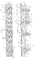
- On an upper end portion of each of the supporting frames 1 is fixedly mounted a hollow frame 2 to which a stationary grating table is fixed, which stationary grating table comprises a plurality of stationary rails 3a which are disposed in parallel with each other along the travelling path of a sand mold 16 and spaced apart from each other at predetermined intervals as shown in Figure 1.
- An upper surface of the stationary rail 3a is higher than the upper surface of the hollow frame 2.
- first movable rails 3b-1 and second movable rails 3b-2 Between the stationary rails 3a are disposed a plurality of first movable rails 3b-1 and second movable rails 3b-2, an upper surface of each of which movable rails 3b-1 and 3b-2 is lower than the upper surface of the stationary rails 3a.
- Each of the first movable rails 3b-1 is aligned in series with a respective second movable rail 3b-2 so as together to correspond in length to each of the stationary rails 3a, and the cross-sectional shape of each of the movable rails 3b-1 and 3b-2 is substantially identical with that of the stationary rail 3a.
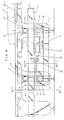
- a mounting base In a lower inside portion of each of the supporting frames 1 is provided a mounting base on which a pair of bearings 4 are fixedly mounted.
- a roller 5 is rotatably supported on the bearings 4.
- a travelling frame 6 is provided so as to extend along and beneath the travelling path of the sand mold 16.
- a short rail 7 is provided on a lower surface of the travelling frame 6 so as to correspond to the roller 5, such that the short rail 7 is brought into contact with the roller 5 as shown in Figure 5.
- On the upper surface of the travelling frame is located a lifting cylinder 8-1 disposed under the movable rails 3b-1.
- On an upper surface of the lifting cylinder 8-1 is fixedly mounted a base plate 9 on an upper surface of which leg bases 10 are mounted so as to support one each of the first movable rails 3b-1.
- leg bases 10 are installed in parallel with each other so as to correspond to the first movable rails 3b-1.
- another lifting cylinder 8-2 is located on the upper surface of the travelling frame 6 so as to be disposed under the movable rails 3b-2.
- On an upper surface of the lifting cylinder 8-2 is fixedly mounted a base plate 9 on an upper surface of which leg bases 10 are mounted so as to support one each of the second movable rails 3b-2. Consequently, these leg bases 10 are also installed in parallel with each other, as in the case of the first movable rails 3b-1, so as to correspond to the second movable rails 3b-2.
- a driving mechanism for the travelling frame 6 As shown in these drawings, a base 11 is provided under the travelling frame 6 so as to extend centrally along the travelling path of the sand mold 16 between longitudinally adjacent supporting frames 1. On an upper surface of the base 11 is mounted a driving cylinder 12 from which a piston rod 13 projects, in an advancing direction of a sand mold 16, a front end portion of which piston rod 13 being connected to a connecting segment 14 which projects from the travelling frame 6.
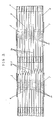
- the pouring station table 15 is positioned adjacent a molding station machine, which is positioned to the right of the hollow frame 2 as shown in Figure 2.
- Each sand mold 16, prepared in the molding station machine is received on to the upper surfaces of the stationary grating table 3a and, sequentially, first and second movable rails 3b-1 and 3b-2, such that each sand mold 16 is advanced along its travelling path on the pouring station table 15 each time a sand mold 16 is prepared and pushed out of the molding station machine.
- the sand molds prepared in the molding station machine are thus brought into close contact with each other in series along the pouring station table 15, i.e., on the upper surfaces of the stationary grating table 3a.
- the lifting cylinder 8-1 When a newly prepared sand mold 16 is pushed out of the molding station machine on to the pouring station table 15, the lifting cylinder 8-1 is actuated to lift the first movable rails 3b-1 to a position higher than the upper surface of the stationary grating table 3a so that about 4/5 of the total weight of the sand molds 16 positioned on the pouring station table 15 is supported by the thus lifted first movable rails 3b-1, the remaining 1/5 of the weight being supported by the stationary grating table 3a. Simultaneously, the driving cylinder 12 of the travelling frame 6 is fed with an actuating pressure just below that required to advance the travelling frame 6 along the travelling path of the sand molds 16.
- the lifting cylinder 8-1 is reversely actuated so as to lower the first movable rails 3b-1 to a position lower than the upper surface of the stationary grating table 3a, while the driving cylinder 12 is also reversely actuated so as to retract its piston rod 13, thus returning both the travelling frame 6 and the first movable rails 3b-1 to their initial positions, ready for a next advance operation of the sand molds 16 on the pouring station table 15.
- the second movable rails 3b-2 which are held stationary till that time, are lifted by the pushing cylinder 8-2 in synchronization with the lifting motion of the first movable rails 3b-1 by the lifting cylinder 8-1, to continue the sequential pushing operation of the sand molds 16. It is further possible to provide third, fourth, fifth movable rails and so on in addition to these first and second movable rails 3b-1 and 3b-2 in the pouring station table 15 of the present invention. Since the pouring station table 15 of the present invention enables a large number of the sand molds 16 to be transferred under the effect of a small pushing force acting thereon, the energy costs of conducting the pouring operation in the foundry are reduced.
Abstract
Description
- The present invention relates to pouring station tables in foundries in which a series of sand molds are sequentially pushed out of a molding machine, which sand molds are brought into contact with each other on the pouring station table, advanced therealong and subjected to a pouring operation, of molten metal, whilst thereon, according to the preamble of claim 1.
- In previous pouring station tables on which a series of sand molds are brought into contact with each other and transferred whilst in such contact, a stationary grating table is mounted on a supporting frame, along a travelling path of the sand molds subsequent to a molding machine to receive sand molds prepared in the molding machine. Each prepared sand mold is pushed out of the molding machine on to the stationary grating table and into contact with a preceding sand mold, so that the preceding sand mold is advanced along, or transferred from, the stationary grating table of the pouring station table whilst being subjected to the pouring operation. In order to advance a plurality of sand molds on such a stationary grating table, it is necessary to push the rearmost sand mold with a considerable pushing force. However, the sand mold may well not be able to withstand such a large pushing force. Consequently there is a problem in that sand molds are often broken by the pushing force required to advance the sand molds along the stationary grating table. U.S. 4,071,137, forming the preamble of claim 1, describes apparatus capable of overcoming the aforementioned difficulties, in which sand molds are conveyed on a so-called walking beam conveyor and the movable rails of the conveyor are moved vertically by fluid pressure bearings which also facilitate horizontal movement of the movable rails. Such an arrangement is unnecessarily complicated. It is an object of the present invention to provide a foundry pouring station table which is simple of construction and operation.
- According to the present invention there is provided a foundry pouring station table including a stationary grating table comprising a plurality of stationary rails which are fixedly mounted in spaced apart relationship on a hollow frame to extend parallel to each other along the travelling path of a sand mold, at least one movable rail shorter than said stationary rails and disposed between two adjacent stationary rails, a travelling frame located under said hollow frame so as to be translated in an advancing direction of said sand mold and carrying support means for said movable rail adjustable to locate the upper surface of the movable rail either below or slightly above the upper surface of said adjacent stationary rails, and a driving cylinder for said travelling frame located at a lower position in said hollow frame; characterised in that said travelling frame is supported on rollers for translation in said advancing direction of the said mold upon actuation of said driving cylinder and said support means is a lifting cylinder mounted on an upper surface of said travelling frame.
- In order that the invention may be well understood, one embodiment thereof, which is given by way of example only, will now be described, reference being made to the accompanying drawings, in which:
- Figure 1 is a plan view of a pouring station table of a preferred embodiment of the present invention;
- Figure 2 is a sectional view taken along the line II-II of Figure 1;
- Figure 3 is a partial plan view, enlarged relative to Figures 1 and 2, of a pouring station table;
- Figure 4 is an enlarged front view of a driving mechanism of a travelling frame of a pouring station table;
- Figure 5 is a sectional view taken along the line V-V of Figure 4; and
- Figure 6 is a sectional view taken along the line VI-VI of Figure 4.
- As shown in Figures 1, 2 and 3, a suitable number of vertical supporting frames or legs 1 are installed on a floor of the foundry at suitable intervals along a line extending from left to right in each of Figures 1, 2 and 3. On an upper end portion of each of the supporting frames 1 is fixedly mounted a
hollow frame 2 to which a stationary grating table is fixed, which stationary grating table comprises a plurality of stationary rails 3a which are disposed in parallel with each other along the travelling path of asand mold 16 and spaced apart from each other at predetermined intervals as shown in Figure 1. An upper surface of the stationary rail 3a is higher than the upper surface of thehollow frame 2. Between the stationary rails 3a are disposed a plurality of first movable rails 3b-1 and second movable rails 3b-2, an upper surface of each of which movable rails 3b-1 and 3b-2 is lower than the upper surface of the stationary rails 3a. Each of the first movable rails 3b-1 is aligned in series with a respective second movable rail 3b-2 so as together to correspond in length to each of the stationary rails 3a, and the cross-sectional shape of each of the movable rails 3b-1 and 3b-2 is substantially identical with that of the stationary rail 3a. In a lower inside portion of each of the supporting frames 1 is provided a mounting base on which a pair ofbearings 4 are fixedly mounted. Aroller 5 is rotatably supported on thebearings 4. Between the supporting frames 1 atravelling frame 6 is provided so as to extend along and beneath the travelling path of thesand mold 16. Ashort rail 7 is provided on a lower surface of thetravelling frame 6 so as to correspond to theroller 5, such that theshort rail 7 is brought into contact with theroller 5 as shown in Figure 5. On the upper surface of the travelling frame is located a lifting cylinder 8-1 disposed under the movable rails 3b-1. On an upper surface of the lifting cylinder 8-1 is fixedly mounted abase plate 9 on an upper surface of whichleg bases 10 are mounted so as to support one each of the first movable rails 3b-1. Consequently, as shown in Figure 5, theseleg bases 10 are installed in parallel with each other so as to correspond to the first movable rails 3b-1. Similarly, another lifting cylinder 8-2 is located on the upper surface of thetravelling frame 6 so as to be disposed under the movable rails 3b-2. On an upper surface of the lifting cylinder 8-2 is fixedly mounted abase plate 9 on an upper surface of whichleg bases 10 are mounted so as to support one each of the second movable rails 3b-2. Consequently, theseleg bases 10 are also installed in parallel with each other, as in the case of the first movable rails 3b-1, so as to correspond to the second movable rails 3b-2. - In Figures 4, 5 and 6, there is shown a driving mechanism for the
travelling frame 6. As shown in these drawings, a base 11 is provided under thetravelling frame 6 so as to extend centrally along the travelling path of thesand mold 16 between longitudinally adjacent supporting frames 1. On an upper surface of the base 11 is mounted a drivingcylinder 12 from which apiston rod 13 projects, in an advancing direction of asand mold 16, a front end portion of whichpiston rod 13 being connected to a connectingsegment 14 which projects from thetravelling frame 6. - The action of the pouring station table in operation will now be described with reference to the drawings.
- The pouring station table 15 is positioned adjacent a molding station machine, which is positioned to the right of the
hollow frame 2 as shown in Figure 2. Eachsand mold 16, prepared in the molding station machine, is received on to the upper surfaces of the stationary grating table 3a and, sequentially, first and second movable rails 3b-1 and 3b-2, such that eachsand mold 16 is advanced along its travelling path on the pouring station table 15 each time asand mold 16 is prepared and pushed out of the molding station machine. The sand molds prepared in the molding station machine are thus brought into close contact with each other in series along the pouring station table 15, i.e., on the upper surfaces of the stationary grating table 3a. When a newly preparedsand mold 16 is pushed out of the molding station machine on to the pouring station table 15, the lifting cylinder 8-1 is actuated to lift the first movable rails 3b-1 to a position higher than the upper surface of the stationary grating table 3a so that about 4/5 of the total weight of thesand molds 16 positioned on the pouring station table 15 is supported by the thus lifted first movable rails 3b-1, the remaining 1/5 of the weight being supported by the stationary grating table 3a. Simultaneously, the drivingcylinder 12 of thetravelling frame 6 is fed with an actuating pressure just below that required to advance thetravelling frame 6 along the travelling path of thesand molds 16. Under such circumstances, when a further newly preparedsand mold 16 is pushed out of the molding station machine on to the pouring station table 15, suchfurther sand mold 16 pushes therearmost sand mold 16 disposed on the pouring station table 15 forward. Such pushing force applied to therearmost sand mold 16 is in turn applied to the first movable rails 3b-1 through friction therebetween and to thetravelling frame 6 through theleg bases 10, thebase plates 9 and the lifting cylinders 8-1, while thetravelling frame 6 is under the influence of the drivingcylinder 12 which has been already energized as described above so that the first movable rails 3b-1 advance, together with thetravelling frame 6, by a distance corresponding to the width of asand mold 16, leftward in Figure 4, under the influence of theenergized driving cylinder 12 andpiston rod 13. Thus, the sliding friction between the stationary grating table 3a and thesand molds 16 thereon, whilst advancing thesand molds 16 along the pouring station table 15, is reduced. Also, since the rolling friction between theroller 5 and theshort rail 7 is small, it is possible to transfer thesand molds 16 by means of the movable rails with a small pushing force. Thus, sand mold failure is prevented and thinner or larger sand molds may be made, for providing larger mold cavities. - After completion of the advance of the
sand molds 16 on the pouring station table 15 by the width of asand mold 16, the lifting cylinder 8-1 is reversely actuated so as to lower the first movable rails 3b-1 to a position lower than the upper surface of the stationary grating table 3a, while the drivingcylinder 12 is also reversely actuated so as to retract itspiston rod 13, thus returning both thetravelling frame 6 and the first movable rails 3b-1 to their initial positions, ready for a next advance operation of thesand molds 16 on the pouring station table 15. - When the area of the pouring station table 15 corresponding to the first movable rails 3b-1 is fully covered by the sequentially advancing
sand molds 16, the second movable rails 3b-2, which are held stationary till that time, are lifted by the pushing cylinder 8-2 in synchronization with the lifting motion of the first movable rails 3b-1 by the lifting cylinder 8-1, to continue the sequential pushing operation of thesand molds 16. It is further possible to provide third, fourth, fifth movable rails and so on in addition to these first and second movable rails 3b-1 and 3b-2 in the pouring station table 15 of the present invention. Since the pouring station table 15 of the present invention enables a large number of thesand molds 16 to be transferred under the effect of a small pushing force acting thereon, the energy costs of conducting the pouring operation in the foundry are reduced.
Claims (3)
Applications Claiming Priority (1)
| Application Number | Priority Date | Filing Date | Title |
|---|---|---|---|
| PCT/JP1982/000150 WO1983003785A1 (en) | 1982-04-30 | 1982-04-30 | Molten metal filling table in molding machine |
Publications (3)
| Publication Number | Publication Date |
|---|---|
| EP0108148A1 EP0108148A1 (en) | 1984-05-16 |
| EP0108148A4 EP0108148A4 (en) | 1984-09-06 |
| EP0108148B1 true EP0108148B1 (en) | 1988-01-13 |
Family
ID=13762241
Family Applications (1)
| Application Number | Title | Priority Date | Filing Date |
|---|---|---|---|
| EP82901309A Expired EP0108148B1 (en) | 1982-04-30 | 1982-04-30 | A foundry pouring station table |
Country Status (3)
| Country | Link |
|---|---|
| EP (1) | EP0108148B1 (en) |
| DE (1) | DE3277965D1 (en) |
| WO (1) | WO1983003785A1 (en) |
Families Citing this family (4)
| Publication number | Priority date | Publication date | Assignee | Title |
|---|---|---|---|---|
| NL8800728A (en) * | 1988-03-23 | 1989-10-16 | Jetske Rutte Geb Hoekstra | TRANSPARENT FLOOR, EQUIVALENT BEAMS, IN PARTICULAR FOR A WASTE COMPOSING PLANT. |
| JP4447482B2 (en) * | 2005-02-14 | 2010-04-07 | 株式会社ノリタケカンパニーリミテド | Walking beam heat treatment equipment |
| US7980282B2 (en) | 2007-10-02 | 2011-07-19 | Caterpillar Inc. | Tire system for an off-highway machine |
| US7640996B2 (en) | 2007-10-02 | 2010-01-05 | Caterpillar Inc. | Walking beam and tire system for an earthmoving scraping device |
Citations (1)
| Publication number | Priority date | Publication date | Assignee | Title |
|---|---|---|---|---|
| JPS5375116A (en) * | 1976-12-13 | 1978-07-04 | Auburn Foundry | Conveyor device and its operating method |
Family Cites Families (2)
| Publication number | Priority date | Publication date | Assignee | Title |
|---|---|---|---|---|
| FR1346487A (en) * | 1962-11-09 | 1963-12-20 | Baele Gangloff Ste Nouvelle | Device for transporting various objects, in particular containers |
| JPS51106963A (en) * | 1975-03-14 | 1976-09-22 | Nippon Steel Corp | JOZAINOHAIRETSUSOCHI |
-
1982
- 1982-04-30 WO PCT/JP1982/000150 patent/WO1983003785A1/en active IP Right Grant
- 1982-04-30 EP EP82901309A patent/EP0108148B1/en not_active Expired
- 1982-04-30 DE DE8282901309T patent/DE3277965D1/en not_active Expired
Patent Citations (1)
| Publication number | Priority date | Publication date | Assignee | Title |
|---|---|---|---|---|
| JPS5375116A (en) * | 1976-12-13 | 1978-07-04 | Auburn Foundry | Conveyor device and its operating method |
Also Published As
| Publication number | Publication date |
|---|---|
| EP0108148A4 (en) | 1984-09-06 |
| WO1983003785A1 (en) | 1983-11-10 |
| EP0108148A1 (en) | 1984-05-16 |
| DE3277965D1 (en) | 1988-02-18 |
Similar Documents
| Publication | Publication Date | Title |
|---|---|---|
| CA2161773C (en) | Method and apparatus for changing dies in thermoforming presses | |
| GB1233441A (en) | ||
| US4270655A (en) | Walking-beam conveyer | |
| US3824062A (en) | Track-type molding apparatus and carriage means therefor | |
| EP0108148B1 (en) | A foundry pouring station table | |
| IL42129A (en) | Apparatus for the production of cast concrete members | |
| EP0035568B1 (en) | Brick forming apparatus | |
| US3989094A (en) | Apparatus for producing castings from flaskless sand molds | |
| JPH0852561A (en) | Device and method for carrying casting mold | |
| JP4567174B2 (en) | Mold changer for press machine | |
| JP3297442B2 (en) | Pile changer | |
| US4364471A (en) | Automatic accumulating lift and carry transfer mechanism | |
| US3659701A (en) | Cooling conveyor | |
| EP0916461B1 (en) | Pressing device | |
| JP3724900B2 (en) | Cylinder sleeve transfer device | |
| US3969061A (en) | Concrete press with mold clamping means | |
| US3646643A (en) | Apparatus for cutting semiplastic bodies of cellular lightweight concrete | |
| JPH07115240B2 (en) | Loader / Unloader for multi-stage press machine | |
| CS195671B2 (en) | Facility for the continuous arranging of the moulds | |
| RU2056025C1 (en) | Device for loading and unloading blanks out of a furnace | |
| CN215207067U (en) | Automatic feeding device for long section and long material | |
| CN112453339B (en) | Steel splitting system for continuous casting | |
| US3318365A (en) | Apparatus for producing half molds by pressing | |
| JP2500481B2 (en) | Pallet feeder for concrete block molding machine | |
| JPS5945463B2 (en) | Transfer device for surface plate device |
Legal Events
| Date | Code | Title | Description |
|---|---|---|---|
| PUAI | Public reference made under article 153(3) epc to a published international application that has entered the european phase |
Free format text: ORIGINAL CODE: 0009012 |
|
| 17P | Request for examination filed |
Effective date: 19831229 |
|
| AK | Designated contracting states |
Kind code of ref document: A1 Designated state(s): DE GB |
|
| GRAA | (expected) grant |
Free format text: ORIGINAL CODE: 0009210 |
|
| AK | Designated contracting states |
Kind code of ref document: B1 Designated state(s): DE GB |
|
| REF | Corresponds to: |
Ref document number: 3277965 Country of ref document: DE Date of ref document: 19880218 |
|
| PLBE | No opposition filed within time limit |
Free format text: ORIGINAL CODE: 0009261 |
|
| STAA | Information on the status of an ep patent application or granted ep patent |
Free format text: STATUS: NO OPPOSITION FILED WITHIN TIME LIMIT |
|
| 26N | No opposition filed | ||
| PGFP | Annual fee paid to national office [announced via postgrant information from national office to epo] |
Ref country code: DE Payment date: 19890921 Year of fee payment: 8 |
|
| PGFP | Annual fee paid to national office [announced via postgrant information from national office to epo] |
Ref country code: GB Payment date: 19890930 Year of fee payment: 8 |
|
| PG25 | Lapsed in a contracting state [announced via postgrant information from national office to epo] |
Ref country code: GB Effective date: 19900430 |
|
| PG25 | Lapsed in a contracting state [announced via postgrant information from national office to epo] |
Ref country code: DE Effective date: 19910101 |
|
| GBPC | Gb: european patent ceased through non-payment of renewal fee |