EP0107966A2 - Load cell and method for its manufacture - Google Patents
Load cell and method for its manufacture Download PDFInfo
- Publication number
- EP0107966A2 EP0107966A2 EP83306472A EP83306472A EP0107966A2 EP 0107966 A2 EP0107966 A2 EP 0107966A2 EP 83306472 A EP83306472 A EP 83306472A EP 83306472 A EP83306472 A EP 83306472A EP 0107966 A2 EP0107966 A2 EP 0107966A2
- Authority
- EP
- European Patent Office
- Prior art keywords
- load
- strain gauge
- sensitive element
- load cell
- deposited
- Prior art date
- Legal status (The legal status is an assumption and is not a legal conclusion. Google has not performed a legal analysis and makes no representation as to the accuracy of the status listed.)
- Granted
Links
- 238000000034 method Methods 0.000 title claims description 12
- 238000004519 manufacturing process Methods 0.000 title claims description 8
- 229910052782 aluminium Inorganic materials 0.000 claims abstract description 90
- XAGFODPZIPBFFR-UHFFFAOYSA-N aluminium Chemical compound [Al] XAGFODPZIPBFFR-UHFFFAOYSA-N 0.000 claims abstract description 88
- 239000000758 substrate Substances 0.000 claims abstract description 28
- 239000004411 aluminium Substances 0.000 claims abstract description 22
- 239000000853 adhesive Substances 0.000 claims abstract description 19
- 230000001070 adhesive effect Effects 0.000 claims abstract description 19
- 229920001971 elastomer Polymers 0.000 claims description 21
- 239000004809 Teflon Substances 0.000 claims description 17
- 229920006362 Teflon® Polymers 0.000 claims description 17
- 239000005030 aluminium foil Substances 0.000 claims description 3
- 230000008021 deposition Effects 0.000 claims description 2
- 230000035515 penetration Effects 0.000 claims description 2
- 230000002093 peripheral effect Effects 0.000 claims 1
- 238000007789 sealing Methods 0.000 claims 1
- 239000010408 film Substances 0.000 description 27
- 239000011888 foil Substances 0.000 description 19
- 229920002379 silicone rubber Polymers 0.000 description 11
- 239000004945 silicone rubber Substances 0.000 description 11
- 238000005303 weighing Methods 0.000 description 10
- 230000002411 adverse Effects 0.000 description 7
- 230000000694 effects Effects 0.000 description 5
- 230000015572 biosynthetic process Effects 0.000 description 4
- 230000006835 compression Effects 0.000 description 4
- 238000007906 compression Methods 0.000 description 4
- 229920000728 polyester Polymers 0.000 description 4
- 239000000565 sealant Substances 0.000 description 4
- 238000007740 vapor deposition Methods 0.000 description 4
- 238000007598 dipping method Methods 0.000 description 3
- 238000006073 displacement reaction Methods 0.000 description 3
- 239000000463 material Substances 0.000 description 3
- 229920003223 poly(pyromellitimide-1,4-diphenyl ether) Polymers 0.000 description 3
- NIXOWILDQLNWCW-UHFFFAOYSA-N acrylic acid group Chemical group C(C=C)(=O)O NIXOWILDQLNWCW-UHFFFAOYSA-N 0.000 description 2
- 239000002390 adhesive tape Substances 0.000 description 2
- 239000011248 coating agent Substances 0.000 description 2
- 238000000576 coating method Methods 0.000 description 2
- 229910052751 metal Inorganic materials 0.000 description 2
- 239000002184 metal Substances 0.000 description 2
- 229920002635 polyurethane Polymers 0.000 description 2
- 239000004814 polyurethane Substances 0.000 description 2
- 239000003522 acrylic cement Substances 0.000 description 1
- 125000000484 butyl group Chemical group [H]C([*])([H])C([H])([H])C([H])([H])C([H])([H])[H] 0.000 description 1
- 229920005549 butyl rubber Polymers 0.000 description 1
- 230000007423 decrease Effects 0.000 description 1
- 230000002939 deleterious effect Effects 0.000 description 1
- 238000000151 deposition Methods 0.000 description 1
- 230000006866 deterioration Effects 0.000 description 1
- 230000001747 exhibiting effect Effects 0.000 description 1
- 238000010422 painting Methods 0.000 description 1
- 230000000149 penetrating effect Effects 0.000 description 1
- 229920001296 polysiloxane Polymers 0.000 description 1
- -1 polytetrafluoroethylene Polymers 0.000 description 1
- 229920001343 polytetrafluoroethylene Polymers 0.000 description 1
- 239000004810 polytetrafluoroethylene Substances 0.000 description 1
- 239000011527 polyurethane coating Substances 0.000 description 1
- 230000000452 restraining effect Effects 0.000 description 1
- 239000003566 sealing material Substances 0.000 description 1
- 239000010409 thin film Substances 0.000 description 1
- XLYOFNOQVPJJNP-UHFFFAOYSA-N water Substances O XLYOFNOQVPJJNP-UHFFFAOYSA-N 0.000 description 1
Images


Classifications
-
- G—PHYSICS
- G01—MEASURING; TESTING
- G01L—MEASURING FORCE, STRESS, TORQUE, WORK, MECHANICAL POWER, MECHANICAL EFFICIENCY, OR FLUID PRESSURE
- G01L1/00—Measuring force or stress, in general
- G01L1/20—Measuring force or stress, in general by measuring variations in ohmic resistance of solid materials or of electrically-conductive fluids; by making use of electrokinetic cells, i.e. liquid-containing cells wherein an electrical potential is produced or varied upon the application of stress
- G01L1/22—Measuring force or stress, in general by measuring variations in ohmic resistance of solid materials or of electrically-conductive fluids; by making use of electrokinetic cells, i.e. liquid-containing cells wherein an electrical potential is produced or varied upon the application of stress using resistance strain gauges
- G01L1/2206—Special supports with preselected places to mount the resistance strain gauges; Mounting of supports
- G01L1/2243—Special supports with preselected places to mount the resistance strain gauges; Mounting of supports the supports being parallelogram-shaped
-
- G—PHYSICS
- G01—MEASURING; TESTING
- G01G—WEIGHING
- G01G3/00—Weighing apparatus characterised by the use of elastically-deformable members, e.g. spring balances
- G01G3/12—Weighing apparatus characterised by the use of elastically-deformable members, e.g. spring balances wherein the weighing element is in the form of a solid body stressed by pressure or tension during weighing
- G01G3/14—Weighing apparatus characterised by the use of elastically-deformable members, e.g. spring balances wherein the weighing element is in the form of a solid body stressed by pressure or tension during weighing measuring variations of electrical resistance
- G01G3/1402—Special supports with preselected places to mount the resistance strain gauges; Mounting of supports
- G01G3/1412—Special supports with preselected places to mount the resistance strain gauges; Mounting of supports the supports being parallelogram shaped
-
- G—PHYSICS
- G01—MEASURING; TESTING
- G01L—MEASURING FORCE, STRESS, TORQUE, WORK, MECHANICAL POWER, MECHANICAL EFFICIENCY, OR FLUID PRESSURE
- G01L1/00—Measuring force or stress, in general
- G01L1/20—Measuring force or stress, in general by measuring variations in ohmic resistance of solid materials or of electrically-conductive fluids; by making use of electrokinetic cells, i.e. liquid-containing cells wherein an electrical potential is produced or varied upon the application of stress
- G01L1/22—Measuring force or stress, in general by measuring variations in ohmic resistance of solid materials or of electrically-conductive fluids; by making use of electrokinetic cells, i.e. liquid-containing cells wherein an electrical potential is produced or varied upon the application of stress using resistance strain gauges
- G01L1/2287—Measuring force or stress, in general by measuring variations in ohmic resistance of solid materials or of electrically-conductive fluids; by making use of electrokinetic cells, i.e. liquid-containing cells wherein an electrical potential is produced or varied upon the application of stress using resistance strain gauges constructional details of the strain gauges
Definitions
- This invention relates to a load cell used primarily with scales, and seeks to enhance load cell durability.
- a load cell of the aforementioned type comprises a load-sensitive element which develops strain the magnitude of which corresponds to an applied load, and a strain gauge cemented to the load-sensitive element to detect the amount of strain electrically. It is necessary to protect the strain gauge against moisture and humidity in order to enhance its durability and maintain good operating performance. Conventional practice has been to either coat the strain gauge with a moistureproof material such as silicone rubber, or seal the strain gauge by means of a metal foil. However, the former technique does not provide sufficient protection against moisture in the moist and humid environments where load cells commonly find use in scales.
- the metal foil has little stretchability and'therefore hinders the deformation of the load-sensitive element, thereby having an adverse effect upon the load-sensitive element, thereby having an adverse effect upon the load-strain characteristic of the load-sensitive element.
- a load cell comprises a load-sensitive element having at least one portion reduced in thickness for providing flexibility; and a strain gauge affixed to the or each reduced-thickness portion, the strain gauge being protected by one or more layers of aluminium or Teflon.
- the present invention improves the durability of a load cell by effectively protecting the strain gauge against water and moisture without adversely affecting the load-strain characteristic of the load-sensitive element. It also improves the durability of the load cell without inviting any decline in the accuracy thereof by subjecting the strain gauge to a moistureproofing treatment without hampering the function of the strain gauge.
- each strain gauge is an extremely thin film having a thickness of from ten to at most several thousand angstroms, each is covered with a uniform, non-porous aluminium deposited layer exhibiting exeellent flexibility and elasticity or with, preferably non-adhesively, a Teflon sheet ("Teflon" is the trademark for polytetrafluoroethylene).
- Teflon is the trademark for polytetrafluoroethylene.
- the Teflon sheet may in turn be covered with a suitable covering member.
- the load-sensitive element has a quadrilateral configuration and comprises a rigid, fixed portion at one extremity of the quadrilateral, a rigid, movable portion at the other extremity of the quadrilateral, and upper and lower beams interconnecting the upper and lower ends, respectively, of the rigid portions, the fixed portions and the upper and lower beams defining a hollow portion within the quadrilateral, and the upper and lower beams each having a portion reduced in thickness for providing flexibility; a strain gauge is affixed to each reduced-thickness portion with a rubber sheet having an aperture provided on the load-sensitive element in such a manner that the strain gauge is situated within the aperture, and a-deposited aluminium film or aluminium foil is provided on the load-sensitive element and the rubber sheet so as to seal the strain gauge in the aperture.
- a method of manufacturing a load cell includes affixing a strain gauge to a reduced-thickness portion of a load-sensitive element;and covering the strain g 'auge with a deposited aluminium film comprising a substrate and a deposited aluminium layer provided on a surface of the substrate.
- deposited aluminum film a film obtained by providing one surface of a film substrate with a layer of deposited aluminum
- deposited aluminum tape a film obtained by coating this deposited aluminum film beforehand with an adhesive
- numeral 1 denotes a load cell mounted by brackets C, D betweeen a scale body A and a weighing platform B provided thereon.
- a load-sensitive element 2 constitutes the main body of the load cell 1 and is the element which develops strain when subjected to an applied load. As shown in Fig. 1, numeral 1 denotes a load cell mounted by brackets C, D betweeen a scale body A and a weighing platform B provided thereon.
- a load-sensitive element 2 constitutes the main body of the load cell 1 and is the element which develops strain when subjected to an applied load. As shown in Fig.
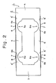
- the load-sensitive element 2 has a hollow, quadrilateral configuration and comprises a rigid, fixed portion 3 at one extremity of the quadrilateral which is fixedly secured to the scale body A by the bracket C, a rigid, movable portion 4 at the other extremity of the quadrilateral to which the weighing platform B is affixed by the bracket D, and upper and lower beams 5, 6 interconnecting the upper and lower ends, respectively, of the rigid portions 3, 4.
- the upper beam 5 is provided at two locations with flexible portions 5b formed by reducing the thickness of the beam by the formation of semicircular cut-outs 5a on the inner side thereof.
- the lower beam 6 is provided at two locations with flexible portions 6b formed by reducing the thickness of the beam by the formation of semicircular cut-outs 6a on the inner side thereof.
- a strain gauge 7 is bonded to the outer surface of each flexible portion.
- the upper and lower beams 5, 6 have respective bonding surfaces 5', 6' to which the strain gauges 7 are bonded.
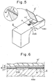
- a deposited aluminum film 8 is bonded to each of these surfaces 5', 6' so as to cover the respective strain gauge 7.
- the film 8 comprises a film substrate 9 made of polyester or the like, and a non-porous deposited aluminum layer 10 formed on one suface of the film substrate 9 by a vapor deposition technique. This deposited aluminum film 8 is bonded to each of the bonding surfaces 5', 6' of the upper and lower beams 5, 6 through use of a polyurethane or like adhesive 11.
- the entirety of the load-sensitive element 2 may be coated with a silicone rubber layer 12, as shown in Fig. 4. This is accomplished by first subjecting the element to a primer treatment to improve the adherence of the silicone rubber layer thereto, and then dipping the element into a silicone rubber solution.
- the movable portion 4 of the load-sensitive element 2 constituting the load cell 1 is displaced downwardly owing to the applied load.
- the surfaces at which the strain gauges 7 are bonded to the flexible portions 5b, 6b of the upper and lower beams 5, 6 experience either tension or compression, which is in turn transmitted to the respective strain gauges.
- the result is a change in the electrical-resistance of each strain gauge.
- the amount of strain developed by the load-sensitive element 2, which strain corresponds to the weight of the article on the weighing platform may be detected through electrical means.
- the deposited aluminum film 8 is bonded over the strain gauges 7, so that each strain gauge is covered by the non-porous deposited aluminum layer 10 constituting the film. Owing to the waterproof and moistureproof properties of the deposited aluminum layer 10, protection of the strain gauges against moisture and humidity is assured even if the scale is employed in an extremely wet or humid environment. Since the substrate 9 and deposited aluminum layer 10 constituting the film 8 exhibit sufficient flexibility and elasticity, the film 8 will not impede the deformation of the load-sensitive element 2 when a load is applied thereto.
- the deposited aluminum film 8 of the first embodiment is replaced by a deposited aluminum tape 8'.
- the tape 8' comprises a substrate 9 1 made of polyester or the like, and a deposited aluminum layer 10' provided on one surface of the substrate 9'. Further, an acrylic or like adhesive 11' is applied in advance to the exposed surface of the deposited aluminum layer 10', namely to the side thereof opposite the substrate 9'.
- the deposited aluminum tape 8' is bonded directly, by virtue of the adhesive 11', to the strain gauge bonding . surfaces 5', 6' on the beams 5, 6 of the load-sensitive element 2.
- a Kapton adhesive tape 13' ( "Kapton” is a trademark, it is manufactured by duPont) is applied to the electrically exposed connections 7a of the strain gauge 7 for the purpose of insulating the connections from the deposited aluminum layer 10', which is electrically conductive.
- a third embodiment of the invention is illustrated in Figs. 7 and 8.
- the strain gauge bonding surface 5' is subjected to an aluminum vapor deposition treatment to coat the strain gauge 7 with a deposited aluminum layer 10".
- the layers consisting of the film substrate 9 and adhesive 11 or 11' of the first and second embodiments are not interposed between the bonding surface 5' of the load-sensitive element 2 and the deposited aluminum layer 10".
- the strain gauge 7 is directly coated with the deposited aluminum layer 10" to improve the adherence between the layer 10" and both the strain gauge and strain gauge bonding surface. This provides the strain gauge 7 with even greater protection against moisture and humidity.
- a strip of Kapton adhesive tape 13" is applied to these connections. It is also necessary to prevent aluminum molecules from penetrating a paper covering the grid 7b of the strain gauge 7. To this end, a polyurethane coating 14" is applied to the grid 7b before carrying out the aluminum deposition treatment.
- Fig. 9 illustrates a fourth embodiment of the present invention.
- a discontinuous or step-like portion susceptible to the penetration of humidity may be formed where the deposited aluminum layer 10 (10') meets the surface of the load-sensitive element 2 along the edge of the deposited aluminum film 8 or deposited aluminum tape 8'.
- This embodiment seeks to improve upon the foregoing arrangement by forming a deposited aluminum layer 15''' extending from the edge portion 8a''' of the deposited aluminum film (or deposited aluminum tape) 8'''' to the surface of the load-sensitive element 2.
- the layer 15''' is formed by an aluminum vapor deposition treatment.
- the deposited aluminum layer 15''' closes off the portion of discontinuity between the aluminum deposited layer 10''' and the surface of the load-sensitive element 2.
- a strain gauge bonded to the flexible portion of a load-sensitive element constituting a load cell is covered with a deposited aluminum layer.
- the strain gauge is therefore protected against moisture and humidity without any deleterious effect upon the load-strain characteristic of the load-sensitive element.
- the latter obtains from the fact that covering body offers little restraint to the deformation of the load-sensitive element.
- the result is a load cell having excellent performance and durability and, hence, a load cell suited for use in scales employed in extremely moist or humid environments.
- the strain gauge 7 is covered with a Teflon sheet 16, which is in turn coated completely, by a process such as painting or dipping, with a covering member 17 such as silicone rubber, butyl or polyurethane.
- a covering member 17 such as silicone rubber, butyl or polyurethane.
- the strain gauge 7 bonded to the surface of the load-sensitive element 2 at the flexible portion 5b (6b) is protected against moisture and humidity by the covering member 17.
- the Teflon sheet 16 is interposed between the strain gauge 7 and the covering member 17, without being adhered to the strain gauge, so that the strain gauge 7 is bonded solely to the load-sensitive element 2.
- the movable portion 4 of the load-sensitive element 2 is displaced downwardly owing to the applied load.
- the surfaces at which the strain gauges 7 are bonded to the flexible portions 5b, 6b of the upper and lower beams 5, 6 experience either tension or compression.
- the strain gauges 7 bonded to these surfaces are in no way constrained or restricted by the covering member 17, so that the strain gauges are free to stretch and relax and, hence, follow up the tension and compression of the flexible portions 5b, 6b in a faithful manner.
- the amount of strain developed by the load-sensitive element 2, namely the weight of the article on the weighing platform B, may be detected with great accuracy in the form of an electrical output from the strain gauges.
- a deposited aluminum tape 17 1 is used in place of the coating of silicone rubber or the like used as the covering member in the fifth embodiment described above.
- the deposited aluminum tape 17' comprises a substrate 17a' made of polyester or the like, and a deposited aluminum layer 17b' provided on one surface of the substrate 17a'. Further, an acrylic or like adhesive 17c' is applied in advance to the opposite side of the substrate 17a'.
- the foregoing deposited aluminum tape 17' is applied thereto and bonded to the surface of the load-sensitive element.
- the deposited aluminum tape 17' may be substituted by a deposited aluminum tape comprising the substrate 17a', the deposited aluminum layer 17b' provided on one surface of the substrate 17a, and the adhesive 17c' applied in advance to the exposed surface of the deposited aluminum layer 17b', rather than to the surface of the substrate 17a' opposite the deposited aluminum layer 17b'.
- a deposited aluminum film 17" is employed as the covering member.
- the deposited aluminum film 17" comprises a substrate 17a", and a deposited aluminum layer 17b" provided on one surface of the substrate 17a".
- the strain gauge 7 is covered non-adhesively with the Teflon sheet 16, the upper surface and periphery whereof are coated with an adhesive 18.
- the deposited aluminum film 17" is bonded to the adhesive 18.
- the covering member As in the seventh embodiment of Fig. 13, the strain gauge 7 is covered with the Teflon sheet 16, and the aluminum foil 17''' is bonded to the load-sensitive element 2 by the adhesive 18 so as to cover the Teflon sheet 16.
- the deposited aluminum layers 17b', 17b", or the aluminum foil 17"' protect the strain gauge 7 against moisture and humidity.
- the Teflon sheet 8 is interposed between the strain gauge 7 and the covering member 17',17",17''', allowing the strain gauge to follow up the deformation of the load-sensitive element 2 in a highly precise manner.
- a strain gauge bonded to the flexible portion of a load-sensitive element constituting a load cell is covered with a covering member through the intermediary of a Teflon sheet placed on the strain gauge but not adhered thereto.
- the strain gauge is therefore protected against moisture and humidity, and the covering material will not restrict or constrain the stretching and relaxation of the strain gauge as it follows up the deformation of the load-sensitive element.
- This provides a load cell which exhibits excellent performance and weighing accuracy, and which is suited for use in scales employed in extremely moist or humid environments.
- the load-sensitive element 2 has a hollow, quadrilateral configuration and comprises a rigid, -fixed portion 3 at one extremity of the quadrilateral which is fixedly secured to the scale body A by the bracket C, a rigid, movable portion 4 at the other extremity of the quadrilateral to which the weighing platform B is affixed by the bracket D, and upper and lower beams 5, 6 interconnecting the upper and lower ends, respectively, of the rigid portions 3, 4.
- the upper beam 5 is provided at two locations with flexible portions 5b formed by reducing the thickness of the beam by the formation of semicircular cut-outs 5a.
- the lower beam 6 is provided at two locations with flexible portions 6b formed by reducing the thickness of the beam by the formation of semicircular cut-outs 6a.
- a strain gauge 7 is bonded to the load-sensitive element 2 at each flexible portion thereof.
- the cut-outs 5a, 6a are formed on the outer side.of the upper and lower beams 5, 6, respectively. Accordingly, the strain gauges 7 are bonded to the inner sides of the upper and lower beams 5, 6, namely the sides facing the hollow portion 2a of the load-sensitive element 2, rather than to the outer sides thereof as in the embodiments described above.
- Numeral 19 denotes a covering body which, as shown in Fig.
- the covering body 19 comprises a rubber sheet 21 bonded to the side surface 2b of the load-sensitive element 2 through a sealant 20, and aluminum foil 22 bonded in place by the adhesive 11 so as to cover the rubber sheet 10 from the outside.
- the strain gauges 7 are covered while a space (the hollow portion 2a of the load-sensitive body 2) is provided around them.
- a silicone sealing material is suitable for use as the sealant 20, and an acrylic adhesive is suitable for use as the adhesive 11.
- a suitable material for use as the rubber sheet 21 is butyl rubber in view of the flexibility thereof.
- the entirety of the load-sensitive element 2 may be coated with a silicone rubber layer 23, as shown in Fig. 17. This is accomplished by first subjecting the element to a primer treatment, and then dipping the element into a silicone rubber solution.
- the movable portion 4 of the load-sensitive element 2 constituting the load cell 1 is displaced downwardly owing to the applied load.
- the surfaces at which the strain gauges 7 are bonded to the flexible portions 5b, 6b of the upper and lower beams 5, 6 experience either tension or compression, which is in turn transmitted to the respective strain gauges.
- the result is a change in the electrical resistance of each strain gauge.
- the amount of strain developed by the load-sensitive element 2, which strain corresponds to the weight of the article on the weighing platform may be detected through electrical means.
- the strain gauges 7 of the load cell 1 are covered with the covering body 19, which comprises the rubber sheet 21 bonded to the side surface 2b of the load-sensitive element 2, and the aluminum foil 22. Owing to the waterproof and moistureproof properties of ⁇ the aluminum foil 22, protection of the strain gauges against moisture and humidity is assured even if the scale is employed in an extremely wet or humid environment. Though the aluminum foil 22 lacks stretchability, deformation of the load-sensitive element 2 is in no way hampered because of the highly flexible rubber sheet 21 interposed between the foil 22 and the load-sensitive body 2. Further, since the strain gauges 7 are covered by means of the covering bodies 19 while the space 2a is provided around them, the covering bodies do not adversely affect the creep characteristic.
- the strain gauges 7 may'stretch and relax in excellent conformance with the stetching and relaxation of the strain gauge bonding surfaces located at the flexible portions 5b, 6b of the load-sensitive element 2.
- the strain gauges 7 can be protected against moisture and humidity without any deterioration in the load-strain characteristic of the load-sensitive element 2 or in the creep characteristic of the strain gauges being caused by a restraining forced imposed by the covering bodies 19.
- each strain gauge 7 is covered with a covering body 24.
- each covering body 24 comprises a rubber sheet 26 bonded to the surface of the load-sensitive element 2 by a sealant 25, and aluminum foil 28 bonded in place by an adhesive 27 so as to cover the rubber sheet from the outside.
- the rubber sheet 26 has an opening 26a and is bonded to the load-sensitive element 2 in such a manner that the strain gauge 7 will be situated in said opening.
- each strain gauge 7 is covered with the aluminum foil 28 bonded in place through the intermediary of the rubber sheet 26, which is interposed between the load-sensitive body 2 and the aluminum foil, a space.(the hollow portion 10a') being provided around the strain gauges.
- the strain gauges are protected against moisture and humidity without any adverse effect upon the load-strain characteristic of the load-sensitive body or the creep characteristic of the strain gauges.
- the entirety of the load-sensitive element 2 may be coated with a silicone rubber layer 29, as shown in Fig. 20.
- FIG. 21 This embodiment relates to a load cell 1 having strain gauges 7 bonded to the inner sides of upper and lower beams 5, 6 of a load-sensitive element 2, namely the sides of the beams facing the hollow portion 2a of the load-sensitive body 2.
- each strain gauge 7 is covered . with a covering body 24 which comprises a rubber sheet 26 bonded to the inner surface of the load-sensitive element 2 by a sealant, and aluminum foil 28 bonded in place by an adhesive so as to cover the rubber sheet from the outside.
- the rubber sheet 26 has an opening 26a and is bonded to the load-sensitive element 2 in such a manner that the strain gauge 7 will be situated in said opening.
- each strain gauge 7 is covered with the-aluminum foil 28 bonded in place through the intermediary of the rubber sheet 26, which is interposed between the load-sensitive body 2 and the aluminum foil, a space (the hollow portion 26a) being provided around the strain gauges.
- the strain gauges are protected against moisture and humidity without any adverse effect upon the load-strain characteristic of the load-sensitive body or the creep characteristic of the strain gauges.
- the entirety of the load-sensitive element 2 may be coated with a silicone rubber layer.
- the aluminum foils 22, 28 in the foregoing embodiments may be substituted by a deposited aluminum film comprising a substrate consisting primarily of polyester or the like, and a thin layer of aluminum formed on the surface of the substrate by vapor deposition.
- a strain gauge is bonded to the flexible portions of the upper and lower beams of a load-sensitive element constituting a load cell, and each strain gauge is covered with aluminum foil or a deposited aluminum film bonded in place through the intermediary of a rubber sheet interposed between the load-sensitive element and the foil or film, a space being provided around the strain gauges.
- the strain gauges are thus effectively protected against moisture and humidity without any adverse effect upon the load-strain characteristic of the load-sensitive element or the creep characteristic of the strain gauges.
- the result is a load cell having excellent performance and durability and, hence, a load cell suited for use in scales employed in extremely moist or humid environments.
Landscapes
- Physics & Mathematics (AREA)
- General Physics & Mathematics (AREA)
- Measurement Of Force In General (AREA)
Abstract
Description
- This invention relates to a load cell used primarily with scales, and seeks to enhance load cell durability.
- A load cell of the aforementioned type comprises a load-sensitive element which develops strain the magnitude of which corresponds to an applied load, and a strain gauge cemented to the load-sensitive element to detect the amount of strain electrically. It is necessary to protect the strain gauge against moisture and humidity in order to enhance its durability and maintain good operating performance. Conventional practice has been to either coat the strain gauge with a moistureproof material such as silicone rubber, or seal the strain gauge by means of a metal foil. However, the former technique does not provide sufficient protection against moisture in the moist and humid environments where load cells commonly find use in scales. While the latter expedient affords excellent protection against moisture, the metal foil has little stretchability and'therefore hinders the deformation of the load-sensitive element, thereby having an adverse effect upon the load-sensitive element, thereby having an adverse effect upon the load-strain characteristic of the load-sensitive element.
- In accordance with one aspect of the present invention a load cell comprises a load-sensitive element having at least one portion reduced in thickness for providing flexibility; and a strain gauge affixed to the or each reduced-thickness portion, the strain gauge being protected by one or more layers of aluminium or Teflon.
- The present invention improves the durability of a load cell by effectively protecting the strain gauge against water and moisture without adversely affecting the load-strain characteristic of the load-sensitive element. It also improves the durability of the load cell without inviting any decline in the accuracy thereof by subjecting the strain gauge to a moistureproofing treatment without hampering the function of the strain gauge.
- Since each strain gauge is an extremely thin film having a thickness of from ten to at most several thousand angstroms, each is covered with a uniform, non-porous aluminium deposited layer exhibiting exeellent flexibility and elasticity or with, preferably non-adhesively, a Teflon sheet ("Teflon" is the trademark for polytetrafluoroethylene). In the preferable case since Teflon is difficult to bond chemically, the Teflon sheet may in turn be covered with a suitable covering member.
- In one example, the load-sensitive element has a quadrilateral configuration and comprises a rigid, fixed portion at one extremity of the quadrilateral, a rigid, movable portion at the other extremity of the quadrilateral, and upper and lower beams interconnecting the upper and lower ends, respectively, of the rigid portions, the fixed portions and the upper and lower beams defining a hollow portion within the quadrilateral, and the upper and lower beams each having a portion reduced in thickness for providing flexibility; a strain gauge is affixed to each reduced-thickness portion with a rubber sheet having an aperture provided on the load-sensitive element in such a manner that the strain gauge is situated within the aperture, and a-deposited aluminium film or aluminium foil is provided on the load-sensitive element and the rubber sheet so as to seal the strain gauge in the aperture.
- In this example, due to the stretching action of the rubber sheet bonded directly over the strain gauge and providing a space around the strain gauge, the creep characteristic of the load cell is unaffected.
- In accordance with a second aspect of the present invention, a method of manufacturing a load cell includes affixing a strain gauge to a reduced-thickness portion of a load-sensitive element;and covering the strain g'auge with a deposited aluminium film comprising a substrate and a deposited aluminium layer provided on a surface of the substrate.
- Some examples of load cells and methods for manufacturing them in accordance with the present invention will how be described with reference to the accompanying drawings, in which:-
- Figure 1 is a schematic front view illustrating a load cell in use;
- Fig. 2 is a front view illustrating a first embodiment of a load cell according to the present invention;
- Fig. 3 is a partial perspective view showing a process for manufacturing the load cell of the first embodiment of the present invention;
- Fig. 4 is an enlarged, longitudinal sectional view, seen from the front, illustrating a principal - portion of the load cell of the first embodiment of the present invention;
- Fig. 5 is a partial perspective view showing a process for manufacturing a load cell of a second embodiment of the present invention;
- Fig. 6 is an enlarged, longitudinal sectional view, seen from the front, illustrating a principal portion of the load cell of the second embodiment of the present invention;
- Fig. 7 is a partial perspective view showing a process for manufacturing a load cell of a third embodiment of the present invention;
- Fig. 8 is an enlarged, longitudinal sectional view, seen from the front, illustrating a principal portion of the load cell of the third embodiment of the present invention;
- Fig. 9 is an enlarged, longitudinal sectional view, seen from the front, illustrating a principal portion of the load cell of a fourth embodiment of the present invention;
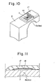
- Fig. 10 is a perspective view illustrating a principal portion of a load cell of a fifth embodiment of the present invention;
- Fig. 11 is an enlarged sectional view illustrating a principal portion of the fifth embodiment of the present invention;
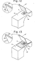
- Figs. 12, 13 and 14 are perspective views illustrating a principal portion of sixth, seventh and - eighth embodiments of a load cell according to the present invention;
- Fig. 15 is a front view illustrating a ninth embodiment of a load cell according to the present invention;
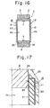
- Fig. 16 is a longitudinal sectional view taken along line XVI - XVI of Fig. 15;
- Fig. 17 is an enlarged view illustrating a principal portion of the load cell shown in Fig. 16;
- Fig. 18 is a front view illustrating a tenth embodiment of a load cell according to the present invention;
- Fig. 19 is a plan view illustrating the load cell of Fig. 18;
- Fig. 20 is an enlarged sectional view taken along line XX-XX of Fig. 18; and
- Fig. 21 is a front view illustrating an llth embodiment of a load cell according to the present invention.
- In the description that follows, a film obtained by providing one surface of a film substrate with a layer of deposited aluminum will be referred to as a "deposited aluminum film", while a film obtained by coating this deposited aluminum film beforehand with an adhesive will be referred to as a "deposited aluminum tape".
- In Fig. 1, numeral 1 denotes a load cell mounted by brackets C, D betweeen a scale body A and a weighing platform B provided thereon. A load-
sensitive element 2 constitutes the main body of the load cell 1 and is the element which develops strain when subjected to an applied load. As shown in Fig. 2, the load-sensitive element 2 has a hollow, quadrilateral configuration and comprises a rigid, fixedportion 3 at one extremity of the quadrilateral which is fixedly secured to the scale body A by the bracket C, a rigid,movable portion 4 at the other extremity of the quadrilateral to which the weighing platform B is affixed by the bracket D, and upper andlower beams rigid portions upper beam 5 is provided at two locations withflexible portions 5b formed by reducing the thickness of the beam by the formation of semicircular cut-outs 5a on the inner side thereof. Likewise, thelower beam 6 is provided at two locations withflexible portions 6b formed by reducing the thickness of the beam by the formation of semicircular cut-outs 6a on the inner side thereof. Astrain gauge 7 is bonded to the outer surface of each flexible portion. - The upper and
lower beams strain gauges 7 are bonded. A depositedaluminum film 8 is bonded to each of these surfaces 5', 6' so as to cover therespective strain gauge 7. As shown in Figs. 3 and 4, thefilm 8 comprises a film substrate 9 made of polyester or the like, and a non-porous depositedaluminum layer 10 formed on one suface of the film substrate 9 by a vapor deposition technique. This depositedaluminum film 8 is bonded to each of the bonding surfaces 5', 6' of the upper andlower beams aluminum film 8 is bonded into position, the entirety of the load-sensitive element 2 may be coated with asilicone rubber layer 12, as shown in Fig. 4. This is accomplished by first subjecting the element to a primer treatment to improve the adherence of the silicone rubber layer thereto, and then dipping the element into a silicone rubber solution. - When an article to be weighed is placed on the weighing platform B of the scale shown in Fig. 1, the
movable portion 4 of the load-sensitive element 2 constituting the load cell 1 is displaced downwardly owing to the applied load. With such downward displacement, the surfaces at which thestrain gauges 7 are bonded to theflexible portions lower beams sensitive element 2, which strain corresponds to the weight of the article on the weighing platform, may be detected through electrical means. - As described above, the deposited
aluminum film 8 is bonded over thestrain gauges 7, so that each strain gauge is covered by the non-porous depositedaluminum layer 10 constituting the film. Owing to the waterproof and moistureproof properties of the depositedaluminum layer 10, protection of the strain gauges against moisture and humidity is assured even if the scale is employed in an extremely wet or humid environment. Since the substrate 9 and depositedaluminum layer 10 constituting thefilm 8 exhibit sufficient flexibility and elasticity, thefilm 8 will not impede the deformation of the load-sensitive element 2 when a load is applied thereto. - Reference will now be had to Figs. 5 and 6 to describe a second embodiment of the present invention. In this embodiment, the deposited
aluminum film 8 of the first embodiment is replaced by a deposited aluminum tape 8'. The tape 8' comprises a substrate 91 made of polyester or the like, and a deposited aluminum layer 10' provided on one surface of the substrate 9'. Further, an acrylic or like adhesive 11' is applied in advance to the exposed surface of the deposited aluminum layer 10', namely to the side thereof opposite the substrate 9'. - According to this embodiment of the invention, the deposited aluminum tape 8' is bonded directly, by virtue of the adhesive 11', to the strain gauge bonding . surfaces 5', 6' on the
beams sensitive element 2. This makes it possible to dispense with the operation of applying the adhesive 11 to the load-sensitive element 2 of the first embodiment, as illustrated in Figs. 3 and 4. In the second embodiment of Figs. 5 and 6, a Kapton adhesive tape 13' ( "Kapton" is a trademark, it is manufactured by duPont) is applied to the electrically exposedconnections 7a of thestrain gauge 7 for the purpose of insulating the connections from the deposited aluminum layer 10', which is electrically conductive. - A third embodiment of the invention is illustrated in Figs. 7 and 8. After the
strain gauge 7 is bonded to thebeam 5 of the load-sensitive element 2, the strain gauge bonding surface 5' is subjected to an aluminum vapor deposition treatment to coat thestrain gauge 7 with a depositedaluminum layer 10". In accordance with this embodiment, the layers consisting of the film substrate 9 and adhesive 11 or 11' of the first and second embodiments are not interposed between the bonding surface 5' of the load-sensitive element 2 and the depositedaluminum layer 10". Instead, thestrain gauge 7 is directly coated with the depositedaluminum layer 10" to improve the adherence between thelayer 10" and both the strain gauge and strain gauge bonding surface. This provides thestrain gauge 7 with even greater protection against moisture and humidity. In order to insulate theconnections 7a of thestrain gauge 7 from the depositedaluminum layer 10", a strip of Kaptonadhesive tape 13" is applied to these connections. It is also necessary to prevent aluminum molecules from penetrating a paper covering thegrid 7b of thestrain gauge 7. To this end, apolyurethane coating 14" is applied to thegrid 7b before carrying out the aluminum deposition treatment. - Fig. 9 illustrates a fourth embodiment of the present invention. In the first embodiment of Figs. 2 through 4 and the second embodiment of Figs. 5 and 6, a discontinuous or step-like portion susceptible to the penetration of humidity may be formed where the deposited aluminum layer 10 (10') meets the surface of the load-
sensitive element 2 along the edge of the depositedaluminum film 8 or deposited aluminum tape 8'. This embodiment seeks to improve upon the foregoing arrangement by forming a deposited aluminum layer 15''' extending from the edge portion 8a''' of the deposited aluminum film (or deposited aluminum tape) 8''' to the surface of the load-sensitive element 2. The layer 15''' is formed by an aluminum vapor deposition treatment. The deposited aluminum layer 15''' closes off the portion of discontinuity between the aluminum deposited layer 10''' and the surface of the load-sensitive element 2. - It should be noted that the entirety of the load-
sensitive element 2 in the second, third and fourth embodiments of Figs. 6, 8 and 9 may be coated with asilicone rubber layer 12', 12", 12"', respectively, as described earlier in connection with the first embodiment shown in Fig. 4. - Thus, in accordance with the first through fourth embodiments of the present invention, a strain gauge bonded to the flexible portion of a load-sensitive element constituting a load cell is covered with a deposited aluminum layer. The strain gauge is therefore protected against moisture and humidity without any deleterious effect upon the load-strain characteristic of the load-sensitive element. The latter obtains from the fact that covering body offers little restraint to the deformation of the load-sensitive element. The result is a load cell having excellent performance and durability and, hence, a load cell suited for use in scales employed in extremely moist or humid environments.
- A fifth embodiment of the present invention will now be described with reference to Figs. 10 and 11. As shown, the
strain gauge 7 is covered with aTeflon sheet 16, which is in turn coated completely, by a process such as painting or dipping, with a coveringmember 17 such as silicone rubber, butyl or polyurethane. Thus, theTeflon sheet 16 is merely laid upon thestrain gauge 7 non-adhesively, that is, without the use of an adhesive, and is fixed to the surface of the load-sensitive element 2 by the coveringmember 17 applied thereto. - According to the arrangement of Figs. 10 and 11, the
strain gauge 7 bonded to the surface of the load-sensitive element 2 at theflexible portion 5b (6b) is protected against moisture and humidity by the coveringmember 17. TheTeflon sheet 16 is interposed between thestrain gauge 7 and the coveringmember 17, without being adhered to the strain gauge, so that thestrain gauge 7 is bonded solely to the load-sensitive element 2. - When an article to be weighed is placed on the weighing platform B of the scale shown in Fig. 1, the
movable portion 4 of the load-sensitive element 2 is displaced downwardly owing to the applied load. With such downward displacement, the surfaces at which thestrain gauges 7 are bonded to theflexible portions lower beams member 17, so that the strain gauges are free to stretch and relax and, hence, follow up the tension and compression of theflexible portions sensitive element 2,,namely the weight of the article on the weighing platform B, may be detected with great accuracy in the form of an electrical output from the strain gauges. - Sixth, seventh and eighth embodiments of the present invention are illustrated in Figs. 12, 13 and 14, respectively. In the sixth embodiment of Fig. 12, a deposited
aluminum tape 171 is used in place of the coating of silicone rubber or the like used as the covering member in the fifth embodiment described above. The deposited aluminum tape 17' comprises a substrate 17a' made of polyester or the like, and a deposited aluminum layer 17b' provided on one surface of the substrate 17a'. Further, an acrylic or like adhesive 17c' is applied in advance to the opposite side of the substrate 17a'. After eachstrain gauge 7 bonded to the surface of the load-sensitive element 2 at the flexible portions thereof is covered non-adhesively with theTeflon sheet 16, the foregoing deposited aluminum tape 17' is applied thereto and bonded to the surface of the load-sensitive element. It should be noted that the deposited aluminum tape 17' may be substituted by a deposited aluminum tape comprising the substrate 17a', the deposited aluminum layer 17b' provided on one surface of the substrate 17a, and the adhesive 17c' applied in advance to the exposed surface of the deposited aluminum layer 17b', rather than to the surface of the substrate 17a' opposite the deposited aluminum layer 17b'. - In the seventh embodiment of Fig. 13, a deposited
aluminum film 17" is employed as the covering member. The depositedaluminum film 17" comprises a substrate 17a", and a deposited aluminum layer 17b" provided on one surface of the substrate 17a". Thestrain gauge 7 is covered non-adhesively with theTeflon sheet 16, the upper surface and periphery whereof are coated with an adhesive 18. The depositedaluminum film 17" is bonded to the adhesive 18. - In the eighth embodiment of Fig. 14, aluminum foil 17''' is used as the covering member. As in the seventh embodiment of Fig. 13, the
strain gauge 7 is covered with theTeflon sheet 16, and the aluminum foil 17''' is bonded to the load-sensitive element 2 by the adhesive 18 so as to cover theTeflon sheet 16. - In each of the embodiments of Figs. 12 through 14, the deposited aluminum layers 17b', 17b", or the
aluminum foil 17"', protect thestrain gauge 7 against moisture and humidity. Like the embodiment shown in Figs. 10 and 11, theTeflon sheet 8 is interposed between thestrain gauge 7 and the coveringmember 17',17",17''', allowing the strain gauge to follow up the deformation of the load-sensitive element 2 in a highly precise manner. - Thus, in accordance with the fifth through eighth embodiments of the present invention, a strain gauge bonded to the flexible portion of a load-sensitive element constituting a load cell is covered with a covering member through the intermediary of a Teflon sheet placed on the strain gauge but not adhered thereto. The strain gauge is therefore protected against moisture and humidity, and the covering material will not restrict or constrain the stretching and relaxation of the strain gauge as it follows up the deformation of the load-sensitive element. This provides a load cell which exhibits excellent performance and weighing accuracy, and which is suited for use in scales employed in extremely moist or humid environments.
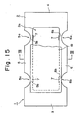
- Reference will now be had to Figs. 15 through 17 to describe a ninth embodiment of the present invention.
- As shown in Fig. 15, the load-
sensitive element 2 has a hollow, quadrilateral configuration and comprises a rigid, -fixedportion 3 at one extremity of the quadrilateral which is fixedly secured to the scale body A by the bracket C, a rigid,movable portion 4 at the other extremity of the quadrilateral to which the weighing platform B is affixed by the bracket D, and upper andlower beams rigid portions upper beam 5 is provided at two locations withflexible portions 5b formed by reducing the thickness of the beam by the formation of semicircular cut-outs 5a. Likewise, thelower beam 6 is provided at two locations withflexible portions 6b formed by reducing the thickness of the beam by the formation of semicircular cut-outs 6a. Astrain gauge 7 is bonded to the load-sensitive element 2 at each flexible portion thereof. In this embodiment of the invention, the cut-outs lower beams strain gauges 7 are bonded to the inner sides of the upper andlower beams hollow portion 2a of the load-sensitive element 2, rather than to the outer sides thereof as in the embodiments described above.Numeral 19 denotes a covering body which, as shown in Fig. 16, is bonded to eachside surface 2b of the load-sensitive element 2 so as to seal off thehollow portion 2a of the load-sensitive element. As shown in the enlarged view of Fig. 17, the coveringbody 19 comprises arubber sheet 21 bonded to theside surface 2b of the load-sensitive element 2 through asealant 20, andaluminum foil 22 bonded in place by the adhesive 11 so as to cover therubber sheet 10 from the outside. Thus, thestrain gauges 7 are covered while a space (thehollow portion 2a of the load-sensitive body 2) is provided around them. A silicone sealing material is suitable for use as thesealant 20, and an acrylic adhesive is suitable for use as the adhesive 11. A suitable material for use as therubber sheet 21 is butyl rubber in view of the flexibility thereof. After the coveringbody 19 is bonded in place, the entirety of the load-sensitive element 2 may be coated with asilicone rubber layer 23, as shown in Fig. 17. This is accomplished by first subjecting the element to a primer treatment, and then dipping the element into a silicone rubber solution. - When an article to be weighed is placed on the weighing platform B of the scale shown in Fig. 1, the
movable portion 4 of the load-sensitive element 2 constituting the load cell 1 is displaced downwardly owing to the applied load. With such downward displacement, the surfaces at which thestrain gauges 7 are bonded to theflexible portions lower beams sensitive element 2, which strain corresponds to the weight of the article on the weighing platform, may be detected through electrical means. - As described above, the
strain gauges 7 of the load cell 1 are covered with the coveringbody 19, which comprises therubber sheet 21 bonded to theside surface 2b of the load-sensitive element 2, and thealuminum foil 22. Owing to the waterproof and moistureproof properties of ·thealuminum foil 22, protection of the strain gauges against moisture and humidity is assured even if the scale is employed in an extremely wet or humid environment. Though thealuminum foil 22 lacks stretchability, deformation of the load-sensitive element 2 is in no way hampered because of the highlyflexible rubber sheet 21 interposed between thefoil 22 and the load-sensitive body 2. Further, since thestrain gauges 7 are covered by means of the coveringbodies 19 while thespace 2a is provided around them, the covering bodies do not adversely affect the creep characteristic. Thus, thestrain gauges 7 may'stretch and relax in excellent conformance with the stetching and relaxation of the strain gauge bonding surfaces located at theflexible portions sensitive element 2. With the arrangement of the invention, thestrain gauges 7 can be protected against moisture and humidity without any deterioration in the load-strain characteristic of the load-sensitive element 2 or in the creep characteristic of the strain gauges being caused by a restraining forced imposed by the coveringbodies 19. - A tenth embodiment of the present invention will now be described with reference to Figs. 18 through 20. This embodiment relates to a load cell 1 having
strain gauges 7 bonded to the outer sides of upper andlower beams sensitive element 2. Eachstrain gauge 7 is covered with a coveringbody 24. As shown in Fig. 20, each coveringbody 24 comprises arubber sheet 26 bonded to the surface of the load-sensitive element 2 by asealant 25, andaluminum foil 28 bonded in place by an adhesive 27 so as to cover the rubber sheet from the outside. Therubber sheet 26 has anopening 26a and is bonded to the load-sensitive element 2 in such a manner that thestrain gauge 7 will be situated in said opening. - In the present embodiment, each
strain gauge 7 is covered with thealuminum foil 28 bonded in place through the intermediary of therubber sheet 26, which is interposed between the load-sensitive body 2 and the aluminum foil, a space.(thehollow portion 10a') being provided around the strain gauges. Thus, as in the ninth embodiment, the strain gauges are protected against moisture and humidity without any adverse effect upon the load-strain characteristic of the load-sensitive body or the creep characteristic of the strain gauges. Also, the entirety of the load-sensitive element 2 may be coated with asilicone rubber layer 29, as shown in Fig. 20. - Reference will now be had to Fig. 21 to describe an llth embodiment of the present invention. This embodiment relates to a load cell 1 having
strain gauges 7 bonded to the inner sides of upper andlower beams sensitive element 2, namely the sides of the beams facing thehollow portion 2a of the load-sensitive body 2. As in the tenth embodiment of Figs. 18 through 20, eachstrain gauge 7 is covered . with a coveringbody 24 which comprises arubber sheet 26 bonded to the inner surface of the load-sensitive element 2 by a sealant, andaluminum foil 28 bonded in place by an adhesive so as to cover the rubber sheet from the outside. Therubber sheet 26 has anopening 26a and is bonded to the load-sensitive element 2 in such a manner that thestrain gauge 7 will be situated in said opening. - In the present embodiment, each
strain gauge 7 is covered with the-aluminum foil 28 bonded in place through the intermediary of therubber sheet 26, which is interposed between the load-sensitive body 2 and the aluminum foil, a space (thehollow portion 26a) being provided around the strain gauges. Thus, as in the foregoing embodiments, the strain gauges are protected against moisture and humidity without any adverse effect upon the load-strain characteristic of the load-sensitive body or the creep characteristic of the strain gauges. Also, the entirety of the load-sensitive element 2 may be coated with a silicone rubber layer. - It should be noted that the aluminum foils 22, 28 in the foregoing embodiments may be substituted by a deposited aluminum film comprising a substrate consisting primarily of polyester or the like, and a thin layer of aluminum formed on the surface of the substrate by vapor deposition.
- Thus, in all these examples a strain gauge is bonded to the flexible portions of the upper and lower beams of a load-sensitive element constituting a load cell, and each strain gauge is covered with aluminum foil or a deposited aluminum film bonded in place through the intermediary of a rubber sheet interposed between the load-sensitive element and the foil or film, a space being provided around the strain gauges. The strain gauges are thus effectively protected against moisture and humidity without any adverse effect upon the load-strain characteristic of the load-sensitive element or the creep characteristic of the strain gauges. The result is a load cell having excellent performance and durability and, hence, a load cell suited for use in scales employed in extremely moist or humid environments.
Claims (12)
Applications Claiming Priority (6)
| Application Number | Priority Date | Filing Date | Title |
|---|---|---|---|
| JP16184082U JPS5966127U (en) | 1982-10-26 | 1982-10-26 | load cell |
| JP187744/82 | 1982-10-26 | ||
| JP161840/82U | 1982-10-26 | ||
| JP18774482A JPS5977325A (en) | 1982-10-26 | 1982-10-26 | Load cell |
| JP198259/82 | 1982-11-10 | ||
| JP19825982A JPS5987331A (en) | 1982-11-10 | 1982-11-10 | Load cell |
Publications (4)
| Publication Number | Publication Date |
|---|---|
| EP0107966A2 true EP0107966A2 (en) | 1984-05-09 |
| EP0107966A3 EP0107966A3 (en) | 1986-01-15 |
| EP0107966B1 EP0107966B1 (en) | 1988-10-05 |
| EP0107966B2 EP0107966B2 (en) | 1991-12-27 |
Family
ID=27321916
Family Applications (1)
| Application Number | Title | Priority Date | Filing Date |
|---|---|---|---|
| EP83306472A Expired EP0107966B2 (en) | 1982-10-26 | 1983-10-25 | Load cell and method for its manufacture |
Country Status (4)
| Country | Link |
|---|---|
| US (1) | US4557150A (en) |
| EP (1) | EP0107966B2 (en) |
| AU (1) | AU547838B2 (en) |
| DE (1) | DE3378167D1 (en) |
Cited By (5)
| Publication number | Priority date | Publication date | Assignee | Title |
|---|---|---|---|---|
| EP0399466A3 (en) * | 1989-05-24 | 1992-01-15 | Ishida Scales Mfg. Co., Ltd. | Load cell |
| EP0671609A1 (en) * | 1994-03-09 | 1995-09-13 | ISHIDA CO., Ltd. | Load sensor |
| EP0667514A3 (en) * | 1994-02-15 | 1996-09-04 | Hottinger Messtechnik Baldwin | Method for manufacturing strain-gauges. |
| US5712432A (en) * | 1995-07-07 | 1998-01-27 | Hottinger Baldwin Messtechnik Gmbh | Pin load cell for weighing |
| EP1384980A1 (en) * | 2002-07-25 | 2004-01-28 | Mettler-Toledo GmbH | Moisture protection for an electromechanical transducer |
Families Citing this family (13)
| Publication number | Priority date | Publication date | Assignee | Title |
|---|---|---|---|---|
| US4718287A (en) * | 1985-05-07 | 1988-01-12 | Esselte Moreau | Force sensing device for measurement apparatus |
| US4821583A (en) * | 1987-07-14 | 1989-04-18 | E. I. Du Pont De Nemours And Company | Tension measuring apparatus |
| DE4015666A1 (en) * | 1990-05-16 | 1991-11-28 | Deutsche Forsch Luft Raumfahrt | Protecting expansion strips used to monitor force in recording arm - by coating with layer which stops condensed air from corroding the strips |
| FR2701317B1 (en) * | 1993-02-09 | 1995-03-31 | Thomson Csf | Device for measuring the forces exerted on a mechanical part and fixing method. |
| FI105721B (en) * | 1995-09-15 | 2000-09-29 | Vesa Koivisto | Sensors for measuring loads |
| ITPV20010009A1 (en) * | 2001-10-10 | 2003-04-10 | Francesco Ramaioli | SINGLE SENSOR FOR MEASUREMENT OF SPEED AND WIND DIRECTION, WITHOUT MOVING PARTS |
| DE60112953T2 (en) * | 2001-12-15 | 2006-06-29 | S.C.A.I.M.E. S.A. | transducer |
| US20040183648A1 (en) * | 2003-03-21 | 2004-09-23 | Weber Thomas E. | Strain sensors and housings and circuit boards with integrated strain sensors |
| US20060116247A1 (en) * | 2004-12-01 | 2006-06-01 | Precor, Inc. | Total body elliptical exercise equipment with upper body monitoring |
| CA2685610C (en) * | 2007-05-02 | 2015-02-03 | Flexco Industries Inc. | Sensor device to monitor deformation in structural members, such as solid structures |
| TWI468199B (en) * | 2012-07-26 | 2015-01-11 | Joong Chenn Industry Co Ltd | Weight training device with load detection system |
| KR102120960B1 (en) * | 2014-07-17 | 2020-06-09 | 삼성전자주식회사 | A supporting frame and a motion assistance apparatus comprising thereof |
| EP3617683A1 (en) | 2018-08-31 | 2020-03-04 | Mettler Toledo (Changzhou) Precision Instrument Ltd. | Method of insulating a strain gauge against moisture penetration |
Family Cites Families (6)
| Publication number | Priority date | Publication date | Assignee | Title |
|---|---|---|---|---|
| US3089107A (en) * | 1961-04-14 | 1963-05-07 | Iii Mills Dean | Waterproofing strain gages |
| US3639875A (en) * | 1970-08-24 | 1972-02-01 | Brewer Engineering Lab Inc | Strain gage assembly and method of attachment |
| US3863192A (en) * | 1973-01-24 | 1975-01-28 | Irving R Grey | Waterproof mechanically protected sensor package and method of installation |
| DE2728916A1 (en) * | 1977-06-27 | 1979-01-18 | Hottinger Messtechnik Baldwin | METHOD AND DEVICE FOR COVERING A STRAIN GAUGE |
| JPS55140112A (en) * | 1979-04-19 | 1980-11-01 | Tokyo Electric Co Ltd | Weighing device employing load cell |
| DE3043139C2 (en) * | 1980-11-15 | 1985-08-08 | Bizerba-Werke Wilhelm Kraut Kg, 7460 Balingen | Electromechanical bending force transducer, in particular for load cells |
-
1983
- 1983-10-25 EP EP83306472A patent/EP0107966B2/en not_active Expired
- 1983-10-25 AU AU20562/83A patent/AU547838B2/en not_active Ceased
- 1983-10-25 DE DE8383306472T patent/DE3378167D1/en not_active Expired
- 1983-10-26 US US06/545,473 patent/US4557150A/en not_active Expired - Fee Related
Non-Patent Citations (1)
| Title |
|---|
| None |
Cited By (8)
| Publication number | Priority date | Publication date | Assignee | Title |
|---|---|---|---|---|
| EP0399466A3 (en) * | 1989-05-24 | 1992-01-15 | Ishida Scales Mfg. Co., Ltd. | Load cell |
| EP0667514A3 (en) * | 1994-02-15 | 1996-09-04 | Hottinger Messtechnik Baldwin | Method for manufacturing strain-gauges. |
| EP0671609A1 (en) * | 1994-03-09 | 1995-09-13 | ISHIDA CO., Ltd. | Load sensor |
| US5712432A (en) * | 1995-07-07 | 1998-01-27 | Hottinger Baldwin Messtechnik Gmbh | Pin load cell for weighing |
| EP1384980A1 (en) * | 2002-07-25 | 2004-01-28 | Mettler-Toledo GmbH | Moisture protection for an electromechanical transducer |
| WO2004011892A1 (en) * | 2002-07-25 | 2004-02-05 | Mettler-Toledo Gmbh | Moisture protection for an electromechanical converter |
| EP1686356A3 (en) * | 2002-07-25 | 2006-08-09 | Mettler-Toledo GmbH | Moisture protection for an electromechanical transducer |
| US7197940B2 (en) | 2002-07-25 | 2007-04-03 | Mettler-Toledo Ag | Moisture protection for an electromechanical transducer |
Also Published As
| Publication number | Publication date |
|---|---|
| US4557150A (en) | 1985-12-10 |
| AU547838B2 (en) | 1985-11-07 |
| AU2056283A (en) | 1984-05-03 |
| EP0107966B1 (en) | 1988-10-05 |
| DE3378167D1 (en) | 1988-11-10 |
| EP0107966A3 (en) | 1986-01-15 |
| EP0107966B2 (en) | 1991-12-27 |
Similar Documents
| Publication | Publication Date | Title |
|---|---|---|
| EP0107966B1 (en) | Load cell and method for its manufacture | |
| US5631622A (en) | Strain gage and measuring transducer and method of producing the same | |
| US4343197A (en) | Load-cell balance | |
| US5052505A (en) | Load cell | |
| US3935485A (en) | Piezoelectric key board switch | |
| US5404124A (en) | Foil strain gage and load cell with such a strain gage | |
| US4823605A (en) | Semiconductor pressure sensor with casing and method for its manufacture | |
| US4437138A (en) | Force sensing means and method of producing such sensing means | |
| US6085596A (en) | Pressure sensor having an insulating layer and fluid tight amorphous metal layer | |
| US4307371A (en) | Method and apparatus for covering a foil strain gauge | |
| US20230123737A1 (en) | Biological sensor | |
| CH669259A5 (en) | ELECTRIC THICK FILM DEFORMATION SENSOR, ESPECIALLY PRESSURE SENSOR. | |
| ES8204172A1 (en) | Pyroelectric detector. | |
| JPH07113697A (en) | Load cell | |
| JPH0220046B2 (en) | ||
| JPS6237149Y2 (en) | ||
| US4685526A (en) | Arrangement in a load cell | |
| JPS5987331A (en) | Load cell | |
| JPH03251704A (en) | Manufacture of strain gauge | |
| JPH0350434Y2 (en) | ||
| JPH0528947U (en) | Load cell | |
| JPS61132831A (en) | Load cell | |
| FR2646309B1 (en) | METHOD FOR MANUFACTURING AN ACOUSTIC SENSOR AND ACOUSTIC SENSOR THUS OBTAINED, WITH A PROTECTIVE LAYER | |
| JPS6449925A (en) | Moistureproof structure of strain gage type load cell | |
| JPH04274720A (en) | Strain gauge-type load cell |
Legal Events
| Date | Code | Title | Description |
|---|---|---|---|
| PUAI | Public reference made under article 153(3) epc to a published international application that has entered the european phase |
Free format text: ORIGINAL CODE: 0009012 |
|
| AK | Designated contracting states |
Designated state(s): BE DE GB NL SE |
|
| PUAL | Search report despatched |
Free format text: ORIGINAL CODE: 0009013 |
|
| AK | Designated contracting states |
Designated state(s): BE DE GB NL SE |
|
| 17P | Request for examination filed |
Effective date: 19860613 |
|
| 17Q | First examination report despatched |
Effective date: 19870817 |
|
| GRAA | (expected) grant |
Free format text: ORIGINAL CODE: 0009210 |
|
| AK | Designated contracting states |
Kind code of ref document: B1 Designated state(s): BE DE GB NL SE |
|
| PG25 | Lapsed in a contracting state [announced via postgrant information from national office to epo] |
Ref country code: BE Effective date: 19881005 |
|
| REF | Corresponds to: |
Ref document number: 3378167 Country of ref document: DE Date of ref document: 19881110 |
|
| PLBI | Opposition filed |
Free format text: ORIGINAL CODE: 0009260 |
|
| 26 | Opposition filed |
Opponent name: HOTTINGER BALDWIN MESSTECHNIK GMBH PATENTABTEILUNG Effective date: 19890701 |
|
| PGFP | Annual fee paid to national office [announced via postgrant information from national office to epo] |
Ref country code: SE Payment date: 19891010 Year of fee payment: 7 |
|
| PGFP | Annual fee paid to national office [announced via postgrant information from national office to epo] |
Ref country code: NL Payment date: 19891031 Year of fee payment: 7 |
|
| NLR1 | Nl: opposition has been filed with the epo |
Opponent name: HOTTINGER BALDWIN MESSTECHNIK GMBH |
|
| BERE | Be: lapsed |
Owner name: K.K. ISHIDA KOKI SEISAKUSHO Effective date: 19891031 |
|
| PG25 | Lapsed in a contracting state [announced via postgrant information from national office to epo] |
Ref country code: SE Effective date: 19901026 |
|
| PG25 | Lapsed in a contracting state [announced via postgrant information from national office to epo] |
Ref country code: NL Effective date: 19910501 |
|
| NLV4 | Nl: lapsed or anulled due to non-payment of the annual fee | ||
| PUAH | Patent maintained in amended form |
Free format text: ORIGINAL CODE: 0009272 |
|
| STAA | Information on the status of an ep patent application or granted ep patent |
Free format text: STATUS: PATENT MAINTAINED AS AMENDED |
|
| 27A | Patent maintained in amended form |
Effective date: 19911227 |
|
| AK | Designated contracting states |
Kind code of ref document: B2 Designated state(s): BE DE GB NL SE |
|
| EUG | Se: european patent has lapsed |
Ref document number: 83306472.8 Effective date: 19910603 |
|
| PGFP | Annual fee paid to national office [announced via postgrant information from national office to epo] |
Ref country code: GB Payment date: 19951016 Year of fee payment: 13 |
|
| PG25 | Lapsed in a contracting state [announced via postgrant information from national office to epo] |
Ref country code: GB Effective date: 19961025 |
|
| GBPC | Gb: european patent ceased through non-payment of renewal fee |
Effective date: 19961025 |
|
| PGFP | Annual fee paid to national office [announced via postgrant information from national office to epo] |
Ref country code: DE Payment date: 19981103 Year of fee payment: 16 |
|
| PG25 | Lapsed in a contracting state [announced via postgrant information from national office to epo] |
Ref country code: DE Free format text: LAPSE BECAUSE OF NON-PAYMENT OF DUE FEES Effective date: 20000801 |