EP0107588A1 - Device for determining the stationary echo cancellation threshold, especially in a radar receiver - Google Patents
Device for determining the stationary echo cancellation threshold, especially in a radar receiver Download PDFInfo
- Publication number
- EP0107588A1 EP0107588A1 EP19830402023 EP83402023A EP0107588A1 EP 0107588 A1 EP0107588 A1 EP 0107588A1 EP 19830402023 EP19830402023 EP 19830402023 EP 83402023 A EP83402023 A EP 83402023A EP 0107588 A1 EP0107588 A1 EP 0107588A1
- Authority
- EP
- European Patent Office
- Prior art keywords
- log
- values
- hand
- receives
- calculating
- Prior art date
- Legal status (The legal status is an assumption and is not a legal conclusion. Google has not performed a legal analysis and makes no representation as to the accuracy of the status listed.)
- Withdrawn
Links
Images

Classifications
-
- G—PHYSICS
- G01—MEASURING; TESTING
- G01S—RADIO DIRECTION-FINDING; RADIO NAVIGATION; DETERMINING DISTANCE OR VELOCITY BY USE OF RADIO WAVES; LOCATING OR PRESENCE-DETECTING BY USE OF THE REFLECTION OR RERADIATION OF RADIO WAVES; ANALOGOUS ARRANGEMENTS USING OTHER WAVES
- G01S7/00—Details of systems according to groups G01S13/00, G01S15/00, G01S17/00
- G01S7/02—Details of systems according to groups G01S13/00, G01S15/00, G01S17/00 of systems according to group G01S13/00
- G01S7/28—Details of pulse systems
- G01S7/285—Receivers
- G01S7/292—Extracting wanted echo-signals
- G01S7/2923—Extracting wanted echo-signals based on data belonging to a number of consecutive radar periods
- G01S7/2927—Extracting wanted echo-signals based on data belonging to a number of consecutive radar periods by deriving and controlling a threshold value
-
- G—PHYSICS
- G01—MEASURING; TESTING
- G01S—RADIO DIRECTION-FINDING; RADIO NAVIGATION; DETERMINING DISTANCE OR VELOCITY BY USE OF RADIO WAVES; LOCATING OR PRESENCE-DETECTING BY USE OF THE REFLECTION OR RERADIATION OF RADIO WAVES; ANALOGOUS ARRANGEMENTS USING OTHER WAVES
- G01S13/00—Systems using the reflection or reradiation of radio waves, e.g. radar systems; Analogous systems using reflection or reradiation of waves whose nature or wavelength is irrelevant or unspecified
- G01S13/02—Systems using reflection of radio waves, e.g. primary radar systems; Analogous systems
- G01S13/50—Systems of measurement based on relative movement of target
- G01S13/52—Discriminating between fixed and moving objects or between objects moving at different speeds
- G01S13/538—Discriminating between fixed and moving objects or between objects moving at different speeds eliminating objects that have not moved between successive antenna scans, e.g. area MTi
Definitions
- the present invention relates to a device for determining the threshold for eliminating fixed echoes, in particular for a radar receiver.
- Fixed echoes are mainly due to the reflection of radar waves on the constituent elements of the landscape (clouds, sea, forests, ... etc). When these elements are agitated with light movements (for example during a gale), the echoes they reflect are no longer fixed but slowly moving, hence the need to eliminate slowly moving echoes in the same way as fixed echoes.
- Area Moving Target Indicator or more commonly “Area MTI”
- This technique which can be called elimination of fixed echoes by zones, consists in dividing the radar coverage into elementary cells, and in comparing, at each antenna turn, the signal received from each elementary cell with the signal received during the turn of 'previous antenna. If these two signals have identical or similar amplitudes, it is deduced therefrom that the elementary cell considered returns a fixed or slowly mobile echo. If these two signals have very different amplitudes, we deduce the passage of a moving target in this elementary cell.
- a more sophisticated technique consists in comparing the signal received at each antenna turn to a threshold established from the signals received during several previous antenna turns, in order to take into account the variations of the unwanted echoes (or clutter). It is known for example to establish this threshold by incrementing or decrementing the previously established threshold according to whether the amplitude of the received signal is greater or below this threshold.
- this threshold When the threshold is simply established by incrementation or decrementation, according to the amplitude of the signal received, of the previously established threshold, this threshold only reflects the average value of the amplitude of the clutter, but it does not take account of the fluctuations snapshots of the clutter amplitude around this mean value.
- the method consisting in adding or subtracting from the threshold thus obtained a determined value so as to keep a constant probability of false weapon for a given number of antenna turns makes it possible to follow the variations of the clutter, but on condition that they are sufficiently repetitive from one antenna turn to another. On the other hand, if the clutter variations are not sufficiently repetitive, this method does not make it possible to eliminate the corresponding echoes, and depending on the amplitude of these echoes, there is then a risk of false alarm.
- the subject of the present invention is a device for determining the threshold for eliminating fixed echoes making it possible to avoid these drawbacks by better adapting the threshold to fluctuations in the clutter, and in particular to non-repetitive fluctuations from one antenna turn to the other.
- the device for determining the threshold for eliminating fixed echoes by zones includes means for calculating the average value ⁇ of these echoes, and means for calculating their standard deviation ⁇ , the threshold being equal to y + K ⁇ , where K is a constant.
- the means for calculating the mean value and standard deviation are achieved in a particularly clever way using recursive digital filters operating on logarithmic values, which makes it possible to significantly reduce the number and size of the memories required.
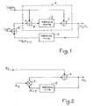
- FIG. 1 shows the means for calculating the mean value ⁇ .
- ⁇ i-1 the mean value of the amplitude of the echoes received for this zone during the antenna turns preceding the turn number i, and by ⁇ the mean value ⁇ i-1 updated using the signal incident.
- these calculation means operate on logarithmic values. This is particularly interesting in the case of the application to radars where, because of the significant dynamics of the echoes received, a linear processing would require a prohibitive number of binary elements.
- the means for calculating the average value constitute the transposition into the logarithmic domain of the recursive digital filter represented in FIG. 2.
- the recursive digital filter represented in FIG. 2 comprises, in a known manner, an adder 1 which receives on the one hand the incident signal e i , on the other hand the previous average value ⁇ i-1 from a random access memory 2, and multiplied by a coefficient K 1 (less than 1) using a multiplier 3, and which provides the new mean value ⁇ i .
- the calculation means represented in FIG. 1 likewise comprise an adder 1 and a random access memory 2.
- the multiplier 3 is replaced by an adder 3 'which receives the value log K 1 .
- a circuit 4 for calculating the logarithm of the sum of two values from the logarithms of these two values is also added with respect to FIG. 2.
- the circuit 4 consists of the adder 1 which receives on the one hand the signal log e i , on the other hand the output signal from a read only memory 5 which in turn receives the output signal from a subtractor 6 , the subtractor 6 receiving at its input + the output signal from the adder 3 ', and at its input - the signal log e i .
- the filter of Figure 2 provides a signal ⁇ i such that:
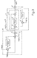
- FIG. 3 shows the means for calculating the standard deviation ⁇ .
- the variance ⁇ i 2 is the mean value of the square of the difference ⁇ i-1 - e i between the previous mean and the incident signal.
- the means for calculating the standard deviation operate on logarithmic values. They are also produced from a recursive digital filter 7, transposed in the logarithmic domain, at the input of which is applied the value log ( ⁇ i-1 - e i ) 2 supplied by a calculation circuit 8.
- the filter 7 consists of the same elements 1, 2, 3 ', 4 as the filter shown in Figure 1, arranged in the same way, except that the coefficient K 1 is replaced by a coefficient K 2 also less than 1 .
- the filter 7 calculates, from the value log ( ⁇ i-1 - e i ) 2 supplied by the circuit 8, the value log ⁇ i 2 equal to log (( ⁇ i-1 - e i ) 2 + K 2 ⁇ i 2 -1 ).
- Log ⁇ i is obtained at the output of a multiplier 12 ′ which receives on the one hand the output signal of the filter 7, on the other hand the coefficient 1/2.
- the calculation circuit 8 comprises a subtractor 9 which receives on its input + the incident signal log e. and on its input - the signal log ⁇ i-1 provided by the RAM 2 of FIG. 1, a read only memory 10 which receives the output signal from the adder 9, an adder 11 which receives on the one hand the signal readout output 10, on the other hand the signal log ⁇ i-1 , and a multiplier 12 which receives on the one hand the output signal of the adder 11, on the other hand the coefficient 2, and which provides the log signal ( ⁇ i-1 - e i ) 2 ⁇
- the calculation circuit 8 operates as follows.
- log can also be written log obtained from the log value obtained at the output of the subtractor 9, by correction with the aid of a properly programmed read-only memory 10.
- the value log ( ⁇ i-1 - e i ) 2 is then obtained at the output of the multiplier 12 placed at the output of the adder 11.
- the threshold to which the echo e i received during the antenna tour number i is compared is expressed in the form ⁇ i + K ⁇ i , where ⁇ i denotes the average value of the echoes received during the antenna tours preceding the turn number i, ⁇ i denotes their standard deviation, and K is a constant which is determined so as to have a given false alarm probability.
- the threshold determination device operates on logarithmic values and supplies the value log ( ⁇ i + K ⁇ i ) which will be compared with the value log e i .
- the value log ( ⁇ i + K ⁇ i ) is obtained from the values log ⁇ i and log K ⁇ i by means of a circuit for calculating the logarithm of the sum of two values from the logarithms of these two values, identical to circuit 4 of figure 1.
- the value log ⁇ i is available at the output of the circuit of figure 1.
- the value log K ⁇ i is obtained using an adder 13 which receives on the one hand the value Constant log K, on the other hand the signal log ⁇ i available at the output of the circuit of FIG. 3.
- the signal log e i is not sent as such to the means for calculating the standard deviation (FIG. 3), but after processing through a series of comparators 14.
- the passage of a moving target in the zone considered can lead under certain conditions (for example in the case of the passage of an aircraft in a clear zone) an increase in the standard deviation such as the threshold thus obtained. is greater than the echo reflected by this target. In this case, the rise in the standard deviation must therefore be limited.
- the increase in the standard deviation, and therefore the threshold, caused by the passage of the large plane can be sufficient to prevent detection of the small aircraft.
- the rise in standard deviation must be limited.
Abstract
Description
La présente invention concerne un dispositif de détermination du seuil d'élimination d'échos fixes, notamment pour récepteur radar.The present invention relates to a device for determining the threshold for eliminating fixed echoes, in particular for a radar receiver.
Dans un récepteur radar, et plus particulièrement dans un radar de surveillance, il est important de procéder à l'élimination des échos fixes ou lentement mobiles, afin de ne laisser subsister que les échos correspondant à des cibl es franchement mobiles.In a radar receiver, and more particularly in a surveillance radar, it is important to proceed with the elimination of fixed or slowly moving echoes, in order to leave only the echoes corresponding to frankly mobile targets.
Les échos fixes ou lentement mobiles sont en effet très visibles sur les consoles de visualisation et diminuent notablement le contraste et donc la détection.Fixed or slowly moving echoes are indeed very visible on display consoles and significantly reduce contrast and therefore detection.
Les échos fixes sont dus principalement à la réflexion des ondes radar sur les éléments constitutifs du paysage (nuages, mer, forêts, ...etc). Lorsque ces éléments sont agités de légers mouvements (par exemple lors d'un coup de vent), les échos qu'ils réfléchissent ne sont plus fixes mais lentement mobiles, d'où la nécessité d'éliminer les échos lentement mobiles au même titre que les échos fixes.Fixed echoes are mainly due to the reflection of radar waves on the constituent elements of the landscape (clouds, sea, forests, ... etc). When these elements are agitated with light movements (for example during a gale), the echoes they reflect are no longer fixed but slowly moving, hence the need to eliminate slowly moving echoes in the same way as fixed echoes.
Pour cela, il est connu d'utiliser la technique dite "Area Moving Target Indicator" (ou plus couramment "Area MTI"). Cette technique, qui peut être appelée élimination d'échos fixes par zones, consiste à diviser la couverture radar en cellules élémentaires , et à comparer, à chaque tour d'antenne, le signal reçu de chaque cellule élémentaire au signal reçu lors du tour d'antenne précédent. Si ces deux signaux ont des amplitudes identiques ou voisines, on en déduit que la cellule élémentaire considérée renvoit un écho fixe ou lentement mobile. Si ces deux signaux ont des amplitudes très différentes, on en déduit le passage d'une cible mobile dans cette cellule élémentaire.For this, it is known to use the technique called "Area Moving Target Indicator" (or more commonly "Area MTI"). This technique, which can be called elimination of fixed echoes by zones, consists in dividing the radar coverage into elementary cells, and in comparing, at each antenna turn, the signal received from each elementary cell with the signal received during the turn of 'previous antenna. If these two signals have identical or similar amplitudes, it is deduced therefrom that the elementary cell considered returns a fixed or slowly mobile echo. If these two signals have very different amplitudes, we deduce the passage of a moving target in this elementary cell.
Une technique plus perfectionnée consiste à comparer le signal reçu à chaque tour d'antenne à un seuil établi à partir des signaux reçus au cours de plusieurs tours d'antenne précédents, afin de prendre en compte les variations des échos indésirables (ou clutter). Il est connu par exemple d'établir ce seuil en incrémentant ou en décrémentant le seuil précédemment établi suivant que l'amplitude du signal reçu est supérieure ou inférieure à ce seuil.A more sophisticated technique consists in comparing the signal received at each antenna turn to a threshold established from the signals received during several previous antenna turns, in order to take into account the variations of the unwanted echoes (or clutter). It is known for example to establish this threshold by incrementing or decrementing the previously established threshold according to whether the amplitude of the received signal is greater or below this threshold.
Il est également connu, d'après la demande de brevet français N°2 234 571 déposée au nom de la demanderesse, de perfectionner cette dernière méthode en ajoutant ou en retranchant au seuil ainsi établi une valeur déterminée de manière à conserver une probabilité de fausse alarme constante pour un nombre de tours d'antenne donné.It is also known, from French patent application No. 2 234 571 filed in the name of the applicant, to perfect this latter method by adding or subtracting from the threshold thus established a value determined so as to retain a probability of false constant alarm for a given number of antenna turns.
Tous ces procédés de détermination du seuil d'élimination des échos indésirables ont pour inconvénient de ne pas être suffisamment adaptés aux fluctuations du clutter.All of these methods for determining the threshold for eliminating unwanted echoes have the drawback of not being sufficiently adapted to fluctuations in the clutter.
Lorsque le seuil est simplement établi par incrémentation ou décré- mentation, suivant l'amplitude du signal reçu, du seuil précédemment établi, ce seuil ne fait que refléter la valeur moyenne de l'amplitude du clutter, mais il ne tient aucun compte des fluctuations instantanées de l'amplitude du clutter autour de cette valeur moyenne.When the threshold is simply established by incrementation or decrementation, according to the amplitude of the signal received, of the previously established threshold, this threshold only reflects the average value of the amplitude of the clutter, but it does not take account of the fluctuations snapshots of the clutter amplitude around this mean value.
La méthode consistant à ajouter ou à retrancher au seuil ainsi obtenu une valeur déterminée de manière à conserver une probabilité de fausse al arme constante pour un nombre de tours d'antenne donné permet bien de suivre les variations du clutter, mais à condition qu'elles soient suffisamment répétitives d'un tour d'antenne à l'autre. En revanche, si les variations du clutter ne sont pas suffisamment répétitives, cette méthode ne permet pas d'éliminer les échos correspondants, et suivant l'amplitude de ces échos, il y a alors risque de fausse alarme.The method consisting in adding or subtracting from the threshold thus obtained a determined value so as to keep a constant probability of false weapon for a given number of antenna turns makes it possible to follow the variations of the clutter, but on condition that they are sufficiently repetitive from one antenna turn to another. On the other hand, if the clutter variations are not sufficiently repetitive, this method does not make it possible to eliminate the corresponding echoes, and depending on the amplitude of these echoes, there is then a risk of false alarm.
La présente invention a pour objet un dispositif de détermination du seuil d'élimination d'échos fixes permettant d'éviter ces inconvénients par une meilleure adaptation du seuil aux fluctuations du clutter, et notamment aux fluctuations non répétitives d'un tour d'antenne à l'autre.The subject of the present invention is a device for determining the threshold for eliminating fixed echoes making it possible to avoid these drawbacks by better adapting the threshold to fluctuations in the clutter, and in particular to non-repetitive fluctuations from one antenna turn to the other.
Selon l'invention, le dispositif de détermination du seuil d'élimination d'échos fixes par zones, notamment pour récepteur radar, dans lequel ce seuil est établi à chaque tour d'antenne, pour chaque zone, à partir des échos reçus pour cette zone lors des tours d'antenne précédents, comporte des moyens pour calculer la valeur moyenne µ de ces échos, et des moyens pour calculer leur écart type σ, le seuil étant égal à y + K σ, où K est une constante.According to the invention, the device for determining the threshold for eliminating fixed echoes by zones, in particular for a radar receiver, in which this threshold is established at each antenna turn, for each zone, on the basis of the echoes received for this zone during previous antenna turns, includes means for calculating the average value µ of these echoes, and means for calculating their standard deviation σ, the threshold being equal to y + K σ, where K is a constant.
Suivant un autre aspect de l'invention, les moyens de calcul de la valeur moyennne et de l'écart type sont réalisés de manière particulièrement astucieuse à l'aide de filtres numériques récursifs opérant sur des valeurs logarithmiques, ce qui permet de réduire sensiblement le nombre et la taille des mémoires nécessaires.According to another aspect of the invention, the means for calculating the mean value and standard deviation are achieved in a particularly clever way using recursive digital filters operating on logarithmic values, which makes it possible to significantly reduce the number and size of the memories required.
Les objets et caractéristiques de la présente invention apparaîtront plus clairement à l'aide de la description suivante d'exemples de réalisation, ladite description étant faite en relation avec les dessins ci- annexés dans lequels :
- - la figure 1 représente les moyens de calcul de la valeur moyenne utilisés dans le dispositif suivant l'invention.
- - la figure 2 représente un filtre numérique récursif utilisé selon l'art connu pour le calcul d'une valeur moyenne.
- - la figure 3 représente les moyens de calcul de l'écart type utilisés dans le dispositif suivant l'invention.
- - la figure 4 représente le dispositif de détermination de seuil suivant l'invention.
- - Figure 1 shows the means of calculating the average value used in the device according to the invention.
- - Figure 2 shows a recursive digital filter used according to the known art for the calculation of an average value.
- - Figure 3 shows the means of calculating the standard deviation used in the device according to the invention.
- - Figure 4 shows the threshold determination device according to the invention.
Sur ces différentes figures, des éléments identiques portent les mêmes références.In these different figures, identical elements have the same references.
Sur la figure 1 on a représenté les moyens de calcul de la valeur moyenne µ.FIG. 1 shows the means for calculating the mean value µ.
On désigne par e. l'écho reçu pour une zone donnée de la couverture radar, lors du tour d'antenne numéro i.We denote by e. the echo received for a given area of radar coverage, during antenna tour number i.
On désigne par µi-1 la valeur moyenne de l'amplitude des échos reçus pour cette zone au cours des tours d'antenne précédant le tour numéro i, et par µ la valeur moyenne µi-1 réactualisée à l'aide du signal incident e..We denote by µ i-1 the mean value of the amplitude of the echoes received for this zone during the antenna turns preceding the turn number i, and by µ the mean value µ i-1 updated using the signal incident..
Pour réduire le nombre d'éléments binaires nécessaires au calcul, ces moyens de calcul opèrent sur des valeurs logarithmiques. Ceci est particulièrement intéressant dans le cas de l'application aux radars où, du fait de la dynamique importante des échos reçus, un traitement linéaire nécessiterait un nombre d'éléments binaires prohibitif.To reduce the number of binary elements required for the calculation, these calculation means operate on logarithmic values. This is particularly interesting in the case of the application to radars where, because of the significant dynamics of the echoes received, a linear processing would require a prohibitive number of binary elements.
Les moyens de calcul de la valeur moyenne constituent la transposition dans le domaine logarithmique du filtre numérique récursif représenté sur la figure 2.The means for calculating the average value constitute the transposition into the logarithmic domain of the recursive digital filter represented in FIG. 2.
Le filtre numérique récursif représenté sur la figure 2 comporte, de manière connue, un additionneur 1 qui reçoit d'une part le signal incident ei, d'autre part la valeur moyenne précédente µi-1 issue d'une mémoire vive 2, et multipliée par un coefficient K1 (inférieur à 1) grâce à un multiplieur 3, et qui fournit la nouvelle valeur moyenne µi.The recursive digital filter represented in FIG. 2 comprises, in a known manner, an
Les moyens de calcul représentés sur la figure 1 comportent de la même façon un additionneur 1 et une mémoire vive 2. Le multiplieur 3 est remplacé par un additionneur 3' qui reçoit la valeur log K1.The calculation means represented in FIG. 1 likewise comprise an
Un circuit 4 de calcul du logarithme de la somme de deux valeurs à partir des logarithmes de ces deux valeurs est également rajouté par rapport à la figure 2.A
Le circuit 4 est constitué de l'additionneur 1 qui reçoit d'une part le signal log ei, d'autre part le signal de sortie d'une mémoire morte 5 qui reçoit à son tour le signal de sortie d'un soustracteur 6, le soustracteur 6 recevant sur son entrée + le signal de sortie de l'additionneur 3', et sur son entrée - le signal log ei.The
On explique maintenant le fonctionnement du circuit 4.We now explain the operation of
Le filtre de la figure 2 fournit un signal µi tel que :![]()
![]()
On peut écrire :
On a:![]()
![]()
On observe que la valeur log (1+K1 ![]()
![]()
![]()
![]()
Sur la figure 3 on a représenté les moyens de calcul de l'écart type σ. La variance σi 2 est la valeur moyenne du carré de la différence µi-1 - ei entre la moyenne précédente et le signal incident.FIG. 3 shows the means for calculating the standard deviation σ. The variance σ i 2 is the mean value of the square of the difference µ i-1 - e i between the previous mean and the incident signal.
Comme les moyens de calcul de la valeur moyenne, les moyens de calcul de l'écart type opèrent sur des valeurs logarithmiques. Ils sont également réalisés à partir d'un filtre numérique récursif 7, transposé dans le domaine logarithmique, à l'entrée duquel est appliquée la valeur log (µi-1 - ei )2 fournie par un circuit de calcul 8.Like the means for calculating the mean value, the means for calculating the standard deviation operate on logarithmic values. They are also produced from a recursive digital filter 7, transposed in the logarithmic domain, at the input of which is applied the value log (µ i-1 - e i ) 2 supplied by a
Le filtre 7 est constitué des mêmes éléments 1, 2, 3', 4 que le filtre représenté sur la figure 1, agencés de la même façon, à ceci près que le coefficient K1 est remplacé par un coefficient K2 également inférieur à 1.The filter 7 consists of the
Le filtre 7 calcule, à partir de la valeur log (µi-1 - ei )2 fournie par le circuit 8, la valeur log σi 2 égale à log ((µi-1 - ei)2 + K 2 σi 2 -1).The filter 7 calculates, from the value log (µ i-1 - e i ) 2 supplied by the
On obtient log σi en sortie d'un multiplieur 12' qui reçoit d'une part le signal de sortie du filtre 7, d'autre part le coefficient 1/2.Log σ i is obtained at the output of a
Le circuit de calcul 8 comporte un soustracteur 9 qui reçoit sur son entrée + le signal incident log e. et sur son entrée - le signal log µi-1 fourni par la mémoire vive 2 de la figure 1, une mémoire morte 10 qui reçoit le signal de sortie de l'additionneur 9, un additionneur 11 qui reçoit d'une part le signal de sortie de la mémoire morte 10, d'autre part le signal log µi-1, et un multiplieur 12 qui reçoit d'une part le signal de sortie de l'additionneur 11, d'autre part le coefficient 2, et qui fournit le signal log (µi-1 -e i)2· The
Le circuit de calcul 8 opère de la façon suivante.The
On peut écrire :


Sur la figure 4 on représenté le dispositif de détermination de seuil suivant l'invention.In Figure 4 there is shown the threshold determination device according to the invention.
Le seuil auquel est comparé l'écho ei reçu lors du tour d'antenne numéro i s'exprime sous la forme µi + Kσi, où µi désigne la valeur moyenne des échos reçus au cours des tours d'antenne précédant le tour numéro i, σi désigne leur écart type, et K est une constante que l'on détermine de manière à avoir une probabilité de fausse alarme donnée.The threshold to which the echo e i received during the antenna tour number i is compared is expressed in the form µ i + Kσ i , where µ i denotes the average value of the echoes received during the antenna tours preceding the turn number i, σ i denotes their standard deviation, and K is a constant which is determined so as to have a given false alarm probability.
Comme les moyens de calcul de valeur moyenne et d'écart type, le dispositif de détermination de seuil opère sur des valeurs logarithmiques et fournit la valeur log (µi + K σi) qui sera comparée à la valeur log ei.Like the means for calculating mean value and standard deviation, the threshold determination device operates on logarithmic values and supplies the value log (µ i + K σ i ) which will be compared with the value log e i .
La valeur log (µi + Kσi) s'obtient à partir des valeurs log µi et log K σi au moyen d'un circuit de calcul du logarithme de la somme de deux valeurs à partir des logarithmes de ces deux valeurs, identique au circuit 4 de la figure 1. La valeur log µi est disponible en sortie du circuit de la figure 1. La valeur log K σi est obtenue à l'aide d'un additionneur 13 qui reçoit d'une part la valeur Constante log K, d'autre part le signal log σi disponible en sortie du circuit de la figure 3.The value log (µ i + Kσ i ) is obtained from the values log µ i and log K σ i by means of a circuit for calculating the logarithm of the sum of two values from the logarithms of these two values, identical to
Le signal log ei n'est pas envoyé tel quel aux moyens de calcul de l'écart type (figure 3), mais après traitement à travers une série de comparateurs 14.The signal log e i is not sent as such to the means for calculating the standard deviation (FIG. 3), but after processing through a series of
En effet, si la prise en compte de l'écart type dans l'expression du seuil permet bien de suivre les fluctuations instantanées du signal incident autour de sa valeur moyenne, elle risque toutefois de fausser la détection dans certaines circonstances.Indeed, if the taking into account of the standard deviation in the expression of the threshold makes it possible to follow the instantaneous fluctuations of the incident signal around its average value, it nevertheless risks distorting the detection in certain circumstances.
Tout d'abord le passage d'une cible mobile dans la zone considérée peut entraîner dans certaines conditions (par exemple dans le cas du passage d'un avion dans une zone claire) un accroissement de l'écart type tel que le seuil ainsi obtenu soit supérieur à l'écho réfléchi par cette cible. Il faut donc limiter dans ce cas la montée de l'écart type.First of all, the passage of a moving target in the zone considered can lead under certain conditions (for example in the case of the passage of an aircraft in a clear zone) an increase in the standard deviation such as the threshold thus obtained. is greater than the echo reflected by this target. In this case, the rise in the standard deviation must therefore be limited.
De même, si un petit avion se présente dans la zone considérée à quelques tours d'antenne d'un gros avion, l'accroissement de l'écart type, et par là-même du seuil, entraînée par le passage du gros avion peut être suffisant pour empêcher la détection du petit avion. Il faut là aussi limiter la montée de l'écart type.Similarly, if a small plane is present in the area considered a few antenna turns of a large plane, the increase in the standard deviation, and therefore the threshold, caused by the passage of the large plane can be sufficient to prevent detection of the small aircraft. Here too, the rise in standard deviation must be limited.
De même l'entrée d'un nuage dans la zone considérée ne doit pas entraîner une augmentation de l'écart type telle que la prise en compte de la disparition de ce nuage de la zone considérée en soit retardée.Likewise, the entry of a cloud into the area under consideration must not lead to an increase in the standard deviation such that consideration of the disappearance of this cloud from the area under consideration is delayed.
Dans tous ces cas, il est donc nécessaire de limiter la montée de l'écart type pour que le seuil puisse être mis à jour rapidement.In all these cases, it is therefore necessary to limit the rise in the standard deviation so that the threshold can be updated quickly.
A titre d'exemple, pour résoudre les problèmes posés par ces différents cas de figures, on pourra faire les comparaisons et prendre les décisions suivantes.By way of example, to solve the problems posed by these different scenarios, we can make the comparisons and make the following decisions.
Dans le premier cas de figure (détection d'un avion), si e. est supérieur à 2µi-1, on réactualisera l'écart type non pas avec le signal incident ei, mais avec la moyenne précédente µi-l.In the first case (detection of an airplane), if e. is greater than 2µ i-1 , the standard deviation will not be updated with the incident signal e i , but with the previous average µ il .
Dans le deuxième cas de figure (détection d'un petit avion qui en suit un gros), si ei est inférieur à ![]()
![]()
Dans le troisième cas de figure (passage d'un nuage), si ei est supérieur à 4µi-l, on prendra 4µi-l au lieu de ei pour le calcul de l'écart type.In the third case (passage of a cloud), if e i is greater than 4µ il , we will take 4µ il instead of e i for the calculation of the standard deviation.
Ceci a été représenté de manière symbolique sur la figure 4 à l'aide d'un commutateur 15 qui reçoit les signaux log ei, log µi-l et log 4µi-l, et qui fournit, sur commande des comparateurs 14, l'un de ces signaux aux moyens de calcul de l'écart type (figure 3).This has been represented symbolically in FIG. 4 with the aid of a
Toute la description ci-dessus a été faite pour une zone considérée de la couverture radar. Cette description est bien entendu valable pour l'ensemble des zones de la couverture radar, la capacité de la mémoire vive 2 étant alors prévue pour stocker la valeur moyenne et l'écart type relatifs à chaque zone pour un tour d'antenne. L'un des intérêts de la présente invention (limitation du volume mémoire nécessaire) apparaît alors de manière encore plus nette.All of the above description has been made for a given area of radar coverage. This description is of course valid for all of the areas of radar coverage, the capacity of the
Claims (10)
Applications Claiming Priority (2)
| Application Number | Priority Date | Filing Date | Title |
|---|---|---|---|
| FR8217738A FR2535066B1 (en) | 1982-10-22 | 1982-10-22 | DEVICE FOR DETERMINING THE THRESHOLD OF FIXED ECHOES, IN PARTICULAR FOR RADAR RECEIVERS |
| FR8217738 | 1982-10-22 |
Publications (1)
| Publication Number | Publication Date |
|---|---|
| EP0107588A1 true EP0107588A1 (en) | 1984-05-02 |
Family
ID=9278517
Family Applications (1)
| Application Number | Title | Priority Date | Filing Date |
|---|---|---|---|
| EP19830402023 Withdrawn EP0107588A1 (en) | 1982-10-22 | 1983-10-18 | Device for determining the stationary echo cancellation threshold, especially in a radar receiver |
Country Status (2)
| Country | Link |
|---|---|
| EP (1) | EP0107588A1 (en) |
| FR (1) | FR2535066B1 (en) |
Cited By (4)
| Publication number | Priority date | Publication date | Assignee | Title |
|---|---|---|---|---|
| EP0188757A1 (en) * | 1984-12-20 | 1986-07-30 | Siemens Aktiengesellschaft | Microwave intrusion alarm system |
| GB2184626A (en) * | 1985-12-20 | 1987-06-24 | Matsuo Sekine | Detecting signals in clutter |
| EP0334560A2 (en) * | 1988-03-25 | 1989-09-27 | Sperry Marine Inc. | Radar video detector and target tracker |
| WO1999012051A1 (en) * | 1997-09-02 | 1999-03-11 | Daimler-Benz Aerospace Ag | Method for detecting a radar target |
Citations (3)
| Publication number | Priority date | Publication date | Assignee | Title |
|---|---|---|---|---|
| FR2234571A1 (en) * | 1973-06-19 | 1975-01-17 | Thomson Csf T Vt Sa | |
| US3995270A (en) * | 1975-06-16 | 1976-11-30 | The United States Of America As Represented By The Secretary Of The Navy | Constant false alarm rate (CFAR) circuitry for minimizing extraneous target sensitivity |
| US4318101A (en) * | 1979-03-14 | 1982-03-02 | Nippon Electric Co., Ltd. | MTI Radar comprising a processor selectively operable as a Weibull and a Rayleigh clutter suppressor |
-
1982
- 1982-10-22 FR FR8217738A patent/FR2535066B1/en not_active Expired
-
1983
- 1983-10-18 EP EP19830402023 patent/EP0107588A1/en not_active Withdrawn
Patent Citations (3)
| Publication number | Priority date | Publication date | Assignee | Title |
|---|---|---|---|---|
| FR2234571A1 (en) * | 1973-06-19 | 1975-01-17 | Thomson Csf T Vt Sa | |
| US3995270A (en) * | 1975-06-16 | 1976-11-30 | The United States Of America As Represented By The Secretary Of The Navy | Constant false alarm rate (CFAR) circuitry for minimizing extraneous target sensitivity |
| US4318101A (en) * | 1979-03-14 | 1982-03-02 | Nippon Electric Co., Ltd. | MTI Radar comprising a processor selectively operable as a Weibull and a Rayleigh clutter suppressor |
Non-Patent Citations (3)
| Title |
|---|
| ELECTRONICS AND COMMUNICATIONS IN JAPAN, vol. 62-B, no. 1, 1979, pages 71-75, Scripta Publishing Co., Washington, US * |
| IEEE JOURNAL OF OCEANIC ENGINEERING, vol. OE-2, no. 4, octobre 1977, pages 318-324, New York, US * |
| IEEE TRANSACTIONS ON AEROSPACE AND ELECTRONIC SYSTEMS, vol. AES-14, no. 5, septembre 1978, pages 823-826, New York, US * |
Cited By (7)
| Publication number | Priority date | Publication date | Assignee | Title |
|---|---|---|---|---|
| EP0188757A1 (en) * | 1984-12-20 | 1986-07-30 | Siemens Aktiengesellschaft | Microwave intrusion alarm system |
| GB2184626A (en) * | 1985-12-20 | 1987-06-24 | Matsuo Sekine | Detecting signals in clutter |
| GB2184626B (en) * | 1985-12-20 | 1990-01-04 | Matsuo Sekine | Target signal detecting apparatus and method |
| EP0334560A2 (en) * | 1988-03-25 | 1989-09-27 | Sperry Marine Inc. | Radar video detector and target tracker |
| EP0334560A3 (en) * | 1988-03-25 | 1990-03-28 | Sperry Marine Inc. | Radar video detector and target tracker |
| WO1999012051A1 (en) * | 1997-09-02 | 1999-03-11 | Daimler-Benz Aerospace Ag | Method for detecting a radar target |
| US6040797A (en) * | 1997-09-02 | 2000-03-21 | Daimlerchrysler Ag | Method for detecting a radar target |
Also Published As
| Publication number | Publication date |
|---|---|
| FR2535066A1 (en) | 1984-04-27 |
| FR2535066B1 (en) | 1985-09-13 |
Similar Documents
| Publication | Publication Date | Title |
|---|---|---|
| EP0588688A1 (en) | Method and device for controlling the detection's threshold of a radar | |
| FR2567274A1 (en) | METHOD AND DEVICE FOR ACQUIRING, TELEMETRY AND REPRESENTING OBJECTS LOCATED IN DISORDERED MEDIA, USING LASERS | |
| EP1776601A1 (en) | Cfar method by statistical segmentation and normalisation | |
| EP0147305B1 (en) | Discrimination apparatus for radar echos | |
| EP0068909A1 (en) | Method and device to reduce the interference signal power received by the side lobes of a radar antenna | |
| EP0017532A1 (en) | Device for processing angular deviation signals in a monopulse radar and radar comprising such a device | |
| EP3088913B1 (en) | Method for tracking a moving target using an a priori model | |
| EP0014619B1 (en) | Dynamic non-linear filter device for angle measurement noise in a radar, and radar unit comprising same | |
| EP0107588A1 (en) | Device for determining the stationary echo cancellation threshold, especially in a radar receiver | |
| FR2482395A1 (en) | FANTOME IMAGE SIGNAL REMOVER FOR TELEVISION | |
| EP0334711B1 (en) | Apparatus for elimination of moving clutter in a radar | |
| EP0651263B1 (en) | Method for determining the order of range ambiguity of radar echoes | |
| EP0010481B1 (en) | Method of and device for displaying moving targets, in particular in a variable prf radar | |
| FR2672395A1 (en) | METHOD AND DEVICE FOR REDUCING THE EFFECTS OF PARASITIC NOISE ON THE DETECTION OF A TARGET BY A SYSTEM COMPRISING A PLURALITY OF ELEMENTARY SENSORS. | |
| EP0335753B1 (en) | Radar for correcting artillery fire | |
| EP0044235A1 (en) | Moving-target detector device in a radar system, and radar system comprising such a device | |
| EP0184956B1 (en) | Preprocessing device for a secondary radar extractor | |
| FR2550347A1 (en) | Improvements to pulsed Doppler radars | |
| EP0029760B1 (en) | Filter device and its use in radar display systems | |
| EP0977051B1 (en) | Method for restoring the sensitivity of a radar in presence of pulsed electromagnetic interference | |
| FR2625326A1 (en) | Processor of noisy coherent signals for Doppler radar systems | |
| EP3213112A1 (en) | Method for processing a radar signal in land/sea detection mode; processing system and associated computer program product | |
| FR2717906A1 (en) | Coherent radar system for air space surveillance and for detecting low altitude aircraft | |
| FR2573215A1 (en) | METHOD AND DEVICE FOR ELIMINATING BRIEF PULSES IN A DOPPLER RADAR | |
| FR2747792A1 (en) | Multichannel adaptive beam forming for ground surveillance radar |
Legal Events
| Date | Code | Title | Description |
|---|---|---|---|
| PUAI | Public reference made under article 153(3) epc to a published international application that has entered the european phase |
Free format text: ORIGINAL CODE: 0009012 |
|
| AK | Designated contracting states |
Designated state(s): DE GB IT NL SE |
|
| 17P | Request for examination filed |
Effective date: 19841026 |
|
| 17Q | First examination report despatched |
Effective date: 19860704 |
|
| STAA | Information on the status of an ep patent application or granted ep patent |
Free format text: STATUS: THE APPLICATION IS DEEMED TO BE WITHDRAWN |
|
| 18D | Application deemed to be withdrawn |
Effective date: 19861115 |
|
| RIN1 | Information on inventor provided before grant (corrected) |
Inventor name: MULLER, GAELLE Inventor name: LEPERE, GUY Inventor name: ROTAT, GERARD |