EP0107523A2 - System zur Steuerung der Kraftstoffverteilung für eine Brennkraftmaschine - Google Patents
System zur Steuerung der Kraftstoffverteilung für eine Brennkraftmaschine Download PDFInfo
- Publication number
- EP0107523A2 EP0107523A2 EP83401707A EP83401707A EP0107523A2 EP 0107523 A2 EP0107523 A2 EP 0107523A2 EP 83401707 A EP83401707 A EP 83401707A EP 83401707 A EP83401707 A EP 83401707A EP 0107523 A2 EP0107523 A2 EP 0107523A2
- Authority
- EP
- European Patent Office
- Prior art keywords
- signals
- cylinder
- engine
- signal
- amplitude
- Prior art date
- Legal status (The legal status is an assumption and is not a legal conclusion. Google has not performed a legal analysis and makes no representation as to the accuracy of the status listed.)
- Granted
Links
Images
Classifications
-
- F—MECHANICAL ENGINEERING; LIGHTING; HEATING; WEAPONS; BLASTING
- F02—COMBUSTION ENGINES; HOT-GAS OR COMBUSTION-PRODUCT ENGINE PLANTS
- F02D—CONTROLLING COMBUSTION ENGINES
- F02D41/00—Electrical control of supply of combustible mixture or its constituents
- F02D41/02—Circuit arrangements for generating control signals
- F02D41/14—Introducing closed-loop corrections
- F02D41/1497—With detection of the mechanical response of the engine
- F02D41/1498—With detection of the mechanical response of the engine measuring engine roughness
-
- F—MECHANICAL ENGINEERING; LIGHTING; HEATING; WEAPONS; BLASTING
- F02—COMBUSTION ENGINES; HOT-GAS OR COMBUSTION-PRODUCT ENGINE PLANTS
- F02D—CONTROLLING COMBUSTION ENGINES
- F02D2200/00—Input parameters for engine control
- F02D2200/02—Input parameters for engine control the parameters being related to the engine
- F02D2200/10—Parameters related to the engine output, e.g. engine torque or engine speed
- F02D2200/1015—Engines misfires
Definitions
- the invention is related to the field of internal combustion engine fuel controls and in particular to a control for correcting the quantity of fuel to be delivered to each engine cylinder to equalize the torque contribution of each cylinder to the total torque output of the engine.
- the invention is a fuel distribution control for an internal combustion engine having a fuel control computer generating fuel delivery signals indicative of the quantity of fuel to be delivered in response to operational parameters of the engine, means for delivering fuel to the engine in response to the fuel delivery signals and means for computing the amplitude of the torque impulse produced by the individual cylinders in response to the instantaneous rotational velocity of the engine's crankshaft.
- the fuel distribution control comprises means responsive to the rotational velocity of the engine and the rotational position of the engine's crankshaft for correcting the computed amplitude of the torque impulse produced by each cylinder, an averaging circuit for producing an average value for the corrected amplitudes of the torque impulses produced by each cylinder, integrator means for generating a difference signal indicative of the difference between the average amplitudes of the individual cylinder and the average amplitude of all the cylinders, means for averaging the difference signals, means for subtracting an averaged difference signal from the individual difference signals to generate a correction signal and means for summing the correction signal with the fuel deliver signal to change the quantity of fuel delivered to each cylinder tending to equalize the amplitude of the torque impulse produced by each cylinder.
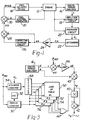
- FIGURE 1 there is shown a block diagram of a fuel control system for an internal combustion engine having a fuel control computer 10 generating fuel delivery signals Q indicative of the engine's fuel requirements in response to the operational parameters of an internal combustion engine 12.
- a fuel delivery device 14 receiving fuel from an external source (not shown) delivers the required quantity of fuel to the engine 12 in response to the fuel delivery signals Q.
- the fuel delivery device 14 may be of any type known in the art, such as a separate fuel injector for each engine cylinder, a single fuel injector (unit injector) for all of the engine's cylinders, or an electronically controlled carburetor.
- a means such as Digital Period Analyzer 16 generates an amplitude signal A indicative of the magnitude of each torque impulse produced by the individual engine cylinders in response to the instantaneous rotational velocity of the engine's crankshaft.
- An Amplitude Correction Circuit 18 responsive to the engine speed and rotational position of the engine's crankshaft and corrects on a cylinder by cylinder basis the amplitude signal A received from the Digital Period Analyzer 16. The corrected amplitude signals are then averaged for each cylinder in Averaging Circuit 20 to produce an individual average amplitude signal A for the torque impulses produced by each cylinder.
- An Integrator 22 integrates the average amplitude signals A generated by the Averaging Circuit 20 and outputs a difference signal A a indicative of the difference between the integrated average value Aavg.
- the difference signal ⁇ a is then amplified in Amplifier 24 to generate an amplified difference signal ⁇ A.
- the amplified difference signal ⁇ A is averaged in Correction Averaging Circuit 26.
- a Subtraction Circuit 28 subtracts the output of the Correction Averaging Circuit 26 from the amplified difference signal ⁇ A output from Amplifier 24 to generate a correction signal ⁇ Q.
- the correction signal ⁇ Q is then summed in Addition Circuit 30 with the fuel delivery signal Q generated by Fuel Control Computer 10 to generate a corrected fuel delivery signal Q + A Q correcting the quantity of fuel delivered to each cylinder.
- the corrected fuel delivery signal Q + A Q is operative to equalize the amplitudes of the torque impulses produced by all of the cylinders.
- the Digital Period Analyzer 16 such as disclosed in patent application Serial Number 187,400 generates a phase angle signal 0 and an amplitude signal A for each torque impulse in response to the instantaneous rotational velocity of the engine's crankshaft or other suitable rotational member of the engine.
- the Digital Period Analyzer first generates the functions A sin 0 and A cos ⁇ where A is the amplitude of the torque impulses and ⁇ is the phase angle of the torque impulses.
- the Digital Period Analyzer 16 then computes the value of the phase angle ⁇ and amplitude A in accordance with the equations
- the phase angle ⁇ is corrected for changing engine speed engine speed as disclosed in U.S. patent application (Docket No. 587-80-0139) entitled "Phase Angle Detector" (filed July 19, 1982.)
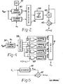
- the details of the Amplitude Correction Circuit 18 are shown on FIGURE 2.
- the amplitude of the torque impulse imparted to the engine's crankshaft are distorted by the rotational velocity of the engine's crankshaft, the positions of the individual cylinders along the crankshaft and other torsional vibrations that may occur. Since these distortions differ as a function of engine speed as well as from cylinder to cylinder the Amplitude Correction Circuit 18 may be embodied in the form of a look-up table storing a set of correction factors for each cylinder as a function of engine speed.
- the engine speed may be subdivided into a plurality of discrete speed ranges and the look up table storing a single correction factor for each cylinder for each speed range.
- the correction factors may be emperically determined from tests or computed from known engine dynamics.
- a Period Counter 30 is periodically reset by a reference signal 9 REF indicative of the engine's crankshaft rotating through a predetermined angle, such as when the piston in each cylinder assumes a predetermined position. This position may be the Top Dead Center (TDC) or any other selected position.
- TDC Top Dead Center
- Counter 30 is a variable speed counter as described in patent application Serial No. 187,400 which counts at a lower rate when the engine speed is below a predetermined value.
- a Cylinder Counter 34 is reset by a reference signal ⁇ o indicative of the beginning of each engine cycle.
- the Cylinder Counter 34 counts the reference signals 9 REF and generates a sequential set of numbers one for each engine cylinder. Each number generated in Cylinder Counter 34 uniquely identifies one of the engine's cylinders.
- the numbers stored in Period Counter 30 and Cylinder Counter 34 are input to Multiplexer 36 which generates an address identifying a specific storage location in a Look-Up-Table 38.
- the Look-Up-Table 38 may be a conventional read-only-memory (ROM) or any comparable type memory storing a set of correction factors "c i " for each engine cylinder as a function of engine speed.
- the address generated by the Multiplexer 36 identifies the cylinder in response to number received from the Cylinder Counter 34 and identifies the specific speed related correction factor for the cylinder in response to the number received from the Period Counter 30.
- the correction factor "c i " output from the Look-Up Table 38 is multiplied with the amplitude A generated by the Digital Period Analyzer 16 in a multiplier circuit 40 to produce a correction increment having a value equal to c i A.
- the amplitude correction is then summed with the amplitude signal A in a sum amplifier 42 to generate a corrected amplitude signal A + c i A corrected for both engine speed and other errors that may have been caused by the particular location of that particular cylinder along the engine's crankshaft.
- the correction factor stored in the Look-Up Table 38 may be (1 + c i ) eliminating the need for sum amplifier 42 as would be obvious to one skilled in the art.
- phase angle signal g is used to correct the amplitude signal A prior to the correction for engine speed and position of the cylinder along the engines crankshaft.
- maximum engine efficiency is obtained when the cylinder pressure occurs at a predetermined angle of the crankshaft past the top dead center (TDC) position.
- TDC top dead center
- C. K. Leung and R. W. Seitz in patent application Serial No. 187,400 filed on September 15, 1980 have disclosed that the phase angle of the torque impulse is a measure of the angle at which maximum cylinder pressure occurs.
- the amplitude of the torque impulse is less than it would have been had the phase angle been correct. Based on the assumption that the ignition or injection timing is being corrected independently to produce the desired phase angle, the amplitude should be first corrected for the phase angle error.
- phase angle g of the torque impulse generated by the Digital Period Analyzer 16 is first compared with a desired or reference phase angle ⁇ REF in a difference Amplifier 44 to generate a phase angle error signal A 0.
- the phase angle error signal is then amplified in Amplifier 46 to generate an amplitude correction signal ⁇ .
- the amplitude correction signal ⁇ is summed in Sum Amplifier 46 with the amplitude signal A output from the Digital Period Analyzer 16 to generate a phase angle correct amplitude signal A ⁇ .
- the alternate embodiment comprises a plurality of Look-Up Tables 50 through 56, each Look-Up Table storing a correction factor c i or (1 + c i ) for engine speed and the position of the cylinder along the engines crankshaft for a particular engine cylinder.
- the illustrated embodiment is for a 4 cylinder engine therefore there are 4 separate Look-Up-Tables. For a 6 cylinder engine, there would be 6 Look-Up-Tables etc.
- a Cylinder Counter 34 generates a number indicative of the cylinder which is producing the torque impulse being analyzed in response to the signals ⁇ o indicative of the beginning of each engine cycle and ⁇ REF indicative of the beginning of the torque impulse produced by each successive cylinder.
- the number stored in Cylinder Counter 34 indicative of the cylinder which produced the torque impulse is input to.
- a Decoder 58 which produces a signal on one of 4 output lines corresponding to the number received from the Cylinder Counter 34.
- Each of the four output lines of Decoder 58 are connected to the enable input of one of the four Look-Up-Tables 50 through 56.
- Period Counter 30 Simultaneously the Period Counter 30 generates a number which is inversely proportional to the engine speed in response to the number of pulses generated by Oscillator 32 during sequentially received reference signals ⁇ REF as previously discussed.
- the output of Period Counter 30 is used to address all four of the look up tables simultaneously.
- the Look-Up-Table enabled by the output from Decoder 58 will output the appropriate correction factor to Multiplier Circuit 40 through OR gate 60.
- the phase angle corrected amplitude A ⁇ is multiplied by the received correction factor in Multiplier Circuit 40, and summed with the phase angle corrected signal Ag in Sum Amplifier 42 to generate the corrected amplitude signal having a value: where the phase angle corrected amplitude A 0 is equal to:
- phase angle correction circuit illustrated with reference to FIGURE 3 may also be incorporated in the Amplitude Correction Circuit of FIGURE 2.
- the details of the Averaging Circuit 20 are shown in FIGURE 4.
- the Decoder 58 outputs a signal on four separate lines, one at a time in response to the number stored in Cylinder Counter 34.
- the Cylinder Counter 34 and Decoder 58 may be the same decoder discussed relative to FIGURE 3 or may be separate elements.
- the output lines of the Decoder 58 are connected to one input of a set of AND gates 62 through 68 which are enabled in a sequential order in response to the output signals of Decoder 58.
- the corrected amplitude signal A (1 + c i ) generated by the Amplitude Correction Circuit 18 is received at the other inputs to AND gates 62 through 68.
- the outputs of the AND gates are individually connected to the input of an associated averaging circuit 70 through 78, one for each engine cylinder.
- the corrected amplitude signals are sequentially input into the associated averaging circuit and averaged with the prior corrected amplitude signals received from the same engine cylinder.
- the averaging circuits 70 through 76 average the corrected amplitude signals in accordance with the equation: where the subscript "i" designates the particular cylinder.
- the averaging circuits may be of any type known in the art including the averaging circuit discussed in detail in patent application Serial No. 187,400.
- Decoder 58 The outputs from Decoder 58 along with the outputs from the Averaging Circuits 70 through 76 are connected to a Switch 78 which outputs the averaged amplitude signal A from the appropriate averaging circuit in a corresponding sequential order in response to the output of Decoder 58.
- FIGURE 5 The details of the Integrator 22 are shown on FIGURE 5. Referring to FIGURE 5, the average amplitude signals A i generated in averaging circuits 70 through 78 of FIGURE 4 are sequentially received by an integrator 80 which generates an integrated average signal A avg . having the value:
- the average signal A i is then compared with the integrated average signal in difference amplifier 82 to generate the amplitude error signal ⁇ , A.
- the integrator circuit may be an averaging circuit similar to averaging circuits 70 through 76 or any other circuit known in the art capable of producing an integrated average amplitude signal.
Landscapes
- Engineering & Computer Science (AREA)
- Chemical & Material Sciences (AREA)
- Combustion & Propulsion (AREA)
- Mechanical Engineering (AREA)
- General Engineering & Computer Science (AREA)
- Electrical Control Of Air Or Fuel Supplied To Internal-Combustion Engine (AREA)
- Combined Controls Of Internal Combustion Engines (AREA)
- Output Control And Ontrol Of Special Type Engine (AREA)
- Fuel-Injection Apparatus (AREA)
Priority Applications (1)
| Application Number | Priority Date | Filing Date | Title |
|---|---|---|---|
| AT83401707T ATE38080T1 (de) | 1982-09-01 | 1983-08-25 | System zur steuerung der kraftstoffverteilung fuer eine brennkraftmaschine. |
Applications Claiming Priority (2)
| Application Number | Priority Date | Filing Date | Title |
|---|---|---|---|
| US06/413,919 US4475511A (en) | 1982-09-01 | 1982-09-01 | Fuel distribution control system for an internal combustion engine |
| US413919 | 1999-10-07 |
Publications (3)
| Publication Number | Publication Date |
|---|---|
| EP0107523A2 true EP0107523A2 (de) | 1984-05-02 |
| EP0107523A3 EP0107523A3 (en) | 1985-09-11 |
| EP0107523B1 EP0107523B1 (de) | 1988-10-19 |
Family
ID=23639196
Family Applications (1)
| Application Number | Title | Priority Date | Filing Date |
|---|---|---|---|
| EP83401707A Expired EP0107523B1 (de) | 1982-09-01 | 1983-08-25 | System zur Steuerung der Kraftstoffverteilung für eine Brennkraftmaschine |
Country Status (6)
| Country | Link |
|---|---|
| US (1) | US4475511A (de) |
| EP (1) | EP0107523B1 (de) |
| JP (1) | JPS59136524A (de) |
| AT (1) | ATE38080T1 (de) |
| CA (1) | CA1205887A (de) |
| DE (1) | DE3378274D1 (de) |
Cited By (10)
| Publication number | Priority date | Publication date | Assignee | Title |
|---|---|---|---|---|
| EP0113510A3 (en) * | 1982-12-09 | 1985-09-18 | General Motors Corporation | Diesel fuel injection pump with adaptive torque balance control |
| EP0120730A3 (en) * | 1983-02-22 | 1985-10-23 | The Bendix Corporation | Fuel redistribution control for an internal combustion engine |
| DE3533900A1 (de) * | 1984-09-22 | 1986-04-03 | Diesel Kiki Co. Ltd., Tokio/Tokyo | Einrichtung zum steuern des lehrlaufbetriebes eines verbrennungsmotors |
| WO1987005074A1 (fr) * | 1986-02-17 | 1987-08-27 | Robert Bosch Gmbh | Dispositif pour le reglage de la stabilite de marche de moteurs a combustion |
| EP0235418A1 (de) * | 1986-03-03 | 1987-09-09 | Optimizer Control Corporation | System und Verfahren zum Optimieren der Arbeitsweise einer Kraftmaschine |
| EP0222486A3 (en) * | 1985-10-28 | 1987-10-07 | General Motors Corporation | Combustion control for an internal combustion engine |
| DE3700942C1 (de) * | 1987-01-15 | 1988-08-11 | Daimler Benz Ag | Verfahren zur Regelung der Gemischzusammensetzung bei einer gemischverdichtenden Brennkraftmaschine |
| EP0406765A1 (de) * | 1989-07-07 | 1991-01-09 | Siemens Aktiengesellschaft | Verfahren und Vorrichtung zur Drehzahlregelung eines langsamlaufenden, mehrzylindrischen Dieselmotors |
| EP0447697A3 (en) * | 1990-03-23 | 1992-03-04 | Mitsubishi Jukogyo Kabushiki Kaisha | Apparatus for suppressing torsional vibration of a crank shaft of a diesel engine |
| US5359518A (en) * | 1989-08-23 | 1994-10-25 | Audi Ag | Process for monitoring the power output of the individual cylinders of a multicylinder internal combustion engine |
Families Citing this family (16)
| Publication number | Priority date | Publication date | Assignee | Title |
|---|---|---|---|---|
| DE3336028C3 (de) * | 1983-10-04 | 1997-04-03 | Bosch Gmbh Robert | Einrichtung zur Beeinflussung von Steuergrößen einer Brennkraftmaschine |
| JPH0650077B2 (ja) * | 1984-08-10 | 1994-06-29 | 日本電装株式会社 | 内燃機関用燃料噴射量制御方法 |
| US4883038A (en) * | 1986-10-31 | 1989-11-28 | Japan Electronic Control Systems Co., Ltd. | Fuel supply control system for multi-cylinder internal combustion engine with feature of suppression of output fluctuation between individual engine cylinders |
| JP2510250B2 (ja) * | 1988-08-30 | 1996-06-26 | 日産自動車株式会社 | 内燃機関の燃焼制御装置 |
| US4936277A (en) * | 1988-12-19 | 1990-06-26 | Motorola, Inc. | System for monitoring and/or controlling multiple cylinder engine performance |
| US5069185A (en) * | 1990-06-15 | 1991-12-03 | Edward J. Evasick | Diesel tune-up method |
| JPH04214946A (ja) * | 1990-12-14 | 1992-08-05 | Toyota Motor Corp | 内燃機関のトルク変動制御装置 |
| DE4122139C2 (de) * | 1991-07-04 | 2000-07-06 | Bosch Gmbh Robert | Verfahren zur Zylindergleichstellung bezüglich der Kraftstoff-Einspritzmengen bei einer Brennkraftmaschine |
| JP3426295B2 (ja) * | 1992-09-25 | 2003-07-14 | ローベルト ボツシユ ゲゼルシヤフト ミツト ベシユレンクテル ハフツング | 電子装置を検査する方法および装置 |
| EP0763725A3 (de) * | 1995-09-14 | 1999-07-21 | MTU Motoren- und Turbinen-Union Friedrichshafen GmbH | Verfahren zur Bestimmung der Unterschiede ungleichförmiger Zylindermomente bei einer Brennkraftmaschine und Anwendung des Verfahrens |
| DE19845749A1 (de) * | 1998-10-05 | 2000-04-06 | Bayerische Motoren Werke Ag | Verfahren zur Kompensation des Einflusses unterschiedlicher Leckluftmengen |
| US6209520B1 (en) * | 1999-06-15 | 2001-04-03 | Ilya V. Kolmanovsky | Method and apparatus for cylinder balancing |
| DE10009065A1 (de) * | 2000-02-25 | 2001-09-13 | Bosch Gmbh Robert | Verfahren und Einrichtung zur Steuerung einer mehrzylindrigen Brennkraftmaschine |
| JP2008175457A (ja) * | 2007-01-18 | 2008-07-31 | Sanyo Electric Co Ltd | 床置き式空気調和機 |
| DE102008002424A1 (de) * | 2007-12-19 | 2009-06-25 | Robert Bosch Gmbh | Verfahren zum Betreiben einer Brennkraftmaschine |
| JP6403939B2 (ja) * | 2012-02-29 | 2018-10-10 | ジョンソン・アンド・ジョンソン・ビジョン・ケア・インコーポレイテッドJohnson & Johnson Vision Care, Inc. | 電圧が印加される収容アレイを有する涙点プラグ |
Family Cites Families (7)
| Publication number | Priority date | Publication date | Assignee | Title |
|---|---|---|---|---|
| DE2457461A1 (de) * | 1974-12-05 | 1976-06-10 | Bosch Gmbh Robert | Vorrichtung zur bestimmung der kraftstoffeinspritzmenge bei gemischverdichtenden brennkraftmaschinen |
| US4197767A (en) * | 1978-05-08 | 1980-04-15 | The Bendix Corporation | Warm up control for closed loop engine roughness fuel control |
| US4375668A (en) * | 1978-05-08 | 1983-03-01 | The Bendix Corporation | Timing optimization control |
| US4357662A (en) * | 1978-05-08 | 1982-11-02 | The Bendix Corporation | Closed loop timing and fuel distribution controls |
| DE2941977A1 (de) * | 1979-10-17 | 1981-04-30 | Robert Bosch Gmbh, 7000 Stuttgart | Einrichtung zum optimieren von betriebskenngroessen einer brennkraftmaschine |
| JPS58176424A (ja) * | 1982-04-09 | 1983-10-15 | Nippon Denso Co Ltd | エンジンシリンダ別燃料調量バラツキ補正方法 |
| US4418669A (en) * | 1982-07-19 | 1983-12-06 | The Bendix Corporation | Fuel distribution control system for an internal combustion engine |
-
1982
- 1982-09-01 US US06/413,919 patent/US4475511A/en not_active Expired - Lifetime
-
1983
- 1983-08-24 CA CA000435257A patent/CA1205887A/en not_active Expired
- 1983-08-25 EP EP83401707A patent/EP0107523B1/de not_active Expired
- 1983-08-25 DE DE8383401707T patent/DE3378274D1/de not_active Expired
- 1983-08-25 AT AT83401707T patent/ATE38080T1/de active
- 1983-09-01 JP JP58161166A patent/JPS59136524A/ja active Granted
Cited By (11)
| Publication number | Priority date | Publication date | Assignee | Title |
|---|---|---|---|---|
| EP0113510A3 (en) * | 1982-12-09 | 1985-09-18 | General Motors Corporation | Diesel fuel injection pump with adaptive torque balance control |
| EP0120730A3 (en) * | 1983-02-22 | 1985-10-23 | The Bendix Corporation | Fuel redistribution control for an internal combustion engine |
| DE3533900A1 (de) * | 1984-09-22 | 1986-04-03 | Diesel Kiki Co. Ltd., Tokio/Tokyo | Einrichtung zum steuern des lehrlaufbetriebes eines verbrennungsmotors |
| EP0222486A3 (en) * | 1985-10-28 | 1987-10-07 | General Motors Corporation | Combustion control for an internal combustion engine |
| WO1987005074A1 (fr) * | 1986-02-17 | 1987-08-27 | Robert Bosch Gmbh | Dispositif pour le reglage de la stabilite de marche de moteurs a combustion |
| EP0235418A1 (de) * | 1986-03-03 | 1987-09-09 | Optimizer Control Corporation | System und Verfahren zum Optimieren der Arbeitsweise einer Kraftmaschine |
| DE3700942C1 (de) * | 1987-01-15 | 1988-08-11 | Daimler Benz Ag | Verfahren zur Regelung der Gemischzusammensetzung bei einer gemischverdichtenden Brennkraftmaschine |
| EP0406765A1 (de) * | 1989-07-07 | 1991-01-09 | Siemens Aktiengesellschaft | Verfahren und Vorrichtung zur Drehzahlregelung eines langsamlaufenden, mehrzylindrischen Dieselmotors |
| WO1991000956A1 (de) * | 1989-07-07 | 1991-01-24 | Siemens Aktiengesellschaft | Verfahren und vorrichtung zur drehzahlregelung eines langsamlaufenden, mehrzylindrischen dieselmotors |
| US5359518A (en) * | 1989-08-23 | 1994-10-25 | Audi Ag | Process for monitoring the power output of the individual cylinders of a multicylinder internal combustion engine |
| EP0447697A3 (en) * | 1990-03-23 | 1992-03-04 | Mitsubishi Jukogyo Kabushiki Kaisha | Apparatus for suppressing torsional vibration of a crank shaft of a diesel engine |
Also Published As
| Publication number | Publication date |
|---|---|
| DE3378274D1 (en) | 1988-11-24 |
| US4475511A (en) | 1984-10-09 |
| EP0107523A3 (en) | 1985-09-11 |
| EP0107523B1 (de) | 1988-10-19 |
| JPS59136524A (ja) | 1984-08-06 |
| CA1205887A (en) | 1986-06-10 |
| JPH059624B2 (de) | 1993-02-05 |
| ATE38080T1 (de) | 1988-11-15 |
Similar Documents
| Publication | Publication Date | Title |
|---|---|---|
| EP0107523B1 (de) | System zur Steuerung der Kraftstoffverteilung für eine Brennkraftmaschine | |
| US4418669A (en) | Fuel distribution control system for an internal combustion engine | |
| US4535406A (en) | Fuel distribution control for an internal combustion engine | |
| US6546912B2 (en) | On-line individual fuel injector diagnostics from instantaneous engine speed measurements | |
| US4357662A (en) | Closed loop timing and fuel distribution controls | |
| US4936277A (en) | System for monitoring and/or controlling multiple cylinder engine performance | |
| US6021758A (en) | Method and apparatus for engine cylinder balancing using sensed engine speed | |
| US4688535A (en) | Apparatus for influencing control quantities of an internal combustion engine | |
| US4197767A (en) | Warm up control for closed loop engine roughness fuel control | |
| US4744243A (en) | Method of and apparatus for detecting maximum cylinder pressure angle in internal combustion engine | |
| JP3348107B2 (ja) | 内燃機関の燃料噴射量調整方法 | |
| EP0735261A2 (de) | Motorsteuerung mit Kompensation der Luftdurchflussmesseinrichtung | |
| US4375668A (en) | Timing optimization control | |
| EP0024733B1 (de) | Verfahren und System zum Betrieb einer Brennkraftmaschine bei maximalem Drehmoment unter veränderlichen Arbeitsumständen | |
| GB2024462A (en) | Integrated Closed Loop Engine Control System | |
| US4337647A (en) | Engine roughness sensor | |
| US4478185A (en) | Air-fuel ratio and ignition timing regulation by detecting engine running condition | |
| EP0812981B1 (de) | Verfahren und Vorrichtung zur Steuerung der Einspritzung im Übergangszustand für einen aufgeladenen Dieselmotor | |
| US4932376A (en) | Control system for the transient operation of an internal combustion engine | |
| JPH10227251A (ja) | 内燃機関の制御方法および装置 | |
| US4476833A (en) | Phase angle modification of the torque amplitude for fuel distribution control systems | |
| US6302083B1 (en) | Method for cylinder equalization in an internal combustion engine operating by direct injection | |
| US4520449A (en) | Phase angle detector | |
| US4643153A (en) | Electronic arrangement for generating a fuel metering signal for an internal combustion engine | |
| JPS60249645A (ja) | 内燃エンジンの燃料供給制御方法 |
Legal Events
| Date | Code | Title | Description |
|---|---|---|---|
| PUAI | Public reference made under article 153(3) epc to a published international application that has entered the european phase |
Free format text: ORIGINAL CODE: 0009012 |
|
| AK | Designated contracting states |
Designated state(s): AT DE FR GB IT SE |
|
| PUAL | Search report despatched |
Free format text: ORIGINAL CODE: 0009013 |
|
| RHK1 | Main classification (correction) |
Ipc: F02D 41/14 |
|
| AK | Designated contracting states |
Designated state(s): AT DE FR GB IT SE |
|
| 17P | Request for examination filed |
Effective date: 19860130 |
|
| 17Q | First examination report despatched |
Effective date: 19870224 |
|
| D17Q | First examination report despatched (deleted) | ||
| RAP1 | Party data changed (applicant data changed or rights of an application transferred) |
Owner name: ALLIED CORPORATION |
|
| RAP1 | Party data changed (applicant data changed or rights of an application transferred) |
Owner name: ALLIED-SIGNAL INC. |
|
| GRAA | (expected) grant |
Free format text: ORIGINAL CODE: 0009210 |
|
| AK | Designated contracting states |
Kind code of ref document: B1 Designated state(s): AT DE FR GB IT SE |
|
| REF | Corresponds to: |
Ref document number: 38080 Country of ref document: AT Date of ref document: 19881115 Kind code of ref document: T |
|
| REF | Corresponds to: |
Ref document number: 3378274 Country of ref document: DE Date of ref document: 19881124 |
|
| ET | Fr: translation filed | ||
| ITF | It: translation for a ep patent filed | ||
| PLBE | No opposition filed within time limit |
Free format text: ORIGINAL CODE: 0009261 |
|
| STAA | Information on the status of an ep patent application or granted ep patent |
Free format text: STATUS: NO OPPOSITION FILED WITHIN TIME LIMIT |
|
| 26N | No opposition filed | ||
| ITTA | It: last paid annual fee | ||
| EAL | Se: european patent in force in sweden |
Ref document number: 83401707.1 |
|
| PGFP | Annual fee paid to national office [announced via postgrant information from national office to epo] |
Ref country code: GB Payment date: 20000703 Year of fee payment: 18 Ref country code: AT Payment date: 20000703 Year of fee payment: 18 |
|
| PGFP | Annual fee paid to national office [announced via postgrant information from national office to epo] |
Ref country code: SE Payment date: 20000802 Year of fee payment: 18 |
|
| PGFP | Annual fee paid to national office [announced via postgrant information from national office to epo] |
Ref country code: FR Payment date: 20000803 Year of fee payment: 18 |
|
| PGFP | Annual fee paid to national office [announced via postgrant information from national office to epo] |
Ref country code: DE Payment date: 20000830 Year of fee payment: 18 |
|
| PG25 | Lapsed in a contracting state [announced via postgrant information from national office to epo] |
Ref country code: GB Free format text: LAPSE BECAUSE OF NON-PAYMENT OF DUE FEES Effective date: 20010825 Ref country code: AT Free format text: LAPSE BECAUSE OF NON-PAYMENT OF DUE FEES Effective date: 20010825 |
|
| PG25 | Lapsed in a contracting state [announced via postgrant information from national office to epo] |
Ref country code: SE Free format text: LAPSE BECAUSE OF NON-PAYMENT OF DUE FEES Effective date: 20010826 |
|
| EUG | Se: european patent has lapsed |
Ref document number: 83401707.1 |
|
| GBPC | Gb: european patent ceased through non-payment of renewal fee |
Effective date: 20010825 |
|
| PG25 | Lapsed in a contracting state [announced via postgrant information from national office to epo] |
Ref country code: FR Free format text: LAPSE BECAUSE OF NON-PAYMENT OF DUE FEES Effective date: 20020430 |
|
| PG25 | Lapsed in a contracting state [announced via postgrant information from national office to epo] |
Ref country code: DE Free format text: LAPSE BECAUSE OF NON-PAYMENT OF DUE FEES Effective date: 20020501 |
|
| REG | Reference to a national code |
Ref country code: FR Ref legal event code: ST |