EP0107341A2 - Vorrichtung zur Analyse eines brennbaren Gases - Google Patents
Vorrichtung zur Analyse eines brennbaren Gases Download PDFInfo
- Publication number
- EP0107341A2 EP0107341A2 EP83305552A EP83305552A EP0107341A2 EP 0107341 A2 EP0107341 A2 EP 0107341A2 EP 83305552 A EP83305552 A EP 83305552A EP 83305552 A EP83305552 A EP 83305552A EP 0107341 A2 EP0107341 A2 EP 0107341A2
- Authority
- EP
- European Patent Office
- Prior art keywords
- air
- combustion
- gas
- fuel
- rotor
- Prior art date
- Legal status (The legal status is an assumption and is not a legal conclusion. Google has not performed a legal analysis and makes no representation as to the accuracy of the status listed.)
- Withdrawn
Links
- 239000002737 fuel gas Substances 0.000 title claims abstract description 26
- 238000002485 combustion reaction Methods 0.000 claims abstract description 40
- 239000000203 mixture Substances 0.000 claims abstract description 11
- 239000007789 gas Substances 0.000 claims description 36
- 239000000446 fuel Substances 0.000 claims description 21
- QVGXLLKOCUKJST-UHFFFAOYSA-N atomic oxygen Chemical compound [O] QVGXLLKOCUKJST-UHFFFAOYSA-N 0.000 claims description 14
- 239000001301 oxygen Substances 0.000 claims description 14
- 229910052760 oxygen Inorganic materials 0.000 claims description 14
- 238000004458 analytical method Methods 0.000 claims description 4
- 238000004868 gas analysis Methods 0.000 claims 1
- 238000005259 measurement Methods 0.000 description 10
- 238000010926 purge Methods 0.000 description 3
- IYRWEQXVUNLMAY-UHFFFAOYSA-N carbonyl fluoride Chemical compound FC(F)=O IYRWEQXVUNLMAY-UHFFFAOYSA-N 0.000 description 2
- 238000009434 installation Methods 0.000 description 2
- 238000012423 maintenance Methods 0.000 description 2
- 239000011248 coating agent Substances 0.000 description 1
- 238000000576 coating method Methods 0.000 description 1
- 239000000470 constituent Substances 0.000 description 1
- 238000010276 construction Methods 0.000 description 1
- 230000001276 controlling effect Effects 0.000 description 1
- 238000010586 diagram Methods 0.000 description 1
- 238000005553 drilling Methods 0.000 description 1
- 230000000694 effects Effects 0.000 description 1
- 239000012530 fluid Substances 0.000 description 1
- 239000002783 friction material Substances 0.000 description 1
- 238000010438 heat treatment Methods 0.000 description 1
- 238000004519 manufacturing process Methods 0.000 description 1
- 230000003287 optical effect Effects 0.000 description 1
- -1 polytetrafluorethylene Polymers 0.000 description 1
- 229920001343 polytetrafluoroethylene Polymers 0.000 description 1
- 230000001105 regulatory effect Effects 0.000 description 1
- 238000005070 sampling Methods 0.000 description 1
Images
Classifications
-
- G—PHYSICS
- G01—MEASURING; TESTING
- G01N—INVESTIGATING OR ANALYSING MATERIALS BY DETERMINING THEIR CHEMICAL OR PHYSICAL PROPERTIES
- G01N33/00—Investigating or analysing materials by specific methods not covered by groups G01N1/00 - G01N31/00
- G01N33/22—Fuels; Explosives
- G01N33/225—Gaseous fuels, e.g. natural gas
Definitions
- the present invention relates to fuel gas analyzing apparatus and more specifically to analyzers for determining the calorific content of a combustible gas.
- calorific content e.g., BTU content
- a combustible gas such as that supplied for home heating by a public utility, etc.
- Known gas analyzers of this latter type include ones based on the use of the thermal conductivity of the known gas which gas is analyzed by comparing its rate of thermal conductivity with that of a standard reference gas.
- Another prior art gas analyzing device uses a catalyzing wire which has its temperature affected by a gas being burned adjacent to the wire to produce an output signal which is .used to ascertain the percentage of combustible gas in the gas being tested.
- An additional group of gas analyzers are based on an optical analysis of the colour, etc., of a gas flame to provide a measure of combustible gas content.
- an improved fuel gas analysing apparatus comprising means producing a mixture of fuel gas and air in any one of a plurality of different ratios, combustion means producing a combustion of the mixture, and a sensor sensing the combustion products to provide an output signal representative of the state of combustion, characterised by a controller operable in response to an output of the sensor to control the mixture producing means to obtain a first substantially stoichiometric combustion, and to obtain a second substantially stoichiometric combustion, upon the introduction of additional air, and to provide an analysis of the gas determined from the control of said first and second combustions.
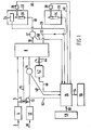
- a calorific content measuring system includes a fuel gas inlet pipeline 2.supplying fuel gas to a pressure regulator 4.
- the output of the pressure regulator 4 is applied to a solenoid controlled flow selection valve 6 and to one input of a rotary mixing valve 8.
- An air inlet pipeline 10 is arranged to supply combustion air to a second pressure regulator 12, the output of which is applied to the selection valve 6 and via a temperature sensor 14 to another input of the valve 8.
- the output of the selection valve 6 is supplied through pipeline 15 to a further input of the valve 8.
- One output from the rotary mixing valve 8 is supplied through pipeline 16 to a temperature sensor 17, the output of which is supplied through pipeline 18 to a burner 20 located in a primary or measuring combustion chamber 22.
- An electrochemical combustion product sensor 24 is located in the combustion chamber 22 for sensing the combustion products from the burner 20.
- An output signal from the sensor 24 is connected to a first input of a system control apparatus 26.
- the system control 26 may be . any suitable device for producing an output in response to a predetermined relationship of input signals applied thereto, e.g., a microprocessor operating under control of a fixed stored program, such devices being well-known in the art.
- a first ignition and flame safeguard device 28 is also located in the combustion chamber 22 and is controlled over signal line 30 by the system control 26 to effect ignition of the burner 20 and to sense the presence of a burner flame.
- a second output from the valve 8 is connected through pipeline 32 to a second burner 34 located in a second or flare combustion chamber 36, which burns off any excess gas.
- a second ignition and flame safeguard device 38 is located in the chamber 34 and is controlled by the system control 26 over line 40.
- a motor 42 drives the valve 8 by a motor shaft 44 connected therebetween.
- the motor 42 is energized by the system control 26 over line 46 connected to a first output of system control 26 and may be any suitable drive device capable of being precisely controlled for rotational speed, e.g., a stepping motor.
- the temperature sensor 14 is connected by line 48 to a second input of the system control 26 while the second temperature sensor 17 is connected by a line 50 to a third input of the system control 26.
- a second output from the system control 26 to the selection valve 6 is applied by a line 52.
- a third output from the system control 26 is connected by a line 54 to a display 56 for displaying the calorific content of the combustible fuel gas being tested, e.g., BTU content.
- a keyboard 58 connected to the system control 26 by a line 60 is provided to supply control signals to the system control 26 which as previously mentioned may include a microprocessor having a memory for storing control signals as digital words therein.
- valve 8 In the embodiment of the invention shown in Figure 1, fuel and air from pressure regulators 4, 12, respectively, are fed through the valve 8 in which the proportion of air to fuel gas transferred therethrough to the primary or measurement combustion chamber 22 depends on the speed of rotation of the valve 8.
- the valve 8 contains hollow chambers or transfer buckets in a rotor driven by the motor 42 which are alternately filled with fuel and purged with air as they are rotated past a fixed plate having first slots therein supplied with the fuel gas and air for filling the buckets, and second slots for receiving the fuel gas and air from the buckets and which are connected to the primary and secondary combustion chambers 22, 36, respectively, as described more fully hereinafter with respect to Figures 2 and 3.
- the fixed volume slots and buckets are arranged to interact in a manner whereby the air flow remains constant, and the fuel gas introduced varies with the angular speed of the rotor whereby the air-fuel ratio of the mixture supplied to the measurement combustion chamber 22 is controlled by the rotational speed of the rotor.
- the motor 42 driving the rotor is speed controlled by the system control 26 to allow for flexibility in adjusting the rotational speed of the rotor and, thus, the air-fuel ratio to achieve substantially stoichiometric combustion.
- the oxygen sensor 24 detects the excess oxygen in the combustion products from the burner 20 and produces a step change in its output signal at substantially stoichiometric combustion.
- the output signal from the sensor 24 representative of the detected oxygen level is applied via line 25 to the system control 26.
- the system control 26 is arranged to respond to the output signal from the sensor 24 to produce a first controller output signal on line 46 for controlling the speed of the motor 42, and , consequently, the rotor within the valve 8.
- the system control 26 is also arranged to provide a second output signal on line 54 representative of the speed of the motor 42 for application to a display device 56 for providing display of the calorific content of the fuel gas, e.g., the display device 56 may be a digital display for displaying the calorific content in BTU's.
- the calculation of the heat content of the combustible gas is made by utilizing a microprocessor system operating in accordance with a fixed stored program to solve a predetermined equation from a simplified known constant relationship between the air-fuel ratio at substantially the stoichiometric point which is known from the speed of the sampling or mixing system and the corresponding fuel heat content.
- the results are subsequently recorded or displayed in a suitable manner.
- the system described in our U.S. Patent No.4386 858 has a disadvantage in that the combustible fuel gas often contains entrained oxygen which provides oxygen for combustion with the combustible gas constituents at the burner in addition to the oxygen provided by the air supply.
- This error can be corrected by making two measurements of the unknown combustible gas.
- the first measurement is taken in the normal way as described above using the calorific content analyzer, and the speed of the rotary valve providing the variable air-fuel ratio for substantially stoichiometric combustion is controlled and stored in the system control 26.
- the second measurement is made when substantially stoichiometric combustion is attained with a known amount of air added to the unknown combustible gas stream.
- This equation is derived from an analyzer system model analysis with oxygen in fuel and without oxygen in fuel with a final subtraction of the two descriptive equations.
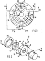
- the rotary valve 8 includes a rotor 62 connected to motor 42 via shaft 44.
- the rotor 62 has surface depressions forming chambers of fluid carrying transfer buckets located in its surface with first and second groups of radially extending chambers or buckets 64, 66, the first and second groups extending over different radial distances from the centre of the rotor 62.
- a fixed plate or stator 68 described more fully hereinafter is connected to the motor 42 and is used to provide the connections for the pipelines 5, 13, 15, 16 and 32.
- a cover' 70 is arranged to cover the rotor 62 and is attached to the stator 68 by any suitable means such as screws 72.
- the package of the rotor, the stator 68 and the cover 70 is attached to the motor 42 by any suitable means such as screws 74.
- the surface of the stator 68, facing buckets 64, 66 has three groups of coaxial slots or grooves therein(See Figure 3) for supplying and receiving gases.
- some of the slots receive air or fuel gas supplied to the rotary valve 8 for application to the buckets 64, 66 while others supply air and gas via lines 16, 18 to the main burner 20 and via line 32 to the flare burner 34 after receiving the air and gas from the buckets 64, 66.
- Slots 76, 78 are arranged outermost from the centre of the stator 68, slots 80 and 82 are at an intermediate radius, while slots 84, 86 are closest to the centre of the stator 68.
- Slots 78 and 86 encompass an arc of approximately 153°, the intermediate slot 80 covers approximately 208°, slots 76 and 84 cover approximately 49° while intermediate slot 82 covers approximately 70°.
- the air receiving slots 76 and 84 are shorter than either the fuel gas receiving slot 86 or the selective air-gas receiving slot 78.
- the main burner supply slot 82 is shorter than the flare or secondary burner supply slot 80.
- Internal drillings (not shown) in the stator'68 connect the slots.76, 78, 80, 82, 84 and 86 to respective ones of the pipelines 5, 13, 15, 16 and 32.
- the relationship of the slots 76, 78, 80, 82 and 84 in the face of the stator 68 and the groups of transfer buckets 64 and 66 in the rotor 62 are shown in Figure 3 by a phantom representation of the groups of buckets 64 and 66.
- the rotor 62 is urged against the stator 68 to provide a substantially fluid-tight seal between the contacting faces thereof having the buckets 64, 66 and the slots 76, 78, 80, 82, 84 and 86 therein.
- This seal may be enhanced by coating the contacting faces of the rotor 62 and the stator 68 with a low friction material, e.g., polytetrafluorethylene.
- the selection valve 6 is set to enable fuel gas purging of the outer buckets 66.
- the normal operation of the calorific content analyzer then results in the determination of f 1 based on the required rotary valve motor speed needed to achieve substantially stoichiometric combustion.
- the selection valve 6 is switched to enable additional air purging of the outer transfer buckets 66.
- fuel gas purging is maintained on the inner buckets 64.
- the concentration of air added to the fuel gas when the rotary valve dumps the transfer buckets 64 and 66 into the primary or measurement burner 20 is proportional to the ratio of .
- the concentration of the air added to the gas is fixed by the size of the transfer buckets 64, 66 and therefore is known by:
- the true calorific content value of the fuel gas can then be determined by solving the first equation shown above where f 2 is found by determining the rotary valve motor speed required for substantially stoichiometric combustion with the added air.
- the value of C OF2 would be determined by means of a calibration gas of known calorific content. This calibration gas would be measured during substantially stoichiometric combustion with and without the added air to indirectly determine C OF2 .
Landscapes
- Chemical & Material Sciences (AREA)
- Health & Medical Sciences (AREA)
- Engineering & Computer Science (AREA)
- Life Sciences & Earth Sciences (AREA)
- Medicinal Chemistry (AREA)
- Biochemistry (AREA)
- General Chemical & Material Sciences (AREA)
- Food Science & Technology (AREA)
- Chemical Kinetics & Catalysis (AREA)
- Physics & Mathematics (AREA)
- Analytical Chemistry (AREA)
- Oil, Petroleum & Natural Gas (AREA)
- General Health & Medical Sciences (AREA)
- General Physics & Mathematics (AREA)
- Immunology (AREA)
- Pathology (AREA)
- Investigating Or Analyzing Materials Using Thermal Means (AREA)
- Regulation And Control Of Combustion (AREA)
Applications Claiming Priority (2)
| Application Number | Priority Date | Filing Date | Title |
|---|---|---|---|
| US06/433,181 US4511262A (en) | 1982-10-06 | 1982-10-06 | Fuel entrained oxygen compensation for calorific content analyzer |
| US433181 | 1999-11-03 |
Publications (2)
| Publication Number | Publication Date |
|---|---|
| EP0107341A2 true EP0107341A2 (de) | 1984-05-02 |
| EP0107341A3 EP0107341A3 (de) | 1985-10-02 |
Family
ID=23719140
Family Applications (1)
| Application Number | Title | Priority Date | Filing Date |
|---|---|---|---|
| EP83305552A Withdrawn EP0107341A3 (de) | 1982-10-06 | 1983-09-21 | Vorrichtung zur Analyse eines brennbaren Gases |
Country Status (4)
| Country | Link |
|---|---|
| US (1) | US4511262A (de) |
| EP (1) | EP0107341A3 (de) |
| JP (1) | JPS5991348A (de) |
| CA (1) | CA1196799A (de) |
Cited By (8)
| Publication number | Priority date | Publication date | Assignee | Title |
|---|---|---|---|---|
| FR2564591A1 (fr) * | 1984-05-18 | 1985-11-22 | Siderurgie Fse Inst Rech | Comburimetre et methodes d'utilisation pour la determination du pouvoir comburivore et de l'indice de comburite des combustibles |
| EP0224655A1 (de) * | 1985-11-30 | 1987-06-10 | Dr.Ing.h.c. F. Porsche Aktiengesellschaft | Verfahren zum Bestimmen der stöchiometrischen Luftmengen von Kraftstoffen |
| FR2626673A1 (fr) * | 1988-01-29 | 1989-08-04 | Gaz De France | Procede et dispositif de mesurage de la puissance calorifique vehiculee par un courant de matiere combustible |
| EP0323658A3 (de) * | 1987-12-05 | 1990-06-13 | N.V. Nederlandse Gasunie | Verfahren zum Bestimmen der Wobbezahl eines Gasgemisches |
| EP0405693A1 (de) * | 1989-06-30 | 1991-01-02 | N.V. Nederlandse Gasunie | Verfahren und Vorrichtung zur Wobbezahl-Determination |
| EP0407818A1 (de) * | 1989-07-12 | 1991-01-16 | Horiba, Ltd. | Wasserstoffprüfgerät |
| ES2079308A2 (es) * | 1993-10-29 | 1996-01-01 | Univ Granada | Metodo de control electromecanico de valvulas rotatorias para la insercion o mezcla de fluidos. |
| CN111766330A (zh) * | 2020-06-30 | 2020-10-13 | 南京三鸣智自动化工程有限公司 | 一种气体的检测装置及检测方法 |
Families Citing this family (8)
| Publication number | Priority date | Publication date | Assignee | Title |
|---|---|---|---|---|
| US4761744A (en) * | 1986-11-24 | 1988-08-02 | The United States Of America As Represented By The Administrator Of The National Aeronautics And Space Administration | Method and device for determining heats of combustion of gaseous hydrocarbons |
| US4926356A (en) * | 1988-02-29 | 1990-05-15 | The Boeing Company | Test apparatus for measuring heat release of certain materials |
| US5224776A (en) * | 1989-02-24 | 1993-07-06 | Precision Measurement, Inc. | Instrument and method for heating value measurement by stoichiometric combustion |
| US5288149A (en) * | 1992-03-12 | 1994-02-22 | Panametrics, Inc. | Gas calorimeter and wobbe index meter |
| US5707150A (en) * | 1995-09-19 | 1998-01-13 | Rosemount Analytical Inc. | Apparatus for computing BTU content in a sample of gas |
| JP2008274883A (ja) * | 2007-05-01 | 2008-11-13 | Toyota Motor Corp | 内燃機関の制御装置 |
| US20140064325A1 (en) * | 2012-09-06 | 2014-03-06 | General Electric Company | Wheelspace flow visualization using pressure-sensitive paint |
| CN103808759A (zh) * | 2014-02-25 | 2014-05-21 | 中国计量学院 | 一种燃烧法燃气热值测量装置的配气系统 |
Family Cites Families (8)
| Publication number | Priority date | Publication date | Assignee | Title |
|---|---|---|---|---|
| US4386858A (en) * | 1979-12-20 | 1983-06-07 | Honeywell Inc. | Method and apparatus for determining the heat content of gaseous fuels |
| EP0031145B1 (de) * | 1979-12-20 | 1985-01-16 | Honeywell Inc. | Verfahren und Vorrichtung zur Bestimmung des volumetrischen Wärmeinhalts gasförmiger Brennstoffe |
| US4351614A (en) * | 1980-03-19 | 1982-09-28 | Eaton Corporation | Method of and apparatus for continually monitoring the heating value of a fuel gas using a combustibility meter |
| US4337654A (en) * | 1980-09-02 | 1982-07-06 | International Telephone And Telegraph Corporation | Natural gas calorimeter |
| DE3275237D1 (de) * | 1981-03-17 | 1987-02-26 | Honeywell Inc | A combustible gas analyzer |
| US4382698A (en) * | 1981-03-17 | 1983-05-10 | Honeywell Inc. | Combustible gas analyzer |
| US4396299A (en) * | 1981-06-10 | 1983-08-02 | Precision Machine Products, Inc. | Method and apparatus for determining total energy flow in a gas line |
| US4415278A (en) * | 1982-02-08 | 1983-11-15 | Honeywell Inc. | Method for operating a gas analyzing system and apparatus utilizing the same |
-
1982
- 1982-10-06 US US06/433,181 patent/US4511262A/en not_active Expired - Lifetime
-
1983
- 1983-07-28 CA CA000433452A patent/CA1196799A/en not_active Expired
- 1983-09-21 EP EP83305552A patent/EP0107341A3/de not_active Withdrawn
- 1983-10-06 JP JP58187660A patent/JPS5991348A/ja active Pending
Cited By (9)
| Publication number | Priority date | Publication date | Assignee | Title |
|---|---|---|---|---|
| FR2564591A1 (fr) * | 1984-05-18 | 1985-11-22 | Siderurgie Fse Inst Rech | Comburimetre et methodes d'utilisation pour la determination du pouvoir comburivore et de l'indice de comburite des combustibles |
| EP0224655A1 (de) * | 1985-11-30 | 1987-06-10 | Dr.Ing.h.c. F. Porsche Aktiengesellschaft | Verfahren zum Bestimmen der stöchiometrischen Luftmengen von Kraftstoffen |
| EP0323658A3 (de) * | 1987-12-05 | 1990-06-13 | N.V. Nederlandse Gasunie | Verfahren zum Bestimmen der Wobbezahl eines Gasgemisches |
| FR2626673A1 (fr) * | 1988-01-29 | 1989-08-04 | Gaz De France | Procede et dispositif de mesurage de la puissance calorifique vehiculee par un courant de matiere combustible |
| EP0405693A1 (de) * | 1989-06-30 | 1991-01-02 | N.V. Nederlandse Gasunie | Verfahren und Vorrichtung zur Wobbezahl-Determination |
| EP0407818A1 (de) * | 1989-07-12 | 1991-01-16 | Horiba, Ltd. | Wasserstoffprüfgerät |
| ES2079308A2 (es) * | 1993-10-29 | 1996-01-01 | Univ Granada | Metodo de control electromecanico de valvulas rotatorias para la insercion o mezcla de fluidos. |
| CN111766330A (zh) * | 2020-06-30 | 2020-10-13 | 南京三鸣智自动化工程有限公司 | 一种气体的检测装置及检测方法 |
| CN111766330B (zh) * | 2020-06-30 | 2022-04-19 | 南京三鸣智自动化工程有限公司 | 一种气体的检测装置及检测方法 |
Also Published As
| Publication number | Publication date |
|---|---|
| EP0107341A3 (de) | 1985-10-02 |
| US4511262A (en) | 1985-04-16 |
| CA1196799A (en) | 1985-11-19 |
| JPS5991348A (ja) | 1984-05-26 |
Similar Documents
| Publication | Publication Date | Title |
|---|---|---|
| EP0107341A2 (de) | Vorrichtung zur Analyse eines brennbaren Gases | |
| US4386858A (en) | Method and apparatus for determining the heat content of gaseous fuels | |
| CA1168901A (en) | Method and apparatus for determining the wobbe index of gaseous fuels | |
| US4351614A (en) | Method of and apparatus for continually monitoring the heating value of a fuel gas using a combustibility meter | |
| US5288149A (en) | Gas calorimeter and wobbe index meter | |
| EP0498809B2 (de) | Verbrennungsregelung | |
| EP0554095A2 (de) | Bestimmung von Brennstoffeigenschaften | |
| EP0069759B1 (de) | Gasanalysegerät mit durchflussausgleichung | |
| US5129257A (en) | System for measuring engine exhaust constituents | |
| US4121455A (en) | Measuring a flow of gas through a combustion engine | |
| US4380400A (en) | Combustible gas analyzer | |
| US5807749A (en) | Method for determining the calorific value of a gas and/or the Wobbe index of a natural gas | |
| US4389881A (en) | Method of measuring an air to fuel ratio | |
| US4632572A (en) | Impurity compensation for colorific content analyzer | |
| EP0060681B1 (de) | Analysator für brennbares Gas | |
| US4934178A (en) | Method and apparatus for determining the density of a gas | |
| WO1992015855A1 (en) | Method and apparatus for taking a proportional sample of flowing gas in a line | |
| EP0031145B1 (de) | Verfahren und Vorrichtung zur Bestimmung des volumetrischen Wärmeinhalts gasförmiger Brennstoffe | |
| US4315430A (en) | Gas calorific content analyzing apparatus | |
| US6371147B1 (en) | Evaluation and regulation of the thermal power of a flow of combustible gas; characterization of a thermal mass flowmeter | |
| US4382698A (en) | Combustible gas analyzer | |
| US4444337A (en) | Apparatus for proportioning fluids | |
| WO1990010222A1 (en) | Instrument and method for heating value measurement by stoichiometric combustion | |
| US5759862A (en) | Measuring heating value using catalytic combustion | |
| US5748492A (en) | Measuring heating value using catalytic combustion |
Legal Events
| Date | Code | Title | Description |
|---|---|---|---|
| PUAI | Public reference made under article 153(3) epc to a published international application that has entered the european phase |
Free format text: ORIGINAL CODE: 0009012 |
|
| AK | Designated contracting states |
Designated state(s): DE FR GB |
|
| PUAL | Search report despatched |
Free format text: ORIGINAL CODE: 0009013 |
|
| AK | Designated contracting states |
Designated state(s): DE FR GB |
|
| 17P | Request for examination filed |
Effective date: 19860401 |
|
| 17Q | First examination report despatched |
Effective date: 19880212 |
|
| STAA | Information on the status of an ep patent application or granted ep patent |
Free format text: STATUS: THE APPLICATION HAS BEEN WITHDRAWN |
|
| 18W | Application withdrawn |
Withdrawal date: 19880530 |
|
| RIN1 | Information on inventor provided before grant (corrected) |
Inventor name: ARCARA, SAMUEL A. |