EP0106715B1 - Assemblage de bouchage pour le col des récipients cryogéniques - Google Patents
Assemblage de bouchage pour le col des récipients cryogéniques Download PDFInfo
- Publication number
- EP0106715B1 EP0106715B1 EP83401666A EP83401666A EP0106715B1 EP 0106715 B1 EP0106715 B1 EP 0106715B1 EP 83401666 A EP83401666 A EP 83401666A EP 83401666 A EP83401666 A EP 83401666A EP 0106715 B1 EP0106715 B1 EP 0106715B1
- Authority
- EP
- European Patent Office
- Prior art keywords
- neck tube
- container
- neck
- spacer elements
- adapter
- Prior art date
- Legal status (The legal status is an assumption and is not a legal conclusion. Google has not performed a legal analysis and makes no representation as to the accuracy of the status listed.)
- Expired
Links
- 125000006850 spacer group Chemical group 0.000 claims abstract description 32
- 238000003780 insertion Methods 0.000 claims description 5
- 230000037431 insertion Effects 0.000 claims description 5
- 239000011810 insulating material Substances 0.000 claims description 5
- 239000003507 refrigerant Substances 0.000 claims description 3
- 239000007789 gas Substances 0.000 description 8
- 238000012546 transfer Methods 0.000 description 5
- IJGRMHOSHXDMSA-UHFFFAOYSA-N Atomic nitrogen Chemical compound N#N IJGRMHOSHXDMSA-UHFFFAOYSA-N 0.000 description 4
- 239000007788 liquid Substances 0.000 description 4
- 229920001971 elastomer Polymers 0.000 description 3
- 229960000074 biopharmaceutical Drugs 0.000 description 2
- 239000004020 conductor Substances 0.000 description 2
- 238000007710 freezing Methods 0.000 description 2
- 230000008014 freezing Effects 0.000 description 2
- 238000009413 insulation Methods 0.000 description 2
- 238000012986 modification Methods 0.000 description 2
- 230000004048 modification Effects 0.000 description 2
- 229910052757 nitrogen Inorganic materials 0.000 description 2
- 229920002635 polyurethane Polymers 0.000 description 2
- 239000004814 polyurethane Substances 0.000 description 2
- 229910001220 stainless steel Inorganic materials 0.000 description 2
- 239000010935 stainless steel Substances 0.000 description 2
- VOPWNXZWBYDODV-UHFFFAOYSA-N Chlorodifluoromethane Chemical compound FC(F)Cl VOPWNXZWBYDODV-UHFFFAOYSA-N 0.000 description 1
- 230000015572 biosynthetic process Effects 0.000 description 1
- 210000004369 blood Anatomy 0.000 description 1
- 239000008280 blood Substances 0.000 description 1
- 238000009835 boiling Methods 0.000 description 1
- 210000001185 bone marrow Anatomy 0.000 description 1
- 238000004891 communication Methods 0.000 description 1
- 230000002950 deficient Effects 0.000 description 1
- 238000013461 design Methods 0.000 description 1
- 230000006866 deterioration Effects 0.000 description 1
- 230000000694 effects Effects 0.000 description 1
- 239000000945 filler Substances 0.000 description 1
- 239000012530 fluid Substances 0.000 description 1
- 230000007257 malfunction Effects 0.000 description 1
- 238000004519 manufacturing process Methods 0.000 description 1
- 239000000463 material Substances 0.000 description 1
- 238000000034 method Methods 0.000 description 1
- 239000000203 mixture Substances 0.000 description 1
- 238000012544 monitoring process Methods 0.000 description 1
- 230000002093 peripheral effect Effects 0.000 description 1
- 239000004033 plastic Substances 0.000 description 1
- 229920003023 plastic Polymers 0.000 description 1
- 239000004417 polycarbonate Substances 0.000 description 1
- 229920000515 polycarbonate Polymers 0.000 description 1
- 230000005855 radiation Effects 0.000 description 1
- 238000005057 refrigeration Methods 0.000 description 1
- 210000000582 semen Anatomy 0.000 description 1
- 239000007787 solid Substances 0.000 description 1
- 238000006467 substitution reaction Methods 0.000 description 1
- 230000002459 sustained effect Effects 0.000 description 1
- 238000007666 vacuum forming Methods 0.000 description 1
- 238000010792 warming Methods 0.000 description 1
- 238000004804 winding Methods 0.000 description 1
Images



Classifications
-
- F—MECHANICAL ENGINEERING; LIGHTING; HEATING; WEAPONS; BLASTING
- F17—STORING OR DISTRIBUTING GASES OR LIQUIDS
- F17C—VESSELS FOR CONTAINING OR STORING COMPRESSED, LIQUEFIED OR SOLIDIFIED GASES; FIXED-CAPACITY GAS-HOLDERS; FILLING VESSELS WITH, OR DISCHARGING FROM VESSELS, COMPRESSED, LIQUEFIED, OR SOLIDIFIED GASES
- F17C13/00—Details of vessels or of the filling or discharging of vessels
- F17C13/06—Closures, e.g. cap, breakable member
-
- F—MECHANICAL ENGINEERING; LIGHTING; HEATING; WEAPONS; BLASTING
- F17—STORING OR DISTRIBUTING GASES OR LIQUIDS
- F17C—VESSELS FOR CONTAINING OR STORING COMPRESSED, LIQUEFIED OR SOLIDIFIED GASES; FIXED-CAPACITY GAS-HOLDERS; FILLING VESSELS WITH, OR DISCHARGING FROM VESSELS, COMPRESSED, LIQUEFIED, OR SOLIDIFIED GASES
- F17C2203/00—Vessel construction, in particular walls or details thereof
- F17C2203/03—Thermal insulations
- F17C2203/0304—Thermal insulations by solid means
- F17C2203/0329—Foam
- F17C2203/0333—Polyurethane
-
- F—MECHANICAL ENGINEERING; LIGHTING; HEATING; WEAPONS; BLASTING
- F17—STORING OR DISTRIBUTING GASES OR LIQUIDS
- F17C—VESSELS FOR CONTAINING OR STORING COMPRESSED, LIQUEFIED OR SOLIDIFIED GASES; FIXED-CAPACITY GAS-HOLDERS; FILLING VESSELS WITH, OR DISCHARGING FROM VESSELS, COMPRESSED, LIQUEFIED, OR SOLIDIFIED GASES
- F17C2203/00—Vessel construction, in particular walls or details thereof
- F17C2203/03—Thermal insulations
- F17C2203/0391—Thermal insulations by vacuum
-
- F—MECHANICAL ENGINEERING; LIGHTING; HEATING; WEAPONS; BLASTING
- F17—STORING OR DISTRIBUTING GASES OR LIQUIDS
- F17C—VESSELS FOR CONTAINING OR STORING COMPRESSED, LIQUEFIED OR SOLIDIFIED GASES; FIXED-CAPACITY GAS-HOLDERS; FILLING VESSELS WITH, OR DISCHARGING FROM VESSELS, COMPRESSED, LIQUEFIED, OR SOLIDIFIED GASES
- F17C2203/00—Vessel construction, in particular walls or details thereof
- F17C2203/06—Materials for walls or layers thereof; Properties or structures of walls or their materials
- F17C2203/0602—Wall structures; Special features thereof
- F17C2203/0612—Wall structures
- F17C2203/0626—Multiple walls
- F17C2203/0629—Two walls
-
- F—MECHANICAL ENGINEERING; LIGHTING; HEATING; WEAPONS; BLASTING
- F17—STORING OR DISTRIBUTING GASES OR LIQUIDS
- F17C—VESSELS FOR CONTAINING OR STORING COMPRESSED, LIQUEFIED OR SOLIDIFIED GASES; FIXED-CAPACITY GAS-HOLDERS; FILLING VESSELS WITH, OR DISCHARGING FROM VESSELS, COMPRESSED, LIQUEFIED, OR SOLIDIFIED GASES
- F17C2203/00—Vessel construction, in particular walls or details thereof
- F17C2203/06—Materials for walls or layers thereof; Properties or structures of walls or their materials
- F17C2203/0634—Materials for walls or layers thereof
- F17C2203/0636—Metals
- F17C2203/0639—Steels
- F17C2203/0643—Stainless steels
-
- F—MECHANICAL ENGINEERING; LIGHTING; HEATING; WEAPONS; BLASTING
- F17—STORING OR DISTRIBUTING GASES OR LIQUIDS
- F17C—VESSELS FOR CONTAINING OR STORING COMPRESSED, LIQUEFIED OR SOLIDIFIED GASES; FIXED-CAPACITY GAS-HOLDERS; FILLING VESSELS WITH, OR DISCHARGING FROM VESSELS, COMPRESSED, LIQUEFIED, OR SOLIDIFIED GASES
- F17C2205/00—Vessel construction, in particular mounting arrangements, attachments or identifications means
- F17C2205/03—Fluid connections, filters, valves, closure means or other attachments
- F17C2205/0302—Fittings, valves, filters, or components in connection with the gas storage device
- F17C2205/0305—Bosses, e.g. boss collars
-
- F—MECHANICAL ENGINEERING; LIGHTING; HEATING; WEAPONS; BLASTING
- F17—STORING OR DISTRIBUTING GASES OR LIQUIDS
- F17C—VESSELS FOR CONTAINING OR STORING COMPRESSED, LIQUEFIED OR SOLIDIFIED GASES; FIXED-CAPACITY GAS-HOLDERS; FILLING VESSELS WITH, OR DISCHARGING FROM VESSELS, COMPRESSED, LIQUEFIED, OR SOLIDIFIED GASES
- F17C2221/00—Handled fluid, in particular type of fluid
- F17C2221/01—Pure fluids
- F17C2221/014—Nitrogen
-
- F—MECHANICAL ENGINEERING; LIGHTING; HEATING; WEAPONS; BLASTING
- F17—STORING OR DISTRIBUTING GASES OR LIQUIDS
- F17C—VESSELS FOR CONTAINING OR STORING COMPRESSED, LIQUEFIED OR SOLIDIFIED GASES; FIXED-CAPACITY GAS-HOLDERS; FILLING VESSELS WITH, OR DISCHARGING FROM VESSELS, COMPRESSED, LIQUEFIED, OR SOLIDIFIED GASES
- F17C2223/00—Handled fluid before transfer, i.e. state of fluid when stored in the vessel or before transfer from the vessel
- F17C2223/01—Handled fluid before transfer, i.e. state of fluid when stored in the vessel or before transfer from the vessel characterised by the phase
- F17C2223/0146—Two-phase
- F17C2223/0153—Liquefied gas, e.g. LPG, GPL
- F17C2223/0161—Liquefied gas, e.g. LPG, GPL cryogenic, e.g. LNG, GNL, PLNG
-
- F—MECHANICAL ENGINEERING; LIGHTING; HEATING; WEAPONS; BLASTING
- F17—STORING OR DISTRIBUTING GASES OR LIQUIDS
- F17C—VESSELS FOR CONTAINING OR STORING COMPRESSED, LIQUEFIED OR SOLIDIFIED GASES; FIXED-CAPACITY GAS-HOLDERS; FILLING VESSELS WITH, OR DISCHARGING FROM VESSELS, COMPRESSED, LIQUEFIED, OR SOLIDIFIED GASES
- F17C2260/00—Purposes of gas storage and gas handling
- F17C2260/03—Dealing with losses
- F17C2260/031—Dealing with losses due to heat transfer
- F17C2260/033—Dealing with losses due to heat transfer by enhancing insulation
-
- Y—GENERAL TAGGING OF NEW TECHNOLOGICAL DEVELOPMENTS; GENERAL TAGGING OF CROSS-SECTIONAL TECHNOLOGIES SPANNING OVER SEVERAL SECTIONS OF THE IPC; TECHNICAL SUBJECTS COVERED BY FORMER USPC CROSS-REFERENCE ART COLLECTIONS [XRACs] AND DIGESTS
- Y10—TECHNICAL SUBJECTS COVERED BY FORMER USPC
- Y10S—TECHNICAL SUBJECTS COVERED BY FORMER USPC CROSS-REFERENCE ART COLLECTIONS [XRACs] AND DIGESTS
- Y10S220/00—Receptacles
- Y10S220/901—Liquified gas content, cryogenic
Definitions
- the open neck tube should always remain closed.
- the device used for this purpose resembles a plug which extends into the vessel for generally the length of the neck tube. It is made of a low heat conducting material to block any heat transfer to the cryogen by convection and to reduce heat transfer by radiation. Depending on the size of the neck tube the plug may consist of one or more removable sections.
- the dimensions of the exit path be maintained under all circumstances constant to maximize the heat exchange between the heat-abundant components of the neck tube/neck plug system and the heat-deficient molecules of the cold exit gas, so that the thermodynamically ideal condition be approximated as close as possible and that the temperature of the exit gas be near ambient temperature at the point of exit.
- the net effect of the exchange is that a smaller amount of heat will be reaching the cryogen thus improving the overall efficiency of the cryogenic container.
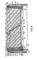
- the geometry of the inner shell 48 and the disposition of its longitudinal axis 62 relative to the longitudinal axis of the neck plug 40 is not critical to the invention. Accordingly, the inner shell 48 is preferably slightly tapered during vacuum forming to facilitate the insertion of the neck plug 40 which can also be vacuum formed.
- the neck plug 40 need not be concentric with the outer shell 50.
- Each section 35 and 36 of the neck plug 40 has a gasket 70 and 72 located beneath the rims 49 and 51 of the cover plates 43 and 45 respectively. Gaskets 70 and 72 seal the space 73 between the inner shell 48 and the periphery of each section 35 and 36 of the neck plug 40.
- a plurality of spacer elements 75 radially extend from the outer shell 50 of the neck tube adapter 42 a distance substantially equal to the width of the clearance space 27.
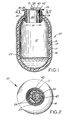
- the spacer elements 75 are intended to function in a manner equivalent to the counterpart spacer elements 26 of Figures 1 and 2, although of substantially different geometry.
- the spacer elements 75 may have any desired shape but are preferably formed as raised dimples extending from the outer shell 50 as an integral component thereof.
- the spacer elements 75 may be arranged in any desired pattern so long as they are distributed around the circumference of the outer shell 50 to assure an annular clearance 27 between the outer shell 50 and the neck tube 20. As explained in connection with Figures 1 and 2, any arrangement of spacer elements 75 may be used and any number, provided in total they occupy a minimum of the annular space 27 by volume.
Landscapes
- Engineering & Computer Science (AREA)
- Mechanical Engineering (AREA)
- General Engineering & Computer Science (AREA)
- Filling Or Discharging Of Gas Storage Vessels (AREA)
- Packages (AREA)
Claims (8)
Priority Applications (1)
| Application Number | Priority Date | Filing Date | Title |
|---|---|---|---|
| AT83401666T ATE30352T1 (de) | 1982-08-17 | 1983-08-16 | Fuellrohrverschlussanordnung fuer kryogene behaelter. |
Applications Claiming Priority (2)
| Application Number | Priority Date | Filing Date | Title |
|---|---|---|---|
| US06/408,915 US4411138A (en) | 1982-08-17 | 1982-08-17 | Neck tube closure assembly for cryogenic containers |
| US408915 | 1995-03-22 |
Publications (3)
| Publication Number | Publication Date |
|---|---|
| EP0106715A2 EP0106715A2 (fr) | 1984-04-25 |
| EP0106715A3 EP0106715A3 (en) | 1984-12-27 |
| EP0106715B1 true EP0106715B1 (fr) | 1987-10-21 |
Family
ID=23618300
Family Applications (1)
| Application Number | Title | Priority Date | Filing Date |
|---|---|---|---|
| EP83401666A Expired EP0106715B1 (fr) | 1982-08-17 | 1983-08-16 | Assemblage de bouchage pour le col des récipients cryogéniques |
Country Status (6)
| Country | Link |
|---|---|
| US (1) | US4411138A (fr) |
| EP (1) | EP0106715B1 (fr) |
| AT (1) | ATE30352T1 (fr) |
| BR (1) | BR8304309A (fr) |
| CA (1) | CA1226554A (fr) |
| DE (1) | DE3374147D1 (fr) |
Cited By (1)
| Publication number | Priority date | Publication date | Assignee | Title |
|---|---|---|---|---|
| WO2022241089A1 (fr) * | 2021-05-12 | 2022-11-17 | Biolife Solutions, Inc. | Récipient de stockage cryogénique, élément de fermeture et procédé de fabrication |
Families Citing this family (21)
| Publication number | Priority date | Publication date | Assignee | Title |
|---|---|---|---|---|
| US4472946A (en) * | 1983-01-28 | 1984-09-25 | Zwick Eugene B | Cryogenic storage tank with built-in pump |
| FR2614607B1 (fr) * | 1987-04-30 | 1989-07-13 | Air Liquide | Dispositif d'obturation pour recipient cryogenique |
| DE3717053A1 (de) * | 1987-05-21 | 1988-12-01 | Messer Griesheim Gmbh | Verschluss fuer einen auslaufsicheren kryobehaelter |
| US6230500B1 (en) | 1999-09-29 | 2001-05-15 | Mve, Inc. | Cryogenic freezer |
| US6467642B2 (en) | 2000-12-29 | 2002-10-22 | Patrick L. Mullens | Cryogenic shipping container |
| EP1356229A4 (fr) * | 2000-12-29 | 2009-11-18 | Cryoport Systems Llc | Conteneur d'expedition cryogenique |
| US6568194B1 (en) * | 2001-01-17 | 2003-05-27 | Superconductor Technologies, Inc. | Evacuation port and closure for dewars |
| US6539726B2 (en) | 2001-05-08 | 2003-04-01 | R. Kevin Giesy | Vapor plug for cryogenic storage vessels |
| WO2003044424A2 (fr) * | 2001-11-21 | 2003-05-30 | Oxford Magnet Technology Limited | Assemblage cryogenique |
| JP6134211B2 (ja) * | 2013-06-19 | 2017-05-24 | 川崎重工業株式会社 | 二重殻タンクおよび液化ガス運搬船 |
| DE202016104705U1 (de) * | 2016-08-26 | 2017-11-29 | abh Ingenieur-Technik GmbH | Thermobehälter für temperatursensible Fluide |
| DE102017205279B3 (de) * | 2017-03-29 | 2018-09-20 | Bruker Biospin Ag | Kryostatanordnung mit einem Halsrohr mit einer tragenden Struktur und ein die tragende Struktur umgebendes Außenrohr zur Verringerung des Kryogenverbrauchs |
| US10945919B2 (en) | 2017-12-13 | 2021-03-16 | Cryoport, Inc. | Cryocassette |
| US11268655B2 (en) | 2018-01-09 | 2022-03-08 | Cryoport, Inc. | Cryosphere |
| US12025276B2 (en) | 2018-01-09 | 2024-07-02 | Cryoport, Inc. | Cryosphere |
| CN112654566B (zh) * | 2018-06-18 | 2023-06-30 | 快欧泊特股份有限公司 | 低温衬里 |
| US10859211B2 (en) | 2018-07-02 | 2020-12-08 | Cryoport, Inc. | Segmented vapor plug |
| US11691788B1 (en) | 2022-01-20 | 2023-07-04 | Cryoport, Inc. | Foldable cassette bags for transporting biomaterials |
| US12186268B2 (en) | 2022-01-20 | 2025-01-07 | Cryoport, Inc. | Foldable cassette bags for transporting biomaterials |
| US12280008B2 (en) | 2022-04-07 | 2025-04-22 | Cryoport, Inc. | Systems and devices for transporting biomaterials |
| US12383465B2 (en) | 2022-06-29 | 2025-08-12 | Cryoport, Inc. | Cassette bags for transporting biomaterials |
Family Cites Families (12)
| Publication number | Priority date | Publication date | Assignee | Title |
|---|---|---|---|---|
| US1654474A (en) * | 1922-12-26 | 1927-12-27 | R C Headley | Breather-pipe cap |
| US2648953A (en) * | 1951-06-22 | 1953-08-18 | Hofman Lab Inc | Liquid helium container with insertable heat exchanger |
| FR1129685A (fr) * | 1955-07-13 | 1957-01-24 | Jose Jano Ets | Bague de bouchon pour bouteilles et autres récipients à goulot |
| FR1237018A (fr) * | 1958-10-06 | 1960-11-23 | Union Carbide Corp | Récipient à double paroi pour gaz liquéfiés |
| GB917300A (en) * | 1959-09-02 | 1963-01-30 | Harry Jock Freestone | Improved closure for containers |
| NL271916A (fr) * | 1960-12-05 | |||
| US3168362A (en) * | 1962-02-01 | 1965-02-02 | Union Carbide Corp | Thermally insulated bulk storage container |
| GB997427A (en) * | 1963-06-18 | 1965-07-07 | Ceeco Products Pty Ltd | Bottle stoppers |
| FR1587504A (fr) * | 1968-10-14 | 1970-03-20 | ||
| SU549147A1 (ru) * | 1973-10-25 | 1977-03-05 | Предприятие П/Я В-2572 | Сосуд дл хранени биопродуктов при низких температурах |
| US3910441A (en) * | 1974-02-28 | 1975-10-07 | Aladdin Ind Inc | Vacuum insulated bottle |
| GB2052710A (en) * | 1979-06-22 | 1981-01-28 | Morozov V | Cryogenic Container |
-
1982
- 1982-08-17 US US06/408,915 patent/US4411138A/en not_active Expired - Fee Related
-
1983
- 1983-08-10 CA CA000434268A patent/CA1226554A/fr not_active Expired
- 1983-08-11 BR BR8304309A patent/BR8304309A/pt unknown
- 1983-08-16 EP EP83401666A patent/EP0106715B1/fr not_active Expired
- 1983-08-16 AT AT83401666T patent/ATE30352T1/de not_active IP Right Cessation
- 1983-08-16 DE DE8383401666T patent/DE3374147D1/de not_active Expired
Cited By (1)
| Publication number | Priority date | Publication date | Assignee | Title |
|---|---|---|---|---|
| WO2022241089A1 (fr) * | 2021-05-12 | 2022-11-17 | Biolife Solutions, Inc. | Récipient de stockage cryogénique, élément de fermeture et procédé de fabrication |
Also Published As
| Publication number | Publication date |
|---|---|
| EP0106715A3 (en) | 1984-12-27 |
| EP0106715A2 (fr) | 1984-04-25 |
| CA1226554A (fr) | 1987-09-08 |
| ATE30352T1 (de) | 1987-11-15 |
| US4411138A (en) | 1983-10-25 |
| DE3374147D1 (en) | 1987-11-26 |
| BR8304309A (pt) | 1984-03-20 |
Similar Documents
| Publication | Publication Date | Title |
|---|---|---|
| EP0106715B1 (fr) | Assemblage de bouchage pour le col des récipients cryogéniques | |
| US4803343A (en) | Electric fluid heating apparatus utilizing a vaporizable working fluid | |
| US3168362A (en) | Thermally insulated bulk storage container | |
| US4313400A (en) | Lined metal tank with heat shield, indirect fired water heater and method of making same | |
| US3066222A (en) | Infra-red detection apparatus | |
| US2986891A (en) | Low-temperature vessels | |
| US20190137163A1 (en) | Cryogenic Freezer | |
| US2492788A (en) | Regenerator | |
| US4096707A (en) | Portable refrigeration machine | |
| JPS6294769A (ja) | 二段熱カツプリング | |
| KR102282181B1 (ko) | 직냉식 액화장치 | |
| US4827737A (en) | Cold reserving apparatus | |
| US3208622A (en) | Double-walled container | |
| US3224212A (en) | Process and apparatus for continuously dehydrating gas | |
| KR102772049B1 (ko) | 액화기 단열 시스템 및 이를 적용한 액화기 | |
| EP3467408B1 (fr) | Méthode de fonctionnement d'une installation de stockage à basse température ayant un appareil de retrait d'azote dans un bâtiment | |
| US3693374A (en) | Variable temperature cooling apparatus | |
| US2555502A (en) | Method of freezing food | |
| US3436926A (en) | Refrigerating structure for cryostats | |
| US2049779A (en) | Refrigerating package | |
| US4364235A (en) | Helium-cooled cold surface, especially for a cryopump | |
| US1844677A (en) | Refrigeration | |
| SU994861A1 (ru) | Сосуд криобиологический | |
| CN218432763U (zh) | 一种用于肿瘤标志物抗体原材料的保存设备 | |
| JPH0136067Y2 (fr) |
Legal Events
| Date | Code | Title | Description |
|---|---|---|---|
| PUAI | Public reference made under article 153(3) epc to a published international application that has entered the european phase |
Free format text: ORIGINAL CODE: 0009012 |
|
| AK | Designated contracting states |
Designated state(s): AT BE CH DE FR GB IT LI LU NL SE |
|
| PUAL | Search report despatched |
Free format text: ORIGINAL CODE: 0009013 |
|
| AK | Designated contracting states |
Designated state(s): AT BE CH DE FR GB IT LI LU NL SE |
|
| 17P | Request for examination filed |
Effective date: 19850506 |
|
| GRAA | (expected) grant |
Free format text: ORIGINAL CODE: 0009210 |
|
| AK | Designated contracting states |
Kind code of ref document: B1 Designated state(s): AT BE CH DE FR GB IT LI LU NL SE |
|
| PG25 | Lapsed in a contracting state [announced via postgrant information from national office to epo] |
Ref country code: NL Effective date: 19871021 Ref country code: LI Effective date: 19871021 Ref country code: IT Free format text: LAPSE BECAUSE OF FAILURE TO SUBMIT A TRANSLATION OF THE DESCRIPTION OR TO PAY THE FEE WITHIN THE PRESCRIBED TIME-LIMIT;WARNING: LAPSES OF ITALIAN PATENTS WITH EFFECTIVE DATE BEFORE 2007 MAY HAVE OCCURRED AT ANY TIME BEFORE 2007. THE CORRECT EFFECTIVE DATE MAY BE DIFFERENT FROM THE ONE RECORDED. Effective date: 19871021 Ref country code: FR Free format text: THE PATENT HAS BEEN ANNULLED BY A DECISION OF A NATIONAL AUTHORITY Effective date: 19871021 Ref country code: CH Effective date: 19871021 Ref country code: BE Effective date: 19871021 Ref country code: AT Effective date: 19871021 |
|
| REF | Corresponds to: |
Ref document number: 30352 Country of ref document: AT Date of ref document: 19871115 Kind code of ref document: T |
|
| PG25 | Lapsed in a contracting state [announced via postgrant information from national office to epo] |
Ref country code: SE Effective date: 19871031 |
|
| REF | Corresponds to: |
Ref document number: 3374147 Country of ref document: DE Date of ref document: 19871126 |
|
| REG | Reference to a national code |
Ref country code: CH Ref legal event code: PL |
|
| EN | Fr: translation not filed | ||
| NLV1 | Nl: lapsed or annulled due to failure to fulfill the requirements of art. 29p and 29m of the patents act | ||
| PG25 | Lapsed in a contracting state [announced via postgrant information from national office to epo] |
Ref country code: GB Free format text: LAPSE BECAUSE OF NON-PAYMENT OF DUE FEES Effective date: 19880816 |
|
| PLBE | No opposition filed within time limit |
Free format text: ORIGINAL CODE: 0009261 |
|
| STAA | Information on the status of an ep patent application or granted ep patent |
Free format text: STATUS: NO OPPOSITION FILED WITHIN TIME LIMIT |
|
| PG25 | Lapsed in a contracting state [announced via postgrant information from national office to epo] |
Ref country code: LU Free format text: LAPSE BECAUSE OF NON-PAYMENT OF DUE FEES Effective date: 19880831 |
|
| 26N | No opposition filed | ||
| PG25 | Lapsed in a contracting state [announced via postgrant information from national office to epo] |
Ref country code: DE Effective date: 19890503 |
|
| GBPC | Gb: european patent ceased through non-payment of renewal fee | ||
| ITTA | It: last paid annual fee |