EP0106625A2 - Strip wound tubular bodies with light weight core - Google Patents
Strip wound tubular bodies with light weight core Download PDFInfo
- Publication number
- EP0106625A2 EP0106625A2 EP83306027A EP83306027A EP0106625A2 EP 0106625 A2 EP0106625 A2 EP 0106625A2 EP 83306027 A EP83306027 A EP 83306027A EP 83306027 A EP83306027 A EP 83306027A EP 0106625 A2 EP0106625 A2 EP 0106625A2
- Authority
- EP
- European Patent Office
- Prior art keywords
- strip
- rib section
- adhesive
- tube
- section
- Prior art date
- Legal status (The legal status is an assumption and is not a legal conclusion. Google has not performed a legal analysis and makes no representation as to the accuracy of the status listed.)
- Withdrawn
Links
Images

Classifications
-
- F—MECHANICAL ENGINEERING; LIGHTING; HEATING; WEAPONS; BLASTING
- F02—COMBUSTION ENGINES; HOT-GAS OR COMBUSTION-PRODUCT ENGINE PLANTS
- F02K—JET-PROPULSION PLANTS
- F02K9/00—Rocket-engine plants, i.e. plants carrying both fuel and oxidant therefor; Control thereof
- F02K9/08—Rocket-engine plants, i.e. plants carrying both fuel and oxidant therefor; Control thereof using solid propellants
- F02K9/32—Constructional parts; Details not otherwise provided for
- F02K9/34—Casings; Combustion chambers; Liners thereof
-
- B—PERFORMING OPERATIONS; TRANSPORTING
- B21—MECHANICAL METAL-WORKING WITHOUT ESSENTIALLY REMOVING MATERIAL; PUNCHING METAL
- B21C—MANUFACTURE OF METAL SHEETS, WIRE, RODS, TUBES OR PROFILES, OTHERWISE THAN BY ROLLING; AUXILIARY OPERATIONS USED IN CONNECTION WITH METAL-WORKING WITHOUT ESSENTIALLY REMOVING MATERIAL
- B21C37/00—Manufacture of metal sheets, bars, wire, tubes or like semi-manufactured products, not otherwise provided for; Manufacture of tubes of special shape
- B21C37/06—Manufacture of metal sheets, bars, wire, tubes or like semi-manufactured products, not otherwise provided for; Manufacture of tubes of special shape of tubes or metal hoses; Combined procedures for making tubes, e.g. for making multi-wall tubes
- B21C37/15—Making tubes of special shape; Making tube fittings
- B21C37/154—Making multi-wall tubes
-
- F—MECHANICAL ENGINEERING; LIGHTING; HEATING; WEAPONS; BLASTING
- F16—ENGINEERING ELEMENTS AND UNITS; GENERAL MEASURES FOR PRODUCING AND MAINTAINING EFFECTIVE FUNCTIONING OF MACHINES OR INSTALLATIONS; THERMAL INSULATION IN GENERAL
- F16L—PIPES; JOINTS OR FITTINGS FOR PIPES; SUPPORTS FOR PIPES, CABLES OR PROTECTIVE TUBING; MEANS FOR THERMAL INSULATION IN GENERAL
- F16L9/00—Rigid pipes
- F16L9/02—Rigid pipes of metal
- F16L9/04—Reinforced pipes
Definitions
- This invention relates to tubular bodies formed by winding metal strips about a mandrel and suitable for use as rocket motor cases missile canisters, and other such tubular vessels where tube wall strength and weight are important.
- Strip-winding is an established art for making metal tubes suitable for such applications as rocket motor cases. See, for example, U.S. Patents 3,044,256 and 3,230,122 as well as UK Patents 747,194; 884,578 and 898,195, which disclose tubular metal bodies formed of a.plurality of adhesively bonded layers of helically-wound strip metal, in which adjacent edges of the metal strip in one layer are displaced with reference to adjacent edges of the strip in an adjacent layer so as to avoid any alignment of mating edges in adjacent layers.
- the strip winding process as described in these patents forms precisely round and straight tubes at low cost. When high-strength steel strips are used, the resulting thin-walled, high-performance tubes are light in weight and competitive on a cost basis with filament reinforced composite tubes.
- a cylindrical tubular metal body that has increased resistance to buckling without undue weight penalties, that is less vulnerable to impact damage, and that can be supplied with integral end fittings, includes a tube of known construction formed of a plurality of adhesively bonded layers of helically-wound strip metal, (in which adjacent edges of the metal strip in one layer are displaced with reference to adjacent edges of the strip in an adjacent layer so as to avoid any alignment of mating edges in adjacent layers),-and it is characterized in that the outer surface of the tube is surrounded by and adhesively bonded to a cylindrical rib section having a cellular structure, and the rib section is surrounded by a second tube having the same structure as the other tube and having its plurality of strip metal layers helically wound around the rib section, each of the tubes having a radial dimension that is less than that of the rib section and a weight that is greater than that of the rib section.
- the addition of the rib section and a second strip-wound tube according to the invention dramatically improves the wall buckling resistance of the tubular bodies as compared to a minimal weight increase resulting from its use.
- the preferred materials suitable for the rib section are formable metallic honeycomb having hexagonal or rectilinear cells.
- the bonding between the tubes and the rib section contains adhesive from a layer of strip wound tape adhesive.
- Metal strip 15 the edges of which are spaced by a gap 17, spirals about the central longitudinal axis 11 of canister barrel 10 as is depicted in Figure 1.
- This continuous strip 15 is the exterior of the outer cylindrical strip wound section of canister barrel 10.
- Figure 2 is a typical cross-section of the wall 18 of canister barrel 10. Shown in Figure 2 are sections of metal strips 15, 19 and 21 which strips make up the aforementioned strip wound, outer cylindrical section designated as 30. Also seen in this cross-section of wall 18 is inner cylindrical section 26, made up of strips 23, 25 and 27.
- the metal strips 15, 19, 21, 23, 25 and 27 each consist of a single strip of metal. Gaps 17, 17A and 17B spiral about the tube section 14 in each of the respective planes of the strips 15, 19 and 21. Likewise, gaps 17C, 17D and 17E are between the respective adjacent edges of each of the strips 23, 25 and 27 and spiral about the tube section 14 in each of the three cylindrical planes of these strips 23, 25 and 27. Gaps 17, 17A, 17B, 17C, 17D, 17E each contain adhesive.
- Honeycomb 28 is sandwiched between cylindrical sections 26 and 30 of the aforementioned metal strips.
- wall 18 as shown in Figure 2 further comprises rubber insulator 24 and fluorinated hydrocarbon liner 22 adhesively bonded thereto. Liner 22 and the rubber insulator 24 are concentric inside tube section 14 between its ends 13, 31.
- Figures 3-6 are additional cross sectional views of canister barrel 10 shown in Figure 1. In the drawings of Figures 3-6, however, the gaps 17, 17A, 17B, 17C, 17D, and 17E are not illustrated for simplicity.
- Figure 3 is a cross section of the aft end 13 of tubular section 14.
- the wall 18 at the aftmost part of this aft end 13 comprises cylindrical metal sleeve 20, inner, cylindrical section 26, cylindrical spacer 29 and outer, cylindrical section 30.
- Metal sleeve 20 in Figure 3 is a hollow tube having inner and outer surfaces, the outer of which surfaces is bonded to the contiguous, inner surface of strip windings 26, i.e. strip 23 depicted in Figure 2.
- Metal sleeve 20 serves as a rigid core for mounting an end group fitting to this aftmost end of tube section 14. Forward of cylindrical metal sleeve 20 and extending around the inside of tubular section 14 are the adhesively bonded together liner 22 and insulator 24. The outer surface of insulator 24 is adhesively bonded to the inner surface of strip 23.
- Figure 4 is a cross section of the forward end of canister barrel 10 and shows the mounting of diaphram flange 12 to tube section 14.
- This forward end of tube section 14 comprises the liner 22, the rubber insulator 24, the three strip wound metal layers of inner cylindrical section 26 and the three strip wound layers of outer cylindrical section 30. Bonded between these strip wound layers is honeycomb 28 and at the forward most part of forward end 31, the metallic sleeve 32.
- Sleeve 32 has mounting holes, e.g. 34 for bolting diaphram flange 12 to tube section 14 by means of bolt such as 37 (not shown in Figure 1).
- Diaphram flange 12 serves to retain a sealing flange for closing the end 31 of canister barrel 10. If desired, the cylindrical portion 35 of flange 12 can serve as sleeve 32, thereby reducing the complexity of this end fitting.
- Figures 5 and 6 show the region of canister barrel 10 which is cut out to allow antenna placement in connection with canister deployment.
- Antenna mounting flange 36 is added to canister barrel 10 during fabrication thereof.
- Mounting flange 36 has a thickness corresponding to that.of honeycomb 28 and a curvature corresponding to that of the cylindrical strip wound section 26, as seen better in Figure 56.
- Holes 3 8 serve for mounting the antenna assembly (not shown).
- the hexagonal cell structure of honeycomb 28 is shown in Figure 5.
- each of the several metal strips is wound about a mandrel at an angle A wherein the angle A is defined as the angle between the intersection of (a) the longitudinal centerline of the strip being layed on the mandrel and (b) a line which is both parallel to the central longitudinal axis of the mandrel and coincident with the surface on which the strip is being layed.
- W is the strip width
- G is the distance or gap between the adjacent edges of the strip that is to be wound about the mandrel
- C is the circumference of the winding surface, i.e.
- the width W of the strip is dependent on the strip material chosen; the circumference C is also fixed by the tube diameter desired; and the gap G is typically selected to be between 30 and 50 mils, e.g. 40 mils, for tubular bodies such as canister barrel 10 herein before discussed.
- a lathe type applicator carries a rotatable spool of the metal strip.
- the lathe applicator translates along the longitudinal axis of a mandrel while the mandrel rotates at a speed so coordinated therewith that adjacent edges of the strip are layed with the gap G therebetween.
- the lathe type applicator has translated the distance W+G along the central longitudinal sin A axis of the mandrel, where W, G and A are hereinbefore defined. This results in the gap G of consistent dimension spiraling around the mandrel in the plane of each of the strip wound layers.
- an aluminum mandrel is preferably selected, particularly when adhesive tape, as hereinafter disclosed, is used in the fabrication. If the finished tube is to be insulated by an insulator/liner combination such as 22,24 of canister barrel 10, then these are preferably layed on the mandrel using conventional techniques prior to strip winding. Alternatively, insulator 22, 24 may be omitted or added after the strip winding operations.
- Each metal strip that is wound around the mandrel may be coated with adhesive, or, alternatively, layed on a layer of strip wound adhesive.
- the strip wound adhesive comprises B-staged adhesive in the form of a tape which is spiraled around in the mandrel to form an adhesive layer.
- a layer of adhesive is first wound around the rubber insulator 24. Then, the strip wound metal layer 23 is wound about this adhesive layer followed by winding of additional tape adhesive layer and then strip wound metal layer 25.
- the rib section such as honeycomb 28 is layed thereabout. If tape adhesive is used, then this tape is first layed on the outer surface of the inner cylindrical strip wound section prior to adding the rib section. The rib section is formed over this adhesive tape layer and then another adhesive tape layer is layed on the rib section.
- the outer cylindrical strip wound section such as 30 in Figure 2-6 is then wound about the rib section in the manner as described in connection with the inner cylindrical strip wound section, i.e. alternating layers of metal and adhesive where the adhesive may be coated onto the metal strip as it is layed or added as a separate layer.
- the outer surface of the final strip wound layer e.g. strip 15 of Figures 1-6, does not require adhesive.
- room temperature adhesives can be used. These adhesives are coated onto each of the strips and the rib section during the winding operation. Similarly, the cylindrical sleeves are also coated during this operation.
- the uncured or partially cured strip wolnd tubular body is heated to the requisite curing temperature (e.g. above 200°F.) for a time sufficient to cure the adhesive.
- the requisite curing temperature e.g. above 200°F.
- Use of aluminum mandrels are advantageous in this regard because they expand to a greater extent than heated steel strip wound tubular bodies thereby enabling fascile removal of the tubular body upon cool down after cure. Heating of the aluminum mandrel from within is preferred because the inner cylindrical strip wound section expands first and fixes the rib section, e.g. honeycomb section - 28 of Figures 2-6, between the outer and inner cylindrical strip wound sections.
- the inner rib section is selected to withstand these curing stresses.
- the honeycomb 28 of canister barrel 10 has a crush strength of 850 psi with a stabilized compressive strength of 1300 psi.
- suitable metal honeycombs are the Shapegrip honeycombs from American Cyanamid made of, for example, 5052 or 2025 aluminum and the Hexcel rectilinear honeycombs Flex-Core, Ox-Core and Tube-Core.
- Stainless steel honeycomb are advantageous from a corrosion standpoint when the strip windings also are made of steel.
- Typical cells of the honeycombs suitable for this invention include those with areas between about 0.01 and 0.05 square inches.
- chains, nets, foams and the like of various configurations and cell sizes can be used as the rib section in practice of this invention providing they have adequate crush strengths to withstand cure and meet the requirements of the specific application for the tubular body.
- rigid plastic foams such as Rohacell from Cyro Industries, a rigid polymethacrylimide foam, can be shaped to serve as the rib section for the tubular bodies of this invention.
- the adhesive accounts for about 10% by weight of the final tube.
- Use of liquid adhesives can reduce this amount to about 5% by weight, these percentages being based on a tube having six primed, stainless steel strip wound layers and Shapegrid honeycomb as described in connection with Figure 1-6.
- such a tube has a total of between about 0.040 and 0.060 inch thick of strip wound adhesive resulting from six layers of nominally 0.01 inch thick strip adhesive as layed or between about 0.020 and 0.30 inch thick cured liquid adhesive resulting from six layers of nominally 0.005 inch liquid adhesive as layed.
- Rib sections are advantageous in that there is electrical continuity thereby established between the strip wound sections in the finished tubular bodies thereby.
- Rib sections fabricated from other materials, e.g. filamentary composite, thermoplastic or thermosetting resins, can also be used where this electrical continuity is unnecessary or otherwise provided for.
- a strip wound canister barrel prototype is made.
- the forward end of the barrel is made to have a four (4) inch long split cylindrical spacer.
- the spacer is made of grit blasted aluminum and circumferentially banded in place to close the axially extending splitline.
- the honeycomb material is Shapegrip from American Cyanamid (hexagonal cells) and like the spacer is 0.125 inches thick.
- the cells of this honeycomb have an area of about 0.025 square inches.
- the wall thickness of the honeycomb cells is about 3 mils.
- the aluminum honeycomb is preformed into two 180° half cylindrical sections which result in a cylindrical honeycomb 72 inches long and 20 inches in diameter.
- the adhesive used is FM53 (American Cyanamid) of 4 inch wide paper covered partially cured epoxy tape adhesive.
- the high strength steel strips are grit blasted, primed, and 3.96 + 0.008 inches wide and about 11 mils thick.
- the finished prototype tube weighs 92 pounds and has a wall thickness of approximately 0.240 inches.
- the prototype tube is made using a lathe type strip applicator.
- the strip contact pressure is 3.28 psig resulting from a 130 lb strip winding tension for each of the six strips in the pair of radially spaced cylindrical sections.
- the mandrel is aluminum and cure of the adhesive is at 260°F. Some increase in the gap between the adjacent edges of the strip is noted after cure.
- the gaps of the exterior strips range from zero to about 0.140 inches with a typical gap of 0.070 inches.
Abstract
An improved strip wound tubular body is disclosed in which a rib section is carried between concentric cylindrical sections of metal strip windings. The rib section dramatically increases wall buckling resistance without significantly adding to the weight of the tube. The improved tubular body is particularly useful for rocket motor canisters and cases.
Manufacture of the improved tubular bodies is also disclosed. The manufacture includes adhesively bonding the strip windings and rib section together with curable adhesive. Use of an aluminum mandrel heated from inside to effect the cure of high temperature adhesive is disclosed. Heating from within the mandrel fixes the rib section during such a cure. Use of liquid adhesive in the manufacture is also disclosed. The liquid adhesive may be a room temperature adhesive.
Description
- This invention relates to tubular bodies formed by winding metal strips about a mandrel and suitable for use as rocket motor cases missile canisters, and other such tubular vessels where tube wall strength and weight are important.
- Strip-winding is an established art for making metal tubes suitable for such applications as rocket motor cases. See, for example, U.S. Patents 3,044,256 and 3,230,122 as well as UK Patents 747,194; 884,578 and 898,195, which disclose tubular metal bodies formed of a.plurality of adhesively bonded layers of helically-wound strip metal, in which adjacent edges of the metal strip in one layer are displaced with reference to adjacent edges of the strip in an adjacent layer so as to avoid any alignment of mating edges in adjacent layers. The strip winding process as described in these patents forms precisely round and straight tubes at low cost. When high-strength steel strips are used, the resulting thin-walled, high-performance tubes are light in weight and competitive on a cost basis with filament reinforced composite tubes.
- However, many applications of light weight tubes also require that the tubes resist substantial wall buckling forces. Such resistance is proportional to the wall thickness cubed. Conventional strip wound tubes are unsuited to these applications because when additional layers of the steel strips are added to achieve sufficient buckling resistance, the corresponding increases in weight and cost render the finished tubes uncompetitive.
- Conventional thin-walled strip-wound tubes are also subject to denting, puncture or other potentially serious damage from impact with hard objects. Such vulnerability increases the hazards of deploying canisters or rockets that employ these tubes and reduces their reliability. It would be desirable, to increase the impact resistance of strip-wound tubes or at least to minimize the effects of such impacts.
- Also it would be desirable, in many circumstances, to have the end fittings for connections to other bodies integrally attached or attachable without increasing the diameter of the finished tube, instead of being applied to the surface of the strip-wound tubes according to conventional practice.
- According to the invention, a cylindrical tubular metal body that has increased resistance to buckling without undue weight penalties, that is less vulnerable to impact damage, and that can be supplied with integral end fittings, includes a tube of known construction formed of a plurality of adhesively bonded layers of helically-wound strip metal, (in which adjacent edges of the metal strip in one layer are displaced with reference to adjacent edges of the strip in an adjacent layer so as to avoid any alignment of mating edges in adjacent layers),-and it is characterized in that the outer surface of the tube is surrounded by and adhesively bonded to a cylindrical rib section having a cellular structure, and the rib section is surrounded by a second tube having the same structure as the other tube and having its plurality of strip metal layers helically wound around the rib section, each of the tubes having a radial dimension that is less than that of the rib section and a weight that is greater than that of the rib section.
- The addition of the rib section and a second strip-wound tube according to the invention dramatically improves the wall buckling resistance of the tubular bodies as compared to a minimal weight increase resulting from its use. The preferred materials suitable for the rib section are formable metallic honeycomb having hexagonal or rectilinear cells.
- Preferably, the bonding between the tubes and the rib section contains adhesive from a layer of strip wound tape adhesive.
-
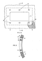
- Figure 1 is a perspective of the strip wound canister barrel 10 of this invention. The drawing shows the canister barrel 10 broken away between its
ends - Figure 2 is an enlarged cross-section of the wall of the canister barrel of Figure 1 taken along 2-2 of Figure 1.
- Figures 3 and 4 are cross-sections of the aft and
forward ends - Figures 5 and 6 show respectively the antenna housing of the canister barrel in elevation and in the cross-section taken along 6-6 of Figure 5.
- Figure 1 schematically depicts, in perspective, a canister barrel 10 according to this invention. The canister barrel 10 represents the launch canister for a strategic missile, without such conventional canister assembly items as the forward seal and the antenna assembly. The canister barrel 10 has a
diaphram mounting flange 12 bolted totubular section 14 at theforward end 31. -Holes 16 through the other (aft) .end 13 oftube section 14 permit attachment to a support such as the bulkhead of a vessel. -
Metal strip 15, the edges of which are spaced by agap 17, spirals about the central longitudinal axis 11 of canister barrel 10 as is depicted in Figure 1. Thiscontinuous strip 15 is the exterior of the outer cylindrical strip wound section of canister barrel 10. - Figure 2 is a typical cross-section of the
wall 18 of canister barrel 10. Shown in Figure 2 are sections ofmetal strips wall 18 is innercylindrical section 26, made up ofstrips - The
metal strips Gaps tube section 14 in each of the respective planes of thestrips gaps strips tube section 14 in each of the three cylindrical planes of thesestrips Gaps - Honeycomb 28 is sandwiched between cylindrical sections 26 and 30 of the aforementioned metal strips. In addition,
wall 18 as shown in Figure 2 further comprisesrubber insulator 24 and fluorinatedhydrocarbon liner 22 adhesively bonded thereto.Liner 22 and therubber insulator 24 are concentric insidetube section 14 between itsends - Figures 3-6 are additional cross sectional views of canister barrel 10 shown in Figure 1. In the drawings of Figures 3-6, however, the
gaps - Figure 3 is a cross section of the
aft end 13 oftubular section 14. Thewall 18 at the aftmost part of thisaft end 13 comprisescylindrical metal sleeve 20, inner,cylindrical section 26,cylindrical spacer 29 and outer,cylindrical section 30. -
Metal sleeve 20 in Figure 3 is a hollow tube having inner and outer surfaces, the outer of which surfaces is bonded to the contiguous, inner surface ofstrip windings 26, i.e.strip 23 depicted in Figure 2.Metal sleeve 20 serves as a rigid core for mounting an end group fitting to this aftmost end oftube section 14. Forward ofcylindrical metal sleeve 20 and extending around the inside oftubular section 14 are the adhesively bonded togetherliner 22 andinsulator 24. The outer surface ofinsulator 24 is adhesively bonded to the inner surface ofstrip 23. - Figure 4 is a cross section of the forward end of canister barrel 10 and shows the mounting of
diaphram flange 12 totube section 14. This forward end oftube section 14 comprises theliner 22, therubber insulator 24, the three strip wound metal layers of innercylindrical section 26 and the three strip wound layers of outercylindrical section 30. Bonded between these strip wound layers ishoneycomb 28 and at the forward most part offorward end 31, themetallic sleeve 32.Sleeve 32 has mounting holes, e.g. 34 for boltingdiaphram flange 12 totube section 14 by means of bolt such as 37 (not shown in Figure 1). -
Diaphram flange 12 serves to retain a sealing flange for closing theend 31 of canister barrel 10. If desired, thecylindrical portion 35 offlange 12 can serve assleeve 32, thereby reducing the complexity of this end fitting. - Figures 5 and 6 show the region of canister barrel 10 which is cut out to allow antenna placement in connection with canister deployment.
Antenna mounting flange 36 is added to canister barrel 10 during fabrication thereof.Mounting flange 36 has a thickness corresponding to that.ofhoneycomb 28 and a curvature corresponding to that of the cylindricalstrip wound section 26, as seen better in Figure 56. Holes 38 serve for mounting the antenna assembly (not shown). The hexagonal cell structure ofhoneycomb 28 is shown in Figure 5. - In the process of making cylindrical strip sections such as 26,30 (as hereinbefore identified), each of the several metal strips is wound about a mandrel at an angle A wherein the angle A is defined as the angle between the intersection of (a) the longitudinal centerline of the strip being layed on the mandrel and (b) a line which is both parallel to the central longitudinal axis of the mandrel and coincident with the surface on which the strip is being layed. The angle A can be calculated by the relationship A = 90 - Arc Sin W+G . where W is the strip width; G is the distance or gap between the adjacent edges of the strip that is to be wound about the mandrel; and C is the circumference of the winding surface, i.e. mandrel plus any additional increase due to elastomer, other strip windings on the mandrel etc. The width W of the strip is dependent on the strip material chosen; the circumference C is also fixed by the tube diameter desired; and the gap G is typically selected to be between 30 and 50 mils, e.g. 40 mils, for tubular bodies such as canister barrel 10 herein before discussed.
- In a relatively simple practice of the process of this invention, a lathe type applicator carries a rotatable spool of the metal strip. The lathe applicator translates along the longitudinal axis of a mandrel while the mandrel rotates at a speed so coordinated therewith that adjacent edges of the strip are layed with the gap G therebetween. Thus, with each completed rotation of the mandrel, the lathe type applicator has translated the distance W+G along the central longitudinal sin A axis of the mandrel, where W, G and A are hereinbefore defined. This results in the gap G of consistent dimension spiraling around the mandrel in the plane of each of the strip wound layers.
- In fabrication of a canister barrel such as 10 of Figures 1-6, an aluminum mandrel is preferably selected, particularly when adhesive tape, as hereinafter disclosed, is used in the fabrication. If the finished tube is to be insulated by an insulator/liner combination such as 22,24 of canister barrel 10, then these are preferably layed on the mandrel using conventional techniques prior to strip winding. Alternatively,
insulator - Each metal strip that is wound around the mandrel may be coated with adhesive, or, alternatively, layed on a layer of strip wound adhesive. The strip wound adhesive comprises B-staged adhesive in the form of a tape which is spiraled around in the mandrel to form an adhesive layer. Thus, in forming an inner cylindrical, strip wound section such as 26 shown in Figure 2-6 using this tape adhesive, a layer of adhesive is first wound around the
rubber insulator 24. Then, the strip woundmetal layer 23 is wound about this adhesive layer followed by winding of additional tape adhesive layer and then strip woundmetal layer 25. - After the inner cylindrical strip wound section is wound, the rib section such as
honeycomb 28 is layed thereabout. If tape adhesive is used, then this tape is first layed on the outer surface of the inner cylindrical strip wound section prior to adding the rib section. The rib section is formed over this adhesive tape layer and then another adhesive tape layer is layed on the rib section. The outer cylindrical strip wound section such as 30 in Figure 2-6 is then wound about the rib section in the manner as described in connection with the inner cylindrical strip wound section, i.e. alternating layers of metal and adhesive where the adhesive may be coated onto the metal strip as it is layed or added as a separate layer. The outer surface of the final strip wound layer,e.g. strip 15 of Figures 1-6, does not require adhesive. - As an alternative to such tape adhesive that cures at elevated temperature, room temperature adhesives can be used. These adhesives are coated onto each of the strips and the rib section during the winding operation. Similarly, the cylindrical sleeves are also coated during this operation.
- When epoxy or other such high cure temperature tape adhesives are employed, the uncured or partially cured strip wolnd tubular body is heated to the requisite curing temperature (e.g. above 200°F.) for a time sufficient to cure the adhesive. Use of aluminum mandrels are advantageous in this regard because they expand to a greater extent than heated steel strip wound tubular bodies thereby enabling fascile removal of the tubular body upon cool down after cure. Heating of the aluminum mandrel from within is preferred because the inner cylindrical strip wound section expands first and fixes the rib section,
e.g. honeycomb section -28 of Figures 2-6, between the outer and inner cylindrical strip wound sections. - The inner rib section is selected to withstand these curing stresses. For example, the
honeycomb 28 of canister barrel 10 has a crush strength of 850 psi with a stabilized compressive strength of 1300 psi. Among the various honeycombs that can be used in practice of this invention are flexible honeycombs with diverse, e.g. hexagonal or recti- liner, cell configurations. Examples of suitable metal honeycombs are the Shapegrip honeycombs from American Cyanamid made of, for example, 5052 or 2025 aluminum and the Hexcel rectilinear honeycombs Flex-Core, Ox-Core and Tube-Core. Stainless steel honeycomb are advantageous from a corrosion standpoint when the strip windings also are made of steel. - Typical cells of the honeycombs suitable for this invention include those with areas between about 0.01 and 0.05 square inches. Moreover, chains, nets, foams and the like of various configurations and cell sizes can be used as the rib section in practice of this invention providing they have adequate crush strengths to withstand cure and meet the requirements of the specific application for the tubular body. For example, rigid plastic foams such as Rohacell from Cyro Industries, a rigid polymethacrylimide foam, can be shaped to serve as the rib section for the tubular bodies of this invention.
- When B-staged tape adhesive is used, the adhesive accounts for about 10% by weight of the final tube. Use of liquid adhesives, however, can reduce this amount to about 5% by weight, these percentages being based on a tube having six primed, stainless steel strip wound layers and Shapegrid honeycomb as described in connection with Figure 1-6. In this regard, such a tube has a total of between about 0.040 and 0.060 inch thick of strip wound adhesive resulting from six layers of nominally 0.01 inch thick strip adhesive as layed or between about 0.020 and 0.30 inch thick cured liquid adhesive resulting from six layers of nominally 0.005 inch liquid adhesive as layed.
- The use of metal rib sections is advantageous in that there is electrical continuity thereby established between the strip wound sections in the finished tubular bodies thereby. Rib sections fabricated from other materials, e.g. filamentary composite, thermoplastic or thermosetting resins, can also be used where this electrical continuity is unnecessary or otherwise provided for.
- The dramatic improvement in strip wound tubes of this invention is illustrated by calculations which show an 800% increase in tube wall buckling resistance in canister barrel 10, described above, with only a 3% weight increase when the
honeycomb 28 is 0.125 inches thick and made of Shapegrip hexagonal aluminum honeycomb having, a crush strength of 850 psi. This calculation is also based on high strength steel strips (290Ksi ultimate tensile strength) forstrips - Using the procedures as above described, a strip wound canister barrel prototype is made. The forward end of the barrel is made to have a four (4) inch long split cylindrical spacer. The spacer is made of grit blasted aluminum and circumferentially banded in place to close the axially extending splitline. The honeycomb material is Shapegrip from American Cyanamid (hexagonal cells) and like the spacer is 0.125 inches thick. The cells of this honeycomb have an area of about 0.025 square inches. The wall thickness of the honeycomb cells is about 3 mils. The aluminum honeycomb is preformed into two 180° half cylindrical sections which result in a cylindrical honeycomb 72 inches long and 20 inches in diameter. The adhesive used is FM53 (American Cyanamid) of 4 inch wide paper covered partially cured epoxy tape adhesive. The high strength steel strips are grit blasted, primed, and 3.96 + 0.008 inches wide and about 11 mils thick. The finished prototype tube weighs 92 pounds and has a wall thickness of approximately 0.240 inches.
- The prototype tube is made using a lathe type strip applicator. The strip contact pressure is 3.28 psig resulting from a 130 lb strip winding tension for each of the six strips in the pair of radially spaced cylindrical sections. The mandrel is aluminum and cure of the adhesive is at 260°F. Some increase in the gap between the adjacent edges of the strip is noted after cure. The gaps of the exterior strips range from zero to about 0.140 inches with a typical gap of 0.070 inches.
- After the canister barrel prototype is removed from the mandrel, its ends are cut off. The cut prototype.is measured with results shown as follows in Table I.

Claims (4)
1. A cylindrical tubular metal body including a tube formed of a plurality of adhesively bonded layers of helically-wound strip metal, adjacent edges of the metal strip in one layer being displaced with reference to adjacent edges of the strip in an adjacent layer so as to avoid any alignment of mating edges in adjacent layers, characterized in that the outer surface of the tube is surrounded by and adhesively bonded to a cylindrical rib section having a cellular structure, and the rib section is surrounded by a second tube having the same structure as the other tube and having its plurality of strip metal layers helically wound around the rib section, each of the tubes having a radial dimension that is less than that of the rib section and a weight that is greater than that of the rib section.
2. A cylindrical tubular metal body as claimed in claim 1, in which the cellular structure of the rib section adjacent one end of the metal body is replaced by a cylindrical metal sleeve having a wall thickness substantially equal to that of the rib section.
3. A cylindrical tubular metal body as claimed in claim 1 or 2, in which the rib section is a formable metallic honeycomb having hexagonal or rectilinear cells.
4. A cylindrical tubular metal body as claimed in claim 1, 2 or 3, in which the bonding between the tubes and the rib section contains adhesive from a layer of strip wound tape adhesive.
Applications Claiming Priority (2)
| Application Number | Priority Date | Filing Date | Title |
|---|---|---|---|
| US43318882A | 1982-10-06 | 1982-10-06 | |
| US433188 | 1995-05-03 |
Publications (2)
| Publication Number | Publication Date |
|---|---|
| EP0106625A2 true EP0106625A2 (en) | 1984-04-25 |
| EP0106625A3 EP0106625A3 (en) | 1986-09-10 |
Family
ID=23719175
Family Applications (1)
| Application Number | Title | Priority Date | Filing Date |
|---|---|---|---|
| EP83306027A Withdrawn EP0106625A3 (en) | 1982-10-06 | 1983-10-05 | Strip wound tubular bodies with light weight core |
Country Status (3)
| Country | Link |
|---|---|
| EP (1) | EP0106625A3 (en) |
| JP (1) | JPS59130627A (en) |
| NO (1) | NO833435L (en) |
Cited By (2)
| Publication number | Priority date | Publication date | Assignee | Title |
|---|---|---|---|---|
| US6457800B1 (en) * | 1997-12-04 | 2002-10-01 | Francotyp Postalia Ag & Co. K.G. | Method for tolerance compensation in an ink jet print head |
| WO2016030425A1 (en) * | 2014-08-27 | 2016-03-03 | Mahle International Gmbh | Method for the production of a tubular member, and tubular member |
Citations (9)
| Publication number | Priority date | Publication date | Assignee | Title |
|---|---|---|---|---|
| US2654686A (en) * | 1950-05-11 | 1953-10-06 | Northrop Aircraft Inc | Stiffened honeycomb core |
| FR1158007A (en) * | 1956-08-17 | 1958-06-06 | Fabrication De Tubes En Matier | tubular element with composite walls, process and equipment for its manufacture |
| FR1162692A (en) * | 1955-10-17 | 1958-09-16 | Solar Aircraft Co | Brazing process and equipment for the manufacture of composite elements with a honeycomb structure and products obtained by this process |
| GB898194A (en) * | 1954-12-22 | 1962-06-06 | Ici Ltd | Rocket motor casings |
| US3196533A (en) * | 1963-07-10 | 1965-07-27 | Martin Marietta Corp | Method for forming honeycomb materials |
| US3295279A (en) * | 1964-03-30 | 1967-01-03 | Midland Ross Corp | Laminated wall unit for cargo containers and other enclosures |
| US3345233A (en) * | 1963-11-06 | 1967-10-03 | Midland Ross Corp | Process for making circumambient wall unit |
| FR2376742A1 (en) * | 1977-01-10 | 1978-08-04 | Imp Metal Ind Kynoch Ltd | PROCESS FOR MANUFACTURING A STRUCTURE INCLUDING AT LEAST TWO TUBULAR LAYERS |
| DE2706899A1 (en) * | 1977-02-17 | 1978-08-31 | Muanyagipari Kutato Intezet | Reinforced tubes and containers having sandwich structure - produced by winding an inner layer, winding and gluing corrugated, glass-fibre reinforced tape over it, and curing |
-
1983
- 1983-09-23 NO NO833435A patent/NO833435L/en unknown
- 1983-10-05 EP EP83306027A patent/EP0106625A3/en not_active Withdrawn
- 1983-10-06 JP JP58187662A patent/JPS59130627A/en active Pending
Patent Citations (9)
| Publication number | Priority date | Publication date | Assignee | Title |
|---|---|---|---|---|
| US2654686A (en) * | 1950-05-11 | 1953-10-06 | Northrop Aircraft Inc | Stiffened honeycomb core |
| GB898194A (en) * | 1954-12-22 | 1962-06-06 | Ici Ltd | Rocket motor casings |
| FR1162692A (en) * | 1955-10-17 | 1958-09-16 | Solar Aircraft Co | Brazing process and equipment for the manufacture of composite elements with a honeycomb structure and products obtained by this process |
| FR1158007A (en) * | 1956-08-17 | 1958-06-06 | Fabrication De Tubes En Matier | tubular element with composite walls, process and equipment for its manufacture |
| US3196533A (en) * | 1963-07-10 | 1965-07-27 | Martin Marietta Corp | Method for forming honeycomb materials |
| US3345233A (en) * | 1963-11-06 | 1967-10-03 | Midland Ross Corp | Process for making circumambient wall unit |
| US3295279A (en) * | 1964-03-30 | 1967-01-03 | Midland Ross Corp | Laminated wall unit for cargo containers and other enclosures |
| FR2376742A1 (en) * | 1977-01-10 | 1978-08-04 | Imp Metal Ind Kynoch Ltd | PROCESS FOR MANUFACTURING A STRUCTURE INCLUDING AT LEAST TWO TUBULAR LAYERS |
| DE2706899A1 (en) * | 1977-02-17 | 1978-08-31 | Muanyagipari Kutato Intezet | Reinforced tubes and containers having sandwich structure - produced by winding an inner layer, winding and gluing corrugated, glass-fibre reinforced tape over it, and curing |
Cited By (3)
| Publication number | Priority date | Publication date | Assignee | Title |
|---|---|---|---|---|
| US6457800B1 (en) * | 1997-12-04 | 2002-10-01 | Francotyp Postalia Ag & Co. K.G. | Method for tolerance compensation in an ink jet print head |
| WO2016030425A1 (en) * | 2014-08-27 | 2016-03-03 | Mahle International Gmbh | Method for the production of a tubular member, and tubular member |
| CN107000008A (en) * | 2014-08-27 | 2017-08-01 | 马勒国际有限公司 | The manufacture method and tubular element of tubular element |
Also Published As
| Publication number | Publication date |
|---|---|
| NO833435L (en) | 1984-04-09 |
| JPS59130627A (en) | 1984-07-27 |
| EP0106625A3 (en) | 1986-09-10 |
Similar Documents
| Publication | Publication Date | Title |
|---|---|---|
| US4530379A (en) | Filament wound interlaminate tubular attachment | |
| US5424113A (en) | Lattice core sandwich construction | |
| US3293860A (en) | Filament wound container having reinforced opening | |
| US5280706A (en) | Composite/metal hybrid rocket motor case and methods for manufacturing | |
| US6821638B2 (en) | Shaped contoured crushable structural members and methods for making the same | |
| US9486965B2 (en) | Composite columnar structure having co-bonded reinforcement and fabrication method | |
| US5837083A (en) | Method of forming a rigid tubular body | |
| US3969557A (en) | Fiberglass vaulting pole | |
| US4649960A (en) | Filament wound interlaminate tubular attachment | |
| KR950701715A (en) | Composite cylinder for aircraft hydraulic actuator | |
| US3044256A (en) | Rocket motor casings | |
| US7316327B2 (en) | Apparatus and method for reinforcing a pressure vessel | |
| US3224191A (en) | Rocket motor construction | |
| WO2000070256A1 (en) | A flexible lightweight composite pipe for high pressure oil and gas applications | |
| US20220072739A1 (en) | Systems and methods for making and/or using composite tube structures formed of hybrid laminates | |
| EP0106625A2 (en) | Strip wound tubular bodies with light weight core | |
| WO1994012396A1 (en) | Compressed gas container and method of manufacture | |
| GB2280889A (en) | Hollow elongated or tubular bodies and their manufacture | |
| WO1998036203A9 (en) | Tubular end connection using snap ring | |
| EP0093012B1 (en) | Filament wound interlaminate tubular attachment and method of manufacture | |
| US5077106A (en) | Convolutely lined and wrapped composite tubes | |
| US4398646A (en) | Multi-layered vessel with discontinuity neutralizing area | |
| US3633631A (en) | Ablative structures | |
| EP3882013B1 (en) | Cte-matched hybrid tube laminate doubler | |
| JPH05106629A (en) | Load transmitting shaft made of fiber reinforced plastics |
Legal Events
| Date | Code | Title | Description |
|---|---|---|---|
| PUAI | Public reference made under article 153(3) epc to a published international application that has entered the european phase |
Free format text: ORIGINAL CODE: 0009012 |
|
| AK | Designated contracting states |
Designated state(s): BE DE FR GB IT SE |
|
| PUAL | Search report despatched |
Free format text: ORIGINAL CODE: 0009013 |
|
| AK | Designated contracting states |
Kind code of ref document: A3 Designated state(s): BE DE FR GB IT SE |
|
| STAA | Information on the status of an ep patent application or granted ep patent |
Free format text: STATUS: THE APPLICATION IS DEEMED TO BE WITHDRAWN |
|
| 18D | Application deemed to be withdrawn |
Effective date: 19870311 |
|
| RIN1 | Information on inventor provided before grant (corrected) |
Inventor name: SKIDMORE, PAUL HAROLD Inventor name: FERTIG, DAVID WRIGHT |