EP0106599A2 - Unterstützungs- und Antriebsvorrichtungen - Google Patents
Unterstützungs- und Antriebsvorrichtungen Download PDFInfo
- Publication number
- EP0106599A2 EP0106599A2 EP83305867A EP83305867A EP0106599A2 EP 0106599 A2 EP0106599 A2 EP 0106599A2 EP 83305867 A EP83305867 A EP 83305867A EP 83305867 A EP83305867 A EP 83305867A EP 0106599 A2 EP0106599 A2 EP 0106599A2
- Authority
- EP
- European Patent Office
- Prior art keywords
- housing
- unit
- nozzle
- support
- carrier
- Prior art date
- Legal status (The legal status is an assumption and is not a legal conclusion. Google has not performed a legal analysis and makes no representation as to the accuracy of the status listed.)
- Granted
Links
Images

Classifications
-
- D—TEXTILES; PAPER
- D21—PAPER-MAKING; PRODUCTION OF CELLULOSE
- D21F—PAPER-MAKING MACHINES; METHODS OF PRODUCING PAPER THEREON
- D21F1/00—Wet end of machines for making continuous webs of paper
- D21F1/32—Washing wire-cloths or felts
- D21F1/325—Washing wire-cloths or felts with reciprocating devices
-
- B—PERFORMING OPERATIONS; TRANSPORTING
- B41—PRINTING; LINING MACHINES; TYPEWRITERS; STAMPS
- B41J—TYPEWRITERS; SELECTIVE PRINTING MECHANISMS, i.e. MECHANISMS PRINTING OTHERWISE THAN FROM A FORME; CORRECTION OF TYPOGRAPHICAL ERRORS
- B41J19/00—Character- or line-spacing mechanisms
- B41J19/18—Character-spacing or back-spacing mechanisms; Carriage return or release devices therefor
- B41J19/20—Positive-feed character-spacing mechanisms
-
- B—PERFORMING OPERATIONS; TRANSPORTING
- B41—PRINTING; LINING MACHINES; TYPEWRITERS; STAMPS
- B41J—TYPEWRITERS; SELECTIVE PRINTING MECHANISMS, i.e. MECHANISMS PRINTING OTHERWISE THAN FROM A FORME; CORRECTION OF TYPOGRAPHICAL ERRORS
- B41J19/00—Character- or line-spacing mechanisms
- B41J19/76—Line-spacing mechanisms
- B41J19/78—Positive-feed mechanisms
-
- D—TEXTILES; PAPER
- D21—PAPER-MAKING; PRODUCTION OF CELLULOSE
- D21F—PAPER-MAKING MACHINES; METHODS OF PRODUCING PAPER THEREON
- D21F1/00—Wet end of machines for making continuous webs of paper
- D21F1/34—Construction or arrangement of spraying pipes
-
- Y—GENERAL TAGGING OF NEW TECHNOLOGICAL DEVELOPMENTS; GENERAL TAGGING OF CROSS-SECTIONAL TECHNOLOGIES SPANNING OVER SEVERAL SECTIONS OF THE IPC; TECHNICAL SUBJECTS COVERED BY FORMER USPC CROSS-REFERENCE ART COLLECTIONS [XRACs] AND DIGESTS
- Y10—TECHNICAL SUBJECTS COVERED BY FORMER USPC
- Y10T—TECHNICAL SUBJECTS COVERED BY FORMER US CLASSIFICATION
- Y10T74/00—Machine element or mechanism
- Y10T74/18—Mechanical movements
- Y10T74/18568—Reciprocating or oscillating to or from alternating rotary
- Y10T74/18576—Reciprocating or oscillating to or from alternating rotary including screw and nut
-
- Y—GENERAL TAGGING OF NEW TECHNOLOGICAL DEVELOPMENTS; GENERAL TAGGING OF CROSS-SECTIONAL TECHNOLOGIES SPANNING OVER SEVERAL SECTIONS OF THE IPC; TECHNICAL SUBJECTS COVERED BY FORMER USPC CROSS-REFERENCE ART COLLECTIONS [XRACs] AND DIGESTS
- Y10—TECHNICAL SUBJECTS COVERED BY FORMER USPC
- Y10T—TECHNICAL SUBJECTS COVERED BY FORMER US CLASSIFICATION
- Y10T74/00—Machine element or mechanism
- Y10T74/19—Gearing
- Y10T74/19949—Teeth
- Y10T74/19953—Worm and helical
Definitions
- This invention relates to support and drive members for use in, for example, showers such as are used in paper and board making machines.
- the invention has particular reference to showers for dryer screen conditioning.
- showers for dryer screen conditioning have to work in particularly-arduous conditions and must be of a construction that gives easy access to components for replacement and/or repair.
- a particular problem encountered in the design of showers for dryer'screen conditioning is the need'to provide a structure which extends across the full width of the dryer screen - a distance that can be as much as 12 m and which can be supported only at its ends.
- the structure carries a unit supporting one or more spray nozzles that is traversed across some or all of the width of the dryer screen to carry out a required conditioning of the latter.
- prior art constructions have required a robust structure of considerable size.
- It is an object of the present invention tc provide a support and drive member particularly for a shower for dryer screen conditioning which is of simplified construction as ccmpared with the prior art and which occupies considerably less space.
- a support and drive member comprises an open framework comprising "a helical strip supported by a series of support members that extend longitudinally of the helical strip internally of the latter.
- the strip is secured directly to the support members.
- a tubular housing in which the drive member is coaxially located, means for supporting the member for rotation about its longitudinal axis, means for rotating the member, and a carrier mounted upon the member and adapted to be traversed along the latter as the member is rotated.
- the means for rotating the drive member may be a motor housed in an end cap detachably secured to one end of the tubular housing.
- a shower unit embodying the invention comprises a tubular housing with a longitudinal slot that extends over part at least of the length of the housing, a support and drive member mounted coaxially within the housing for rotation about its longitudinal axis, the support and drive member comprising an open framework consisting of a helical strip supported by a series of support members that extend longitudinally of the member and internally thereof, means for rotating the member about its longitudinal axis, a carrier mounted upon the member and adapted to be traversed along the latter, a nozzle head including at least one spray nozzle mounted upon the carrier in a position to direct a spray through the slot and means for supplying a treatment fluid to the spray nozzle.
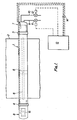
- the shower installation comprises a hollow metal support tube 1 usually of stainless steel that extends across the width of the dryer screen 2 and is carried on brackets 3, 4 each adjacent one side of the screen but outside the width of the latter.
- a nozzle carrier 5 Located within the support tube 1 is a nozzle carrier 5 carrying an air and a water nozzle in side-by-side relationship.
- the unit 5 is supported inside the tube 1 for movement along the length thereof in a manner to be described in more detail below.
- the tube 1 has a longitudinal slot 6 in its underneath surface (as seen in Fig. 1) through which exit air and water from the nozzles.
- bracket 3 Adjacent the bracket 3 is an end cap 7 also of stainless steel and detachably secured to the tube 1 while a similar cap 8 is detachably secured to the other end of the tube 1 adjacent the bracket 4.
- Air and water are supplied to the air and water nozzles via supply. lines 9 and 10 respectively, control over the-flow being exercised by respective valves 11 and 12, operation of which is controlled from a remote control panel 13. Extending from the panel 13 are control lines 14 over which are sent control signals for operating a drive motor 15 housed in end housing 8 and signals indicating the movement of the unit 5.
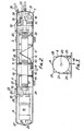
- Fig. 2 shows the tube 1 on a larger scale and it will be seen that there is a driving member 16 mounted coaxially within the tube. Extending from each end of the drive member 15 are stub axles 17, 18 rotatably mounted in bearings 19, 20 carried by bearing housings 21, 22 mounted internally in the tube 1 at the ends thereof.
- axle 17 is fitted with an internal driving key 23 by means of which the axle is drivingly coupled to the output shaft 24 of driving motor 15 mounted cantilever fashion on an end plate 25 releasably secured to the end face of bearing housing 21.
- End cap 8 is held in position at the end of the tube 1 by means of four, equi-spaced releasable, over-centre buckle-type clamps, one, 26, of which is seen in Fig. 2..
- the domed end 27 of end cap 8 is apertured centrally as at 28 to provide an optional cable entry which when not in use is closed by a plug 29 as shown.
- the other end cap 7 is also secured to the adjacent end of tube 1 by means of four releasable clamps and one of these is indicated at 3D.
- the domed end wall 31 of end cap 7 is apertured to accept two end fittings joined inside the end cap to the ends of two coiled flexible tubular supply lines SL.
- Fig. 2 only one of the end fittings is seen at 32, the second fitting being immediately beneath fitting 32.
- the end fittings are coupled to quick release connectors which join the fittings to the respective air and water supply lines 9 and 10.
- One. of the quick release connectors is indicated by reference 33.
- the domed end 31 is also apertured to receive another end fitting 34 that joins a tube 35 via a quick release coupling 36 to a source of cooling air (not shown).
- the tube 35 extends longitudinally along inside tube 1 being protected by a hollow cylindrical guide 37 supported between the bearing housings 21.
- the tube 35 terminates at a point within end cap 8 just beyond bearing housing 21. Also passing through the domed end wall 31 and along guide 36 are the power supply and control cables for motor 15.
- Part of the driving member 16 is shown on an enlarged scale in Fig. 4. ' It comprises a helical strip 38 supported on longitudinally extending sup - ports 39.
- both the strip 38 and the supports 39 are of a suitable grade-of stainless steel and the strip is welded to the supports to give a pitch of 8 turns per 5 cm of length.
- the construction provides a light but very strong support and drive.member.
- the nozzle carrier 5 is of generally cylindrical form and is made from a plastics material e.g. PTFE. It has a bore screws-threaded to match the pitch of the helical strip 38.
- the external surface of the cylinder is contoured to provide a flat mounting surface for a nozzle unit 40 carrying a water jet (not shown) and an air nozzle 41. As can be seen from Fig. 2, the nozzle 41 extends through the slot 6.
- the unit 40 is mounted on the carrier 5 in such manner that the air nozzle can be withdrawn inside the tube 1 for . assembly purposes and in circumstances to be described in detail below.
- the external surface of the carrier 5 has a longitudinal slot to accommodate the guide 37.
- the water nozzle is located within the tube 1 and is protected'thereby but is positioned so as to be able to discharge a jet of water through the slot 6.
- the coiled flexible supply lines -referred to above are nested round the driving member 16 as can be seen from Fig. 2 and extend along the driving member to the carrier 5 where the air supply line is connected to the air nozzle 41 and the water supply line is joined to the water nozzle.
- cleaning brushes 42, 43 each comprising radially arranged bristles whose inner ends rub along the surface of the driving member 16 and whose outer ends rub along the inside surface of the tube 1.
- the bristles are attached to annular carriers 44, 45 that are secured to the end faces of the nozzle carrier as shown in Fig. 2.
- the control gear associated with the control panel enables a user to select one of a number of operating modes.
- the nozzle carrier 5 may be required to traverse across the entire width of the dryer screen 2 (Fig. 1) either once or for a specified period or continuously until stopped.
- the user may require the nozzle carrier to move to and fro across a part only of the screen and this can be achieved by the user first setting the carrier centrally of the required part and then the amplitude of movement required to traverse the-carrier along the length of the part.
- Controls are also provided to enable a user to select for use either the air nozzle only or the water nozzle only or both.
- the shower works under arduous conditions including exposure to steam and a hot atmosphere.
- an external .source of cooling air is used to keep the motor cool. Cooling air from the source is fed along tube 35 to the end cap 8 where it is circulated over and through the motor 15 by a circulating fan associated with the motor.
- the cleaning brushes 42, 43 rub along the surfaces' of the member 16 and the inner surface of the tube 1 and' remove therefrom any matter that has been deposited thereon. Such removed matter normally falls through the slot 6.
- the form of the driving member 16 provides a substantially rigid support and drive for the nozzle carrier and is of light weight.
- the driving member is supported at its ends only and does not require any intermediate support.
- the support and driving member may be incorporated in other equipment than a shower unit.
Landscapes
- Nozzles (AREA)
- Drying Of Solid Materials (AREA)
- Spray Control Apparatus (AREA)
- Paper (AREA)
Applications Claiming Priority (2)
| Application Number | Priority Date | Filing Date | Title |
|---|---|---|---|
| GB8228289 | 1982-10-04 | ||
| GB08228289A GB2128288B (en) | 1982-10-04 | 1982-10-04 | Improvements in or relating to support and drive members |
Publications (3)
| Publication Number | Publication Date |
|---|---|
| EP0106599A2 true EP0106599A2 (de) | 1984-04-25 |
| EP0106599A3 EP0106599A3 (en) | 1985-09-18 |
| EP0106599B1 EP0106599B1 (de) | 1988-08-10 |
Family
ID=10533365
Family Applications (1)
| Application Number | Title | Priority Date | Filing Date |
|---|---|---|---|
| EP83305867A Expired EP0106599B1 (de) | 1982-10-04 | 1983-09-29 | Unterstützungs- und Antriebsvorrichtungen |
Country Status (6)
| Country | Link |
|---|---|
| US (1) | US4674684A (de) |
| EP (1) | EP0106599B1 (de) |
| CA (1) | CA1226884A (de) |
| DE (1) | DE3377659D1 (de) |
| FI (1) | FI80490C (de) |
| GB (1) | GB2128288B (de) |
Families Citing this family (4)
| Publication number | Priority date | Publication date | Assignee | Title |
|---|---|---|---|---|
| US4598238A (en) * | 1985-04-24 | 1986-07-01 | Albany International Corp. | Electro-mechanical shower oscillator for papermaking machine |
| DE19726897C2 (de) † | 1997-06-25 | 2000-01-13 | Voith Sulzer Papiermasch Gmbh | Verfahren zum Reinigen eines Transportbandes |
| MX2021007863A (es) | 2016-02-23 | 2022-12-16 | Deka Products Lp | Sistema de control de dispositivo de movilidad. |
| US10926756B2 (en) | 2016-02-23 | 2021-02-23 | Deka Products Limited Partnership | Mobility device |
Family Cites Families (11)
| Publication number | Priority date | Publication date | Assignee | Title |
|---|---|---|---|---|
| CA864991A (en) * | 1971-03-02 | Weinbrenner Erwin | Process and apparatus for applying foam-forming mixtures | |
| US1888575A (en) * | 1928-07-06 | 1932-11-22 | Gilbert J Scofield | Cleansing apparatus |
| GB631558A (en) * | 1945-06-22 | 1949-11-04 | Gilbert John Schofield | Improvements in and relating to reciprocating cleaning mechanisms for the felts and wires of a fourdrinier machine and for like purposes |
| US2971699A (en) * | 1957-02-27 | 1961-02-14 | Reiss Engineering Company Ltd | Liquid spray arrangements |
| US3169706A (en) * | 1963-07-02 | 1965-02-16 | Reiss Engineering Company Ltd | Reciprocating means for liquid spray arrangements |
| US3534626A (en) * | 1965-11-29 | 1970-10-20 | William I Elliott | Method and construction for cooperatively threaded parts |
| JPS49445B1 (de) * | 1968-12-27 | 1974-01-08 | ||
| US3808980A (en) * | 1972-07-03 | 1974-05-07 | C Winiarski | Conveyor mechanism for wheeled vehicle |
| US3880357A (en) * | 1974-05-23 | 1975-04-29 | Stephen J Baisch | Oscillating shower head |
| US4226129A (en) * | 1978-04-12 | 1980-10-07 | Harvey Henderson | Worm drive mechanism |
| GB2030893B (en) * | 1978-09-21 | 1982-09-08 | Albany Engineered Systems Ltd | Shower fittings |
-
1982
- 1982-10-04 GB GB08228289A patent/GB2128288B/en not_active Expired
-
1983
- 1983-09-29 DE DE8383305867T patent/DE3377659D1/de not_active Expired
- 1983-09-29 EP EP83305867A patent/EP0106599B1/de not_active Expired
- 1983-09-30 CA CA000438081A patent/CA1226884A/en not_active Expired
- 1983-10-03 FI FI833572A patent/FI80490C/fi not_active IP Right Cessation
-
1986
- 1986-05-15 US US06/865,574 patent/US4674684A/en not_active Expired - Fee Related
Also Published As
| Publication number | Publication date |
|---|---|
| FI80490C (fi) | 1990-06-11 |
| US4674684A (en) | 1987-06-23 |
| FI80490B (fi) | 1990-02-28 |
| FI833572A0 (fi) | 1983-10-03 |
| GB2128288A (en) | 1984-04-26 |
| EP0106599A3 (en) | 1985-09-18 |
| GB2128288B (en) | 1985-11-13 |
| CA1226884A (en) | 1987-09-15 |
| FI833572L (fi) | 1984-04-05 |
| DE3377659D1 (en) | 1988-09-15 |
| EP0106599B1 (de) | 1988-08-10 |
Similar Documents
| Publication | Publication Date | Title |
|---|---|---|
| US4734950A (en) | Cleaning apparatus for exterior of elongated members | |
| US5572957A (en) | Automated sludge lance | |
| CA1162462A (en) | Filter cleaning system | |
| US4690159A (en) | Rotary cleaning device | |
| US5065703A (en) | Flexible lance for steam generator secondary side sludge removal | |
| KR970008137B1 (ko) | 슬러지 침적물 제거용 가요성 렌스 및 그의 구동 시스템 | |
| EP0007557B1 (de) | Dekontaminierungsvorrichtung zur Dekontaminierung der Deckelkammern von nuklearen Dampferzeugern | |
| EP0432889B1 (de) | Schlammlanze | |
| EP0526120A1 (de) | Gleitende Lanzeführung und flexible Lanze | |
| US4603661A (en) | Hydroblast cyclone cleaner apparatus and method | |
| US4445465A (en) | Sludge lance advancing apparatus | |
| EP0755495A1 (de) | Reinigungssystem für den oberen rohrbündel eines dampferzeugers sowie verfahren | |
| EP0106599A2 (de) | Unterstützungs- und Antriebsvorrichtungen | |
| US4971140A (en) | Process and equipment for the maintenance of the secondary section of a heat exchanger | |
| CA1140529A (en) | Decontamination apparatus | |
| EP0424487B1 (de) | Apparat zum bewegen eines flexiblen kabels durch ein zu reinigendes rohr | |
| US5813370A (en) | Steam generator lancing system | |
| GB2031101A (en) | Oscillating soot blower | |
| EP0027388B1 (de) | Verfahren und Apparat zur Dekontamination | |
| KR20020032131A (ko) | 증기발생기 슬러지 세정 장비 | |
| CA2262335C (en) | Segmented lance assembly | |
| US4534932A (en) | Apparatus for removing cladding material from bottom portion of control rod guide tube of nuclear reactor | |
| KR100563936B1 (ko) | 고압수 분사방식의 증기발생기 슬러지 세정장비 | |
| US6105539A (en) | Steam generator top of tube bundle deposit removal apparatus | |
| GB2247163A (en) | Paint roller cleaning apparatus |
Legal Events
| Date | Code | Title | Description |
|---|---|---|---|
| PUAI | Public reference made under article 153(3) epc to a published international application that has entered the european phase |
Free format text: ORIGINAL CODE: 0009012 |
|
| AK | Designated contracting states |
Designated state(s): DE FR IT SE |
|
| PUAL | Search report despatched |
Free format text: ORIGINAL CODE: 0009013 |
|
| AK | Designated contracting states |
Designated state(s): DE FR IT SE |
|
| 17P | Request for examination filed |
Effective date: 19851108 |
|
| 17Q | First examination report despatched |
Effective date: 19870126 |
|
| ITF | It: translation for a ep patent filed | ||
| GRAA | (expected) grant |
Free format text: ORIGINAL CODE: 0009210 |
|
| AK | Designated contracting states |
Kind code of ref document: B1 Designated state(s): DE FR IT SE |
|
| REF | Corresponds to: |
Ref document number: 3377659 Country of ref document: DE Date of ref document: 19880915 |
|
| ET | Fr: translation filed | ||
| PLBE | No opposition filed within time limit |
Free format text: ORIGINAL CODE: 0009261 |
|
| STAA | Information on the status of an ep patent application or granted ep patent |
Free format text: STATUS: NO OPPOSITION FILED WITHIN TIME LIMIT |
|
| 26N | No opposition filed | ||
| ITTA | It: last paid annual fee | ||
| PGFP | Annual fee paid to national office [announced via postgrant information from national office to epo] |
Ref country code: FR Payment date: 19920818 Year of fee payment: 10 |
|
| PGFP | Annual fee paid to national office [announced via postgrant information from national office to epo] |
Ref country code: DE Payment date: 19920930 Year of fee payment: 10 |
|
| PGFP | Annual fee paid to national office [announced via postgrant information from national office to epo] |
Ref country code: SE Payment date: 19930924 Year of fee payment: 11 |
|
| PG25 | Lapsed in a contracting state [announced via postgrant information from national office to epo] |
Ref country code: FR Free format text: LAPSE BECAUSE OF NON-PAYMENT OF DUE FEES Effective date: 19940531 |
|
| PG25 | Lapsed in a contracting state [announced via postgrant information from national office to epo] |
Ref country code: DE Effective date: 19940601 |
|
| REG | Reference to a national code |
Ref country code: FR Ref legal event code: ST |
|
| PG25 | Lapsed in a contracting state [announced via postgrant information from national office to epo] |
Ref country code: SE Effective date: 19940930 |
|
| EAL | Se: european patent in force in sweden |
Ref document number: 83305867.0 |
|
| EUG | Se: european patent has lapsed |
Ref document number: 83305867.0 |